Diagnostic Procedures Orthodontic Seminar
Academic Level and Unit1
- DMD Level 2
- Unit B: Diagnostic Procedures
Seminar Curriculum
- Part 1: Dentofacial Proportions
- Part 2: Principles of Cephalometric Analysis
- Part 3: Space Analysis
- Part 4: Systematic Description of Malocclusion
Dentofacial Proportions2
Upon completion of this section, you should be able to:
- Describe ideal dentofacial proportions from the full face aspect, indicating the role of symmetry and the relationship of the width of upper to lower face characteristics.
- Describe ideal dentofacial proportions from the lateral aspect, indicating the a-p and vertical relationships of the upper, mid and lower face.
- Describe the method and objectives of facial form analysis.
- Discuss the limitations of facial form analysis.
- Carry out a facial form analysis.
Ideal Full Face Proportions and Symmetry
Vertical and Proportional Relationships3
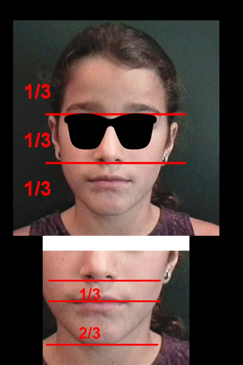
Ideal facial proportions are assessed through specific vertical and width relationships:
-
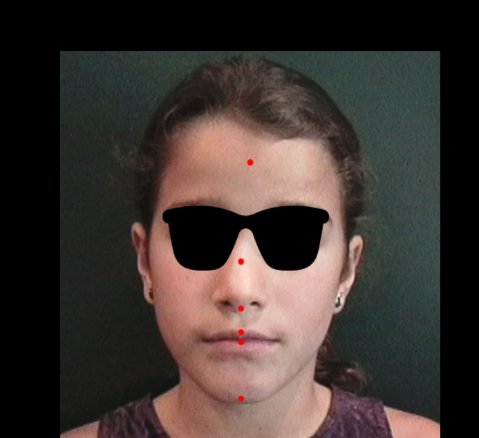
Vertical Division: The face is divided into three equal parts using two horizontal lines at the glabella and the base of the nose; harmony is achieved when these thirds are close in dimension.
-
Lower Face Height: The lower third is further divided into a 1/3 and 2/3 relationship, measured from the encounter of the lips to the chin.
-
Horizontal Division: The face is divided horizontally into fifths measured from the midline (glabella-philtrum), the inner canthus, and the outer part of the eyes to evaluate symmetry.
-
Vertical Divisions: There are three ideal vertical relationships used to define the logical face.
-
Width Characteristics: Three proportional relationships exist between the upper and lower face widths.
-
Surface Assessment: Evaluation should target the rotation, tilt, and lie of the face.
 |  |
 |  |
Anatomical Landmarks
The analysis involves examining the relationships between the following structures:
- The skull
- The orbits
- The nasal bone
- The chin (mental plane)
- The submental plane
- Glabella: Used as a reference point for vertical divisions and the vertical line for profile analysis.
- Base of the Nose: Used to define the boundary between the middle and lower thirds of the face.
- Philtrum: Used as a midline reference for horizontal fifths.
Ideal Lateral Aspect Proportions
Vertical Proportions4
The lateral aspect of the face is ideally divided into equal thirds:
- Upper third
- Middle third
- Lower third

Anteroposterior Relationships
- A-P discrepancy should not exceed 6mm.
- Natural Head Position: Photos must be oriented in the natural head position for accurate evaluation.
- Chin Position: A vertical line is traced through the glabella; a distance of 4 to 6 mm is normal, beyond which the chin is considered retrusive.
Vertical Height Variations5
- Long face height: An increase in the vertical dimension of the lower face.
- Characterized by a disproportion in midface height where the mandible typically exhibits a clockwise rotation, potentially making the chin appear deficient.
- Short face height: A decrease in the vertical dimension of the lower face
- Characterized by a deficiency in the lower third of the face.
 |  |
Facial Form Analysis Methods and Limitations67
Describe the method and objectives of facial form analysis.
Analysis Constraints8
Limitations of facial form analysis include:
- Soft tissue variation
- Ethnicity
Carry out a facial form analysis.
Principles of Cephalometric Analysis
Learning Objectives9
Upon completion of this section, you should be able to:
- Discuss the background for the development of cephalometric radiography in orthodontics.
- Identify the two major uses of cephalometric radiographs in orthodontics.
- Given a cephalometric radiograph, identify and trace landmarks necessary to properly outline and evaluate the position of:
- (a) cranial base
- (b) skeletal maxilla
- (c) maxillary dentition
- (d) skeletal mandible
- (e) mandibular dentition
- Given a cephalometric tracing, evaluate whether the incisor teeth are retrusive, positioned properly or protrusive relative to their supporting bone.
- Given a cephalometric tracing, evaluate the antero-posterior and vertical relationships of the jaws to the cranial base and to each other.
- Compare and contrast the measurement analysis and template analysis methods of evaluating cephalometric radiographs.
- Given an initial and progress or final cephalometric tracing, complete an overall superimposition and maxillary and mandibular superimpositions, producing a composite tracing.
- Given a composite cephalometric tracing, describe the changes evident in the tracing and relate them to growth or treatment.
Background and Uses of Cephalometric Radiography10
Discuss the background for the development of cephalometric radiography in orthodontics.
 |  |
 |  |
Primary Applications11
The two major uses of cephalometric radiographs in orthodontics are:
-
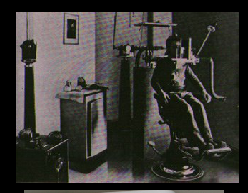
Standardization: Developed by Broadbent (US) and researchers in Germany to ensure magnification remains constant for comparison.
-
Growth Tracking: Used for follow-up to monitor patient growth before deciding on treatment timing (e.g., Class III cases).
-
Diagnosis
-
Growth and treatment effects

Landmarks and Tracing Procedures12
Given a cephalometric radiograph, identify and trace landmarks necessary to properly outline and evaluate the position of (a) cranial base, (b) skeletal maxilla, (c) maxillary dentition, (d) skeletal mandible and (e) mandibular dentition.
Sella (S) Landmark
Located in the sphenoid bone, the Sella is considered a stable point as it does not change after age 7.

Evaluation of Incisor Position13

Upper Incisor Evaluation14
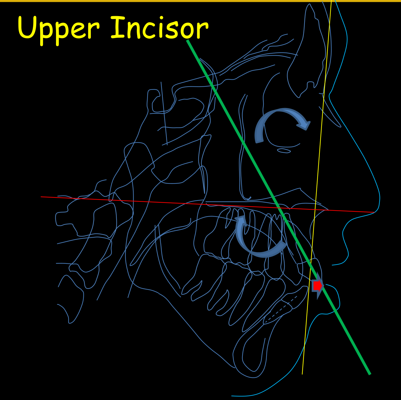
To evaluate whether the incisor teeth are retrusive, positioned properly, or protrusive relative to their supporting bone, the following measurements are used:
- 1-ANS-PNS
- 1-NA Angle: Measured as the angulation of the long axis of the upper incisor relative to the NA line.
- 1-NA Linear Distance: The horizontal distance (in millimeters) from the most projected point of the incisor to the NA line.
- 1-SN Angle: The angulation of the long axis of the upper incisor relative to the SN line.
Upper-Lower Incisor Relationship15
Evaluate whether the incisor teeth are retrusive, positioned properly, or protrusive relative to their supporting bone.
- Lower Incisors: Measured relative to the NB line and the mandibular plane.
- Proclined: Angle greater than 25 degrees.
- Protruded: Linear distance greater than 4 mm from the NB line.
- Tweed Analysis: Expects the lower incisor to be at 90 degrees to the mandibular plane.
- Interincisal Angle: The relationship between upper and lower incisors, with a normal value around 131 degrees.

Antero-Posterior and Vertical Jaw Relationships16

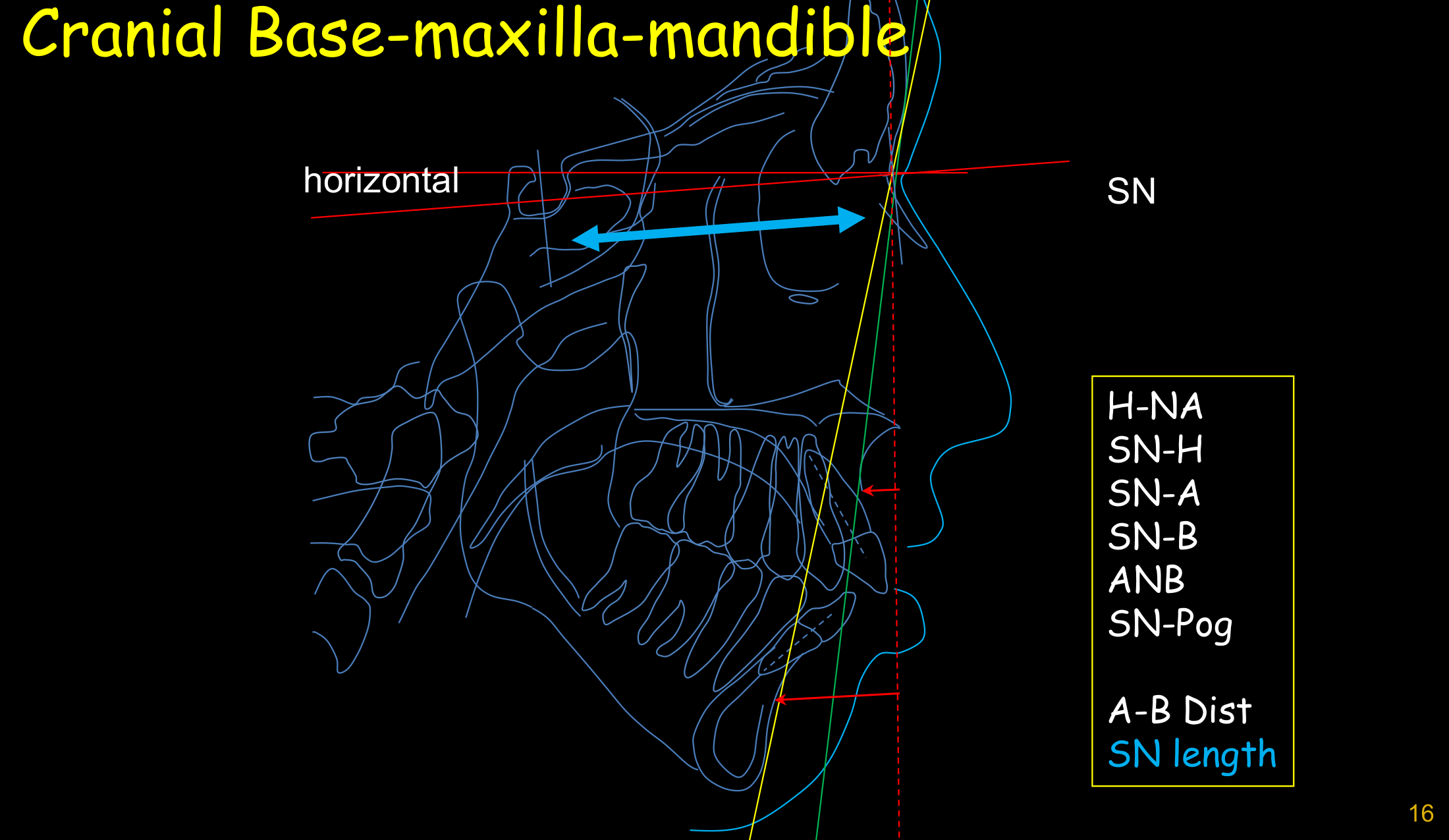
Horizontal Skeletal Relationships17
Evaluation of the antero-posterior relationships of the jaws to the cranial base and to each other using the following parameters:
- SN (Sella-Nasion)
- H-NA
- SN-H
- SN-A
- SN-B
- ANB
- SN-Pog
- A-B Dist
- SN length
Wits Appraisal18
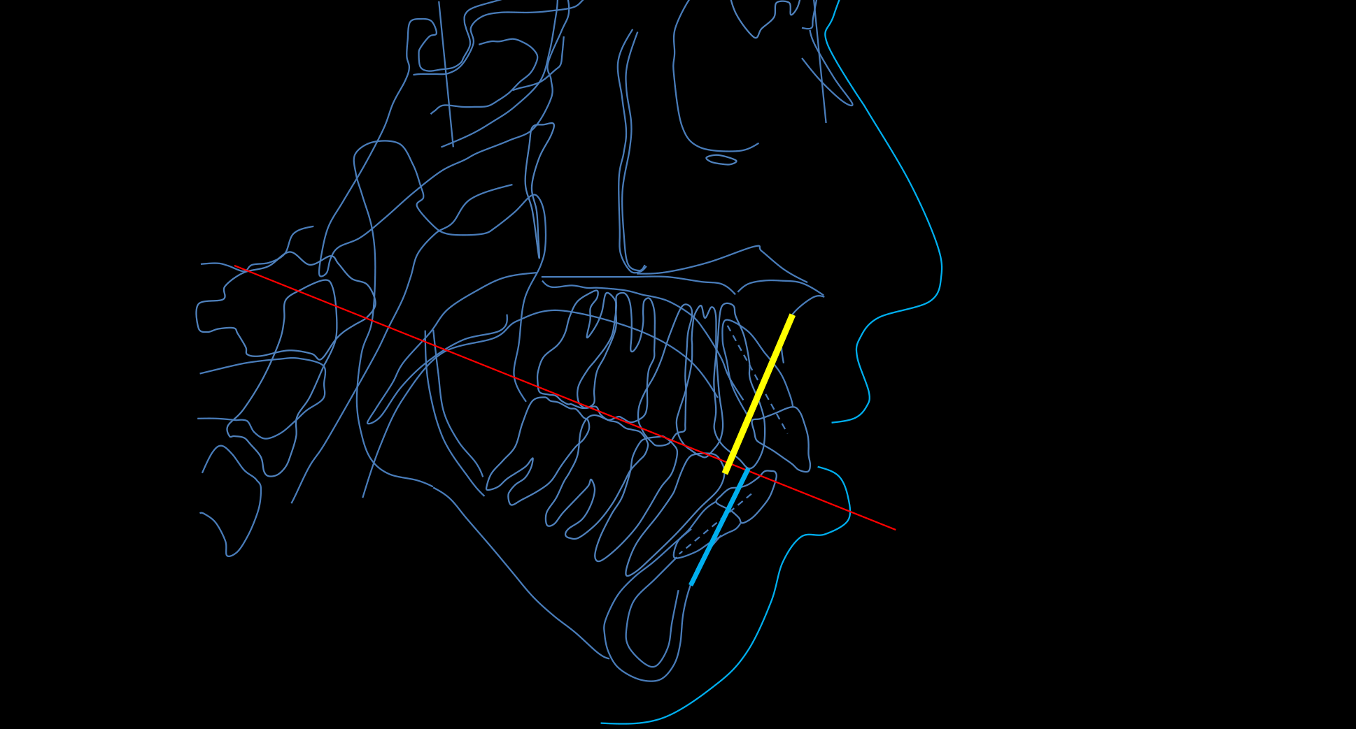
Evaluate the antero-posterior and vertical relationships of the jaws to the cranial base and to each other using the Wits analysis.
- The Wits analysis relates the jaws to the occlusal plane rather than the cranial base.
- Clinical Utility: Useful for planning orthognathic surgery by checking if the occlusal plane is steep.
- Class III Identification: If the projected point B is forward of point A, the distance is negative, indicating a skeletal Class III.
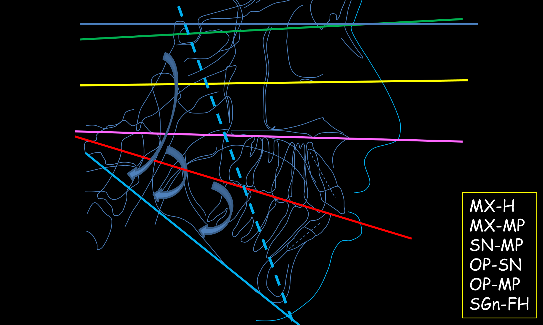
Vertical Skeletal Relationships19
| Parameter | Definition |
|---|---|
| MX-H | Gunderson’s Horizontal reference plane |
| MX-MP | Maxillary Mandle arch reference plane |
| SN-MP | Cranium to Elbow reference plane |
| OP-SN | Hyoid to Mandible reference plane |
| OP-MP | Hyoid to Ears reference plane |
| SGn-FH | Hyoid to Mandible reference plane |
Y-Axis and Vertical Growth
The Y-Axis connects the Sella (S) and Gnathion. An angle beyond 59.6 degrees relative to the Frankfort plane indicates a hyper-divergent (vertical) patient.
Facial Height and Depth20
Evaluate the vertical relationships of the jaws using the following ratios and measurements:
- LFH-TotFH
- Nart-TotFH
- NS-TotFH
- Clinical Caution: In patients with high vertical facial height, mechanics must be monitored to prevent the extrusion of molars/premolars, which could cause an open bite.

Measurement and Template Analysis Methods
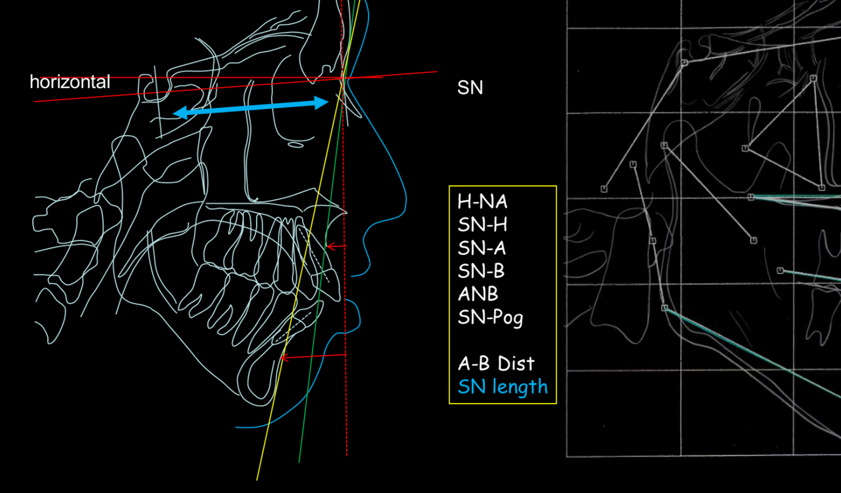
Measurement and Template Analysis Comparison21
Compare and contrast the measurement analysis and template analysis methods. Key horizontal parameters for evaluation include:
- SN
- H-NA
- SN-H
- SN-A
- SN-B
- ANB
- SN-Pog
- A-B Dist
- SN length
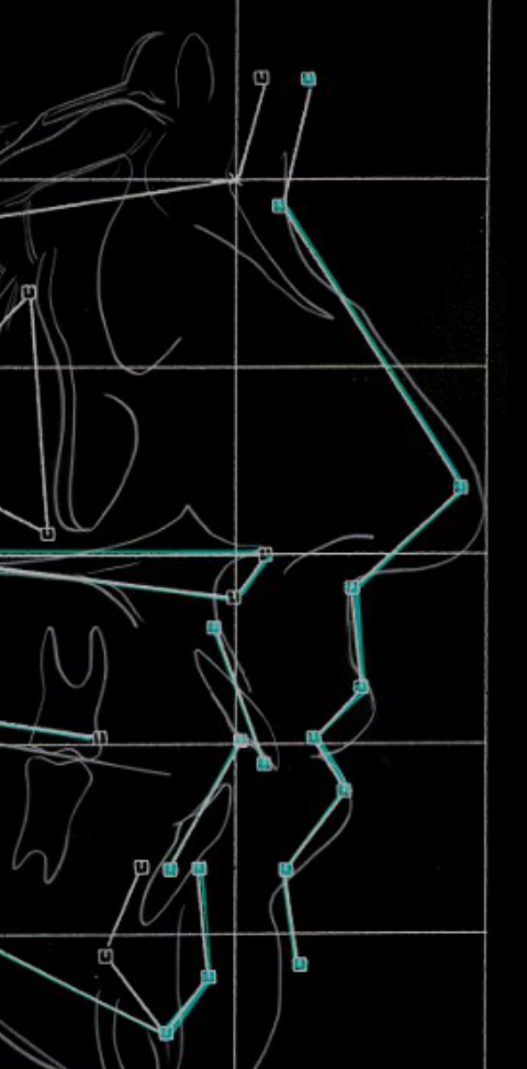
- The Mesh: A graphical representation used to compare a patient's tracing against a template based on individuals with "extraordinary" profiles to determine deviation from the ideal.
 |  |
Superimposition and Growth Evaluation
Case Study: Penny Lane22
- Initial: 3-1-53
- Final: 2-24-56
- D.O.B.: 1-7-42
Complete an overall superimposition and maxillary and mandibular superimpositions to produce a composite tracing.
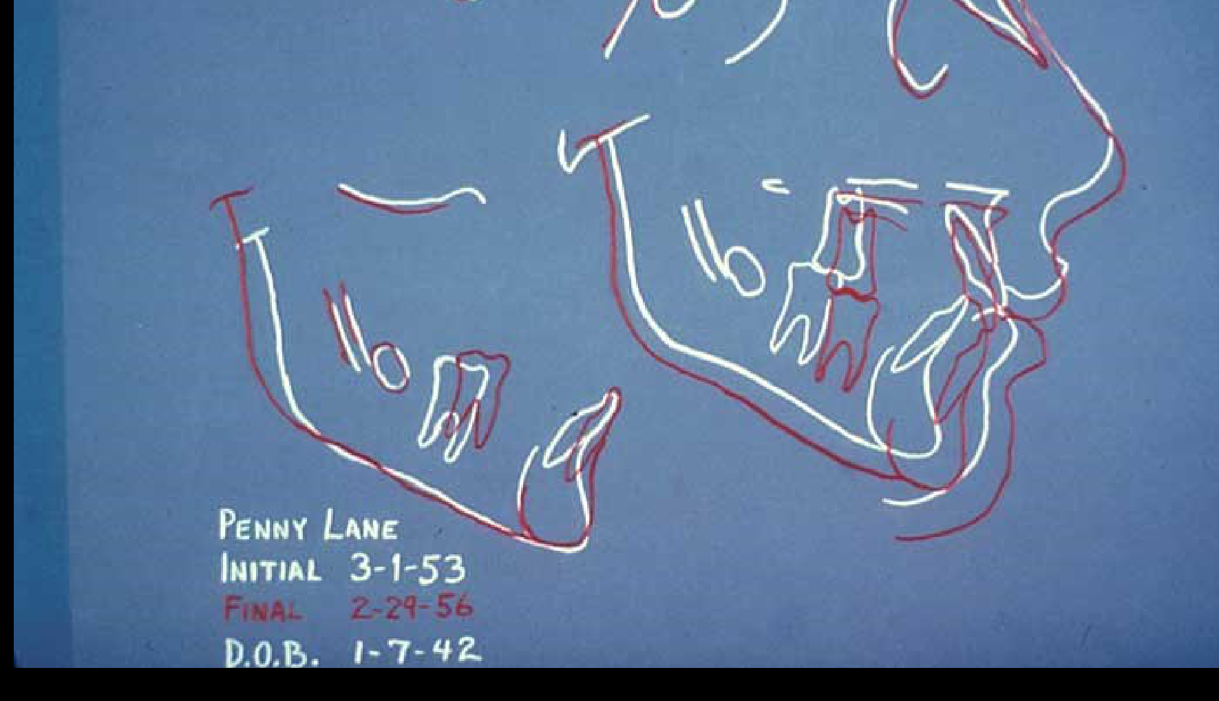
Growth and Treatment Evaluation23
Patient: Penny Lane
- Initial: 3-1-53
- Final: 2-29-56
- D.O.B.: 1-7-42
Describe the changes evident in the composite cephalometric tracing and relate them to growth or treatment.
- Cranial Base Superimposition: Uses the Sella as a stable point to compare whole tracings.
- Maxillary Superimposition: Uses the palatal plane and the key ridge.
- Mandibular Superimposition: Uses the inner part of the symphysis and the crypt of the third molars.

Space Analysis
Learning Objectives24
Upon completion of this section, you should be able to:
- Identify the four major assumptions about growth and development on which space analysis is based.
- Discuss the rationale for expecting decreased accuracy of space analysis in children who do not have a Class I jaw relationship.
- Identify the diagnostic materials needed to perform a space analysis.
- Carry out a space analysis, as described in Laboratory exercise 2.
- Indicate how you would interpret a space analysis result in a child whose facial form or cephalometric analysis indicated that the incisors were retrusive or protrusive.
Assumptions and Rationale for Space Analysis2526
- Identify the four major assumptions about growth and development on which space analysis is based.
- Lower incisors are used as a reference for prediction tables
- Prediction tables are considered valid
- Discuss the rationale for expecting decreased accuracy of space analysis in children who do not have a Class I jaw relationship.
- In Class II or Class III patients, nature often compensates, which affects predictions
- Class II: Lower incisors tend to be proclined to compensate for a deficient chin
- Class III: Lower incisors tend to be retroclined

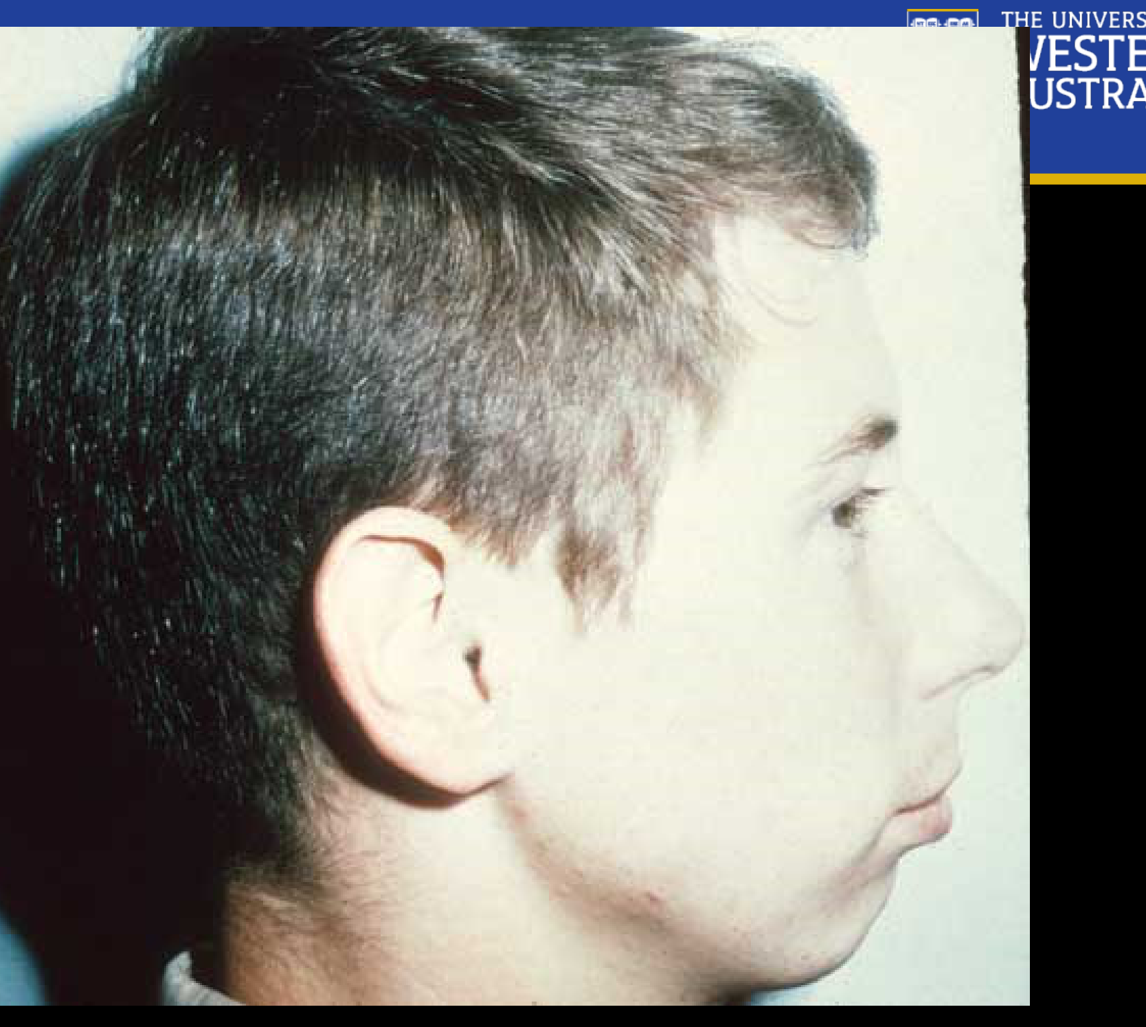
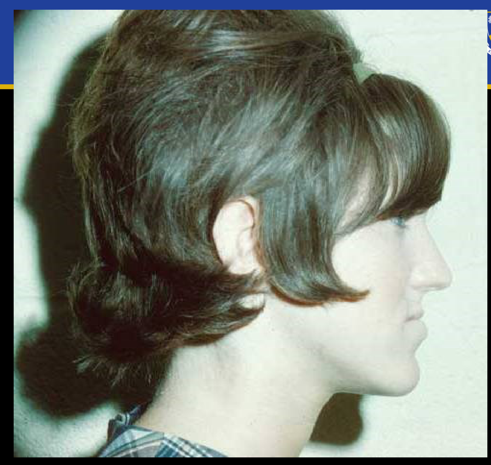
Growth and Soft Tissue Considerations272829303132
- Forward rotation
- Vertical condylar growth
- Soft tissue moulding
- Vertical Condyle Growth: Causes mandible rotation, leading to more proclined lower incisors
- Horizontal Ramus Growth: Leads to more retroclined lower incisors
 |  |  |
 |  |  |
Diagnostic Materials and Laboratory Procedures3334
- Identify the diagnostic materials needed to perform a space analysis.
- Space analysis requires specific diagnostic materials (cast models) to perform the hands-on evaluation
- Carry out a space analysis, as described in Laboratory exercise 2.
- To be done in laboratory exercise 2
 |  |
Interpretation of Space Analysis Results35
- Indicate how you would interpret a space analysis result in a child whose facial form or cephalometric analysis indicated that the incisors were retrusive or protrusive.
Systematic Description of Malocclusion
Learning Objectives36
Upon completion of this section, you should be able to:
- Identify the five major characteristics of malocclusion on which systematic description is based.
- Discuss the rationale for considering incisor crowding and incisor protrusion as being two aspects of the same thing.
- Describe how a skeletal posterior crossbite can be differentiated from a dental crossbite.
- Describe how a skeletal Class II or Class III malocclusion can be differentiated from a dental Class II or Class III.
- Describe the cephalometric characteristics of a skeletal open bite and a skeletal deep bite.
- Indicate how you would distinguish a dental anterior open bite from a skeletal open bite.
Major Characteristics of Malocclusion
Systematic Description Framework37
The systematic description of malocclusion is based on the following diagnostic considerations:
Ackermann-Proffit Classification
This method involves a systematic review of the three planes of space (Anteroposterior, Vertical, Transverse) and evaluates skeletal vs. dental problems, the dentofacial complex and soft tissues, arch symmetry, and incisor position relative to the midline and lips.
- Arch Length and Alignment: Relation to the line of occlusion.
- Dento-facial Protrusion: Assessment of the profile and incisor position.
- Transverse Relationships: Differentiation between skeletal and dental components.
- Anteroposterior (A-P) Relationships: Differentiation between skeletal and dental components.
- Vertical Relationships: Differentiation between skeletal and dental components.

Incisor Crowding and Protrusion3839
Discuss the rationale for considering incisor crowding and incisor protrusion as being two aspects of the same thing.
 |  |
Differential Diagnosis of Crossbites
Dental Crossbite Characteristics40
- Normal width of the maxilla
- Maxillary teeth leaning lingually
- Crossbite is typically caused by the lingual tipping of the upper molars while the transverse dimension of the palatal vault remains normal.

Skeletal Crossbite Characteristics
- Narrow maxilla
- Narrow palatal vault
- Maxillary teeth leaning facially
- Characterized by a very "atresic" (narrow) palatal vault.
- Compensation: Upper molars often appear vertically or buccally inclined as they attempt to compensate for the narrow skeletal base.
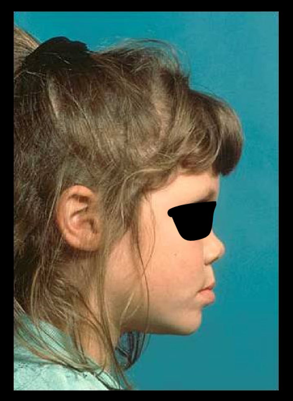
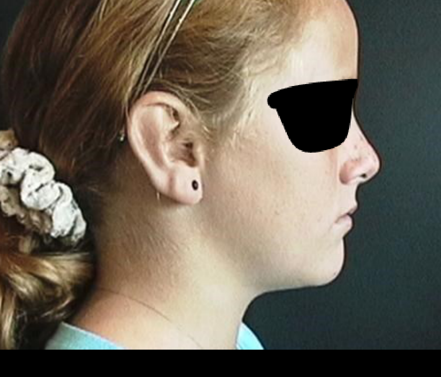
Differential Diagnosis of Class II and III Malocclusions41
Describe how a skeletal Class II or Class III malocclusion can be differentiated from a dental Class II or Class III.
 |  |
Skeletal Open Bite and Deep Bite Characteristics42
Describe the cephalometric characteristics of a skeletal open bite and a skeletal deep bite.
- Skeletal Open Bite: Associated with a longer ramus, a longer cranial base, and an obtuse goniomandibular angle.
- Skeletal Deep Bite: Associated with decreased vertical facial height and decreased vertical cephalometric planes.
 |  |
Distinguishing Dental Anterior Open Bite from Skeletal Open Bite43
To distinguish between dental and skeletal open bites, evaluate the following factors:
- Facial height
- Lip competence
- Tooth display
- Cephalometric characteristics
- Skeletal open bites usually correlate with a long facial height and increased vertical cephalometric planes.
Footnotes
-
Original PDF page 1: DMD Level II UnitB, p.1 ↩
-
Original PDF page 2: DMD Level II UnitB, p.2 ↩
-
Original PDF page 3: DMD Level II UnitB, p.3 ↩
-
Original PDF page 4: DMD Level II UnitB, p.4 ↩
-
Original PDF page 5: DMD Level II UnitB, p.5 ↩
-
Original PDF page 6: DMD Level II UnitB, p.6 ↩
-
Original PDF page 8: DMD Level II UnitB, p.8 ↩
-
Original PDF page 7: DMD Level II UnitB, p.7 ↩
-
Original PDF page 9: DMD Level II UnitB, p.9 ↩
-
Original PDF page 10: DMD Level II UnitB, p.10 ↩
-
Original PDF page 11: DMD Level II UnitB, p.11 ↩
-
Original PDF page 12: DMD Level II UnitB, p.12 ↩
-
Original PDF page 14: DMD Level II UnitB, p.14 ↩
-
Original PDF page 13: DMD Level II UnitB, p.13 ↩
-
Original PDF page 15: DMD Level II UnitB, p.15 ↩
-
Original PDF page 20: DMD Level II UnitB, p.20 ↩
-
Original PDF page 16: DMD Level II UnitB, p.16 ↩
-
Original PDF page 17: DMD Level II UnitB, p.17 ↩
-
Original PDF page 18: DMD Level II UnitB, p.18 ↩
-
Original PDF page 19: DMD Level II UnitB, p.19 ↩
-
Original PDF page 21: DMD Level II UnitB, p.21 ↩
-
Original PDF page 22: DMD Level II UnitB, p.22 ↩
-
Original PDF page 23: DMD Level II UnitB, p.23 ↩
-
Original PDF page 24: DMD Level II UnitB, p.24 ↩
-
Original PDF page 25: DMD Level II UnitB, p.25 ↩
-
Original PDF page 26: DMD Level II UnitB, p.26 ↩
-
Original PDF page 27: DMD Level II UnitB, p.27 ↩
-
Original PDF page 28: DMD Level II UnitB, p.28 ↩
-
Original PDF page 29: DMD Level II UnitB, p.29 ↩
-
Original PDF page 30: DMD Level II UnitB, p.30 ↩
-
Original PDF page 31: DMD Level II UnitB, p.31 ↩
-
Original PDF page 32: DMD Level II UnitB, p.32 ↩
-
Original PDF page 33: DMD Level II UnitB, p.33 ↩
-
Original PDF page 34: DMD Level II UnitB, p.34 ↩
-
Original PDF page 35: DMD Level II UnitB, p.35 ↩
-
Original PDF page 36: DMD Level II UnitB, p.36 ↩
-
Original PDF page 37: DMD Level II UnitB, p.37 ↩
-
Original PDF page 38: DMD Level II UnitB, p.38 ↩
-
Original PDF page 39: DMD Level II UnitB, p.39 ↩
-
Original PDF page 40: DMD Level II UnitB, p.40 ↩
-
Original PDF page 41: DMD Level II UnitB, p.41 ↩
-
Original PDF page 42: DMD Level II UnitB, p.42 ↩
-
Original PDF page 43: DMD Level II UnitB, p.43 ↩