Cephalometric Analysis: Manual Tracing of a Lateral Cephalogram
Cephalometric analysis remains a preferred tool in the diagnosis and treatment planning of orthodontic and orthognathic surgical cases. A cephalometric tracing can be prepared and analysed manually or by a computer using cephalometric tracing software. A number of software programmes on cephalometric analyses have been introduced but their widespread use has been restricted by cost factors, especially in situations having a constraint on resources. This report will give a step-by-step procedure to enable the identification of cephalometric points and planes used in orthodontic diagnosis and treatment planning and to facilitate the manual tracing of a lateral cephalogram.
Introduction to Cephalometrics1
Cephalometrics, literally “head measuring”, is the recording and interpretation of measurements of the skull made on standardized radiographs of the living head. Since the introduction of cephalometry by Broadbent and Hofrath in the 1930s, the cephalometric technique has been regarded as a most important tool for orthodontists and maxillo-facial surgeons engaged in studying dental malocclusions and the underlying skeletal discrepancies.
Applications for cephalometric analysis include:
- Case diagnosis
- Treatment planning
- Prediction of growth
- Evaluation of treatment results
Manual tracing of cephalometric films is performed by identifying radiographic landmarks on acetate overlays and using these reference points to construct lines, planes and angles to enable the measurement of linear and angular values, using a millimetre scale and a protractor. This manual process can be time-consuming and the measurements obtained may be subject to error. Whilst advances in computer science have led to the widespread application of computers in cephalometry, offering enhanced accuracy, nevertheless, the skills of manual analysis are still required.
Aim and Objectives
To enable the manual tracing of a cephalogram showing a true lateral view of the skull, and the identification of many of the cephalometric points and planes used in orthodontic diagnosis and treatment planning.
Abstract
Materials Required for Manual Tracing
- Acetate tracing paper: a sheet 210mm x 160mm
- Viewing box
- Protractor
- 300mm ruler
- Tracing template
- Adhesive tape
- Eraser
- HB lead pencil
- 4H lead pencil
- Blue, red and green coloured pencils
Step-by-Step Procedure
Step 1: Aligning the tracing paper on the lateral cephalogram radiograph
- Draw two crosses about 3 cm apart on the top left hand corner of the radiograph.
- Overlay the sheet of acetate tracing paper on the radiograph and attach the top edge with adhesive tape.
- Trace the crosses onto the tracing paper for ease of subsequent superimpositioning of the tracing.
- Write the patient’s name, age and date of radiograph above the crosses on the tracing paper.
Step 2: Identify and trace hard tissue (HT) structures and landmarks
- Trace the cranial base.
- Trace upper and lower central incisors, following the correct long axes.
- Trace upper and lower first permanent molars in relationship to each other.
- Trace the mandible and maxilla.
- Sella (S): Mid-point of sella turcica.
- Nasion (N): Midpoint of frontonasal suture.
- Porion (Po): Top of external auditory meatus.
- Orbitale (Or): Inferior border of orbit.
- Pterygomaxillary fissure (Pt): most posterior and superior point on the outline of the pterygomaxillary fissure.
- Condylion (Cd): Most superior point on the head of the condyle.
- Articulare (Ar): a point on the posterior border of the ramus at the intersection with the basilar portion of the occipital bone.
- Posterior nasal spine (PNS): Posterior point of bony hard palate.
- Anterior nasal spine (ANS): Anterior point of maxilla.
Identification of Skeletal Landmarks
Skeletal Landmark Definitions2
- A-point: Deepest point on the maxilla below ANS.
- B-point: Most posterior point on the bony curve of the mandible above pogonion.
- Pogonion (Pog): Most anterior point of bony chin.
- Gonion (Go): Most posterior and inferior point on the outline of the angle of the mandible.
- Gnathion (Gn): Most antero-inferior point on the bony chin.
- Menton (Me): Lowest point on the symphysis of the mandible.
 | 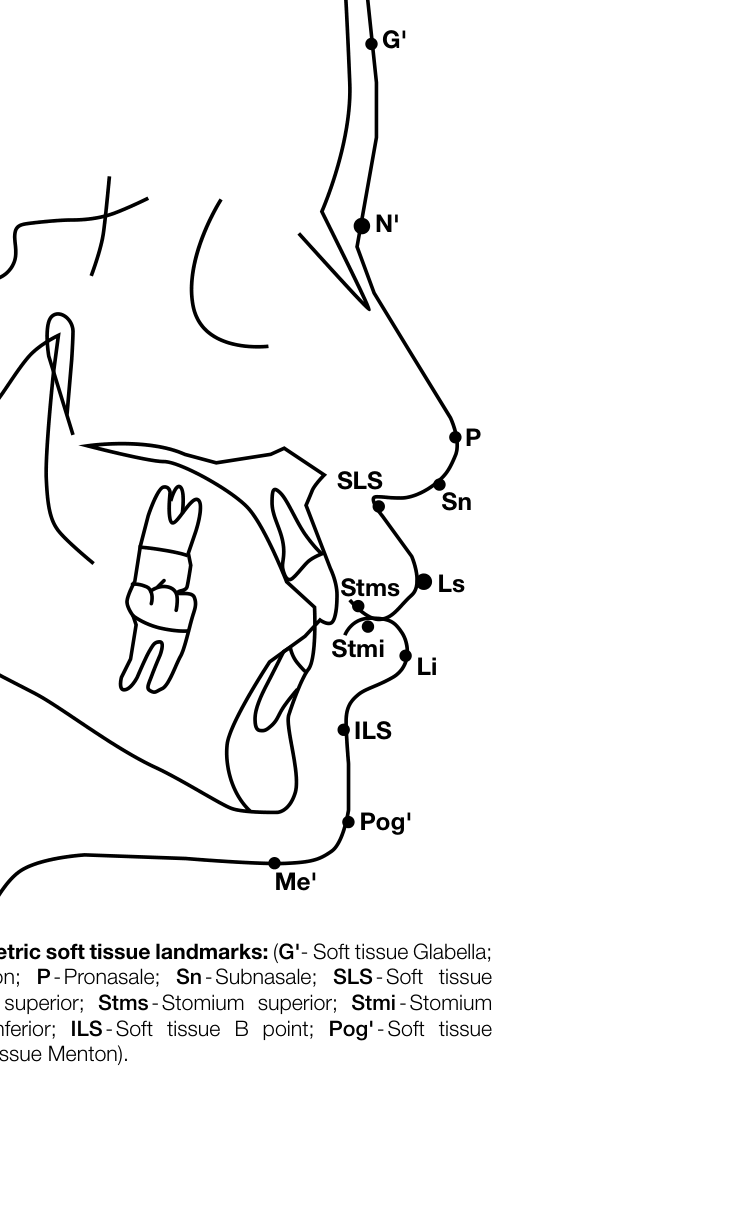 |
Identification of Soft Tissue Landmarks
Soft Tissue (ST) Outlines and Landmarks
- Trace the soft tissue outline.
- Soft tissue Glabella (G’): Most prominent point in the sagittal plane between the supraorbital ridges.
- Soft tissue Nasion (N’): Deepest part of the soft tissue outline in front of Nasion.
- Tip of Nose (P): Pronasale.
- Subnasale (Sn): Junction of nasal septum and upper lip in mid-sagittal plane.
- Soft tissue A-point (SLS): Deepest midline point on outline of the Superior labial sulcus.
- Labialis Superior (Ls): Most anterior point on outline of upper lip (vermillion border).
- Stomium Superior (Stms): Lowest midline point on outline of upper lip.
- Stomium Inferior (Stmi): Highest midline point on outline of lower lip.
- Labialis Inferior (Li): Most anterior point on outline of the lower lip (vermillion border).
- Soft tissue B-point (ILS): Deepest midline point on outline of the Inferior labial sulcus.
- Soft tissue Pogonion (Pog’): Most anterior point on outline of ST chin.
- Soft tissue Menton (Me’): Lowest point on outline of soft tissue chin.
Reference Lines and Planes
- SN line: Connects Sella and Nasion.
- Frankfurt Horizontal plane (FH): Connects Porion and Orbitale.
- Occlusal plane: Connects mesiobuccal cusp of maxillary first molar and cusp of the first premolar.
- Mandibular plane (MP): Straight line through Gnathion (Gn) and Gonion (Go).
- Y-axis: Connects Sella and Gnathion.
- NA-line: Connects Nasion and A-point.
- NB-line: Connects Nasion and B-point.
- N-Pog: Connects Nasion and Pogonion.
- APo-line: Connects A-point and Pogonion.
Angular Measurements
- Angle between SN line and FH line.
- Angle between SN line and Occlusal plane.
- Angle between SN line and Mandibular plane.
- Angle between FH line and Sella – Gnathion (Y-axis).
- Angle between SN and NA line (SNA°).
- Angle between SN line and NB line (SNB°).
- Difference between SNA and SNB (ANB°).
- Angle between FH and NPog line (Facial angle).
- Angle between long axis of U1 and NA line.
- Angle between long axis of L1 and NB line.
- Angle between long axis of U1 and L1 (Interincisal angle).
Soft Tissue Measurements and Angles
Soft Tissue Angular Relationships3
- Total facial angle (TFA) [G’-P-Pog’]: Angle formed by the intersection of the line soft tissue glabella-pronasale and the extended line soft tissue pogonion-pronasale.
- Soft tissue facial angle (FA) [G’-Sn-Pog’]: Angle formed by the intersection of lines subnasale-glabel-la and pogonion-subnasale extended (measured at the upper contained angle).
- Soft tissue facial angle (STFA) [N’-Pog’ and FH]: Angle formed by the intersection of the line soft tissue pogonion-soft tissue nasion and the Frankfort Horizontal plane (lower contained angle).
- Merrifield’s Z angle (ZA): Angle between the “profile line” (Pog’ to most protrusive lip) and the Frankfort horizontal plane.
- Nasolabial angle (NA) [Cm-Sn-Ls]: Angle between the intersection of lines tangent to the columella and upper lip.
- Pogonion-labial angle (MLA) [Li-ILS-Pog’]: Angle between the intersection of the line labialis inferius to inferior labial sulcus and a line tangent to the soft tissue pogonion, passing through labialis inferior.
- Pogonion-menton angle (PMA) [Pog’-Me’]: Angle between the intersection of lines tangent to the soft tissue pogonion and soft tissue menton.
- Holdaway angle (HA): Angle formed between the soft tissue facial plane line (soft tissue nasion-pogonion) and the H line (soft tissue pogonion to labialis inferior).
Linear Measurements (mm)
- SN length: Length of the Sella-Nasion line.
- Convexity: NB line to A-point.
- U1 to NA-line: Most anterior point of labial U1 to NA-line.
- L1 to NB-line: Most anterior point of labial L1 to NB-line.
- L1 to APog-line: APog-line to incisal edge of L1.
- Wits analysis: Distance between A and B perpendicular points on the occlusal plane.
- Upper lip length (ULL): Vertical dimension from upper stomium to ST subnasale; indicates upper incisor visibility.
- Lower lip length (LLL): Vertical dimension from lower stomium to ST pogonion; indicates lower lip curl or labio-mental fold.
- Upper lip prominence (ULP-B line): Protrusive/retrusive upper lip relative to the B Line.
- Lower lip prominence (LLP-B line): Protrusive/retrusive lower lip relative to the B Line.
- Lower lip position (LLP-H): Retruded or protruded lower lip relative to M line.
- Interlabial gap (ILG): Space between upper and lower lips when relaxed in centric relation.
- Pog-Pog’: Soft tissue thickness between hard tissue pogonion and soft tissue pogonion.
- Me-Me’: Soft tissue thickness between hard tissue menton and soft tissue menton.
Cephalometric Analysis Template4
| Category | Cephalometric Measurements | Reference Norm | Pre-Tx | Post-Tx | Interpretation |
|---|---|---|---|---|---|
| Skeletal | Facial Angle | N / < / > | |||
| Pog - NB | N / < / > | ||||
| N-Pog – A | N / < / > | ||||
| SNA | N / < / > | ||||
| SNB | N / < / > | ||||
| ANB | I / II / III | ||||
| WITS | I / II / III | ||||
| Y-Axis | N / < / > | ||||
| SN Length | N / < / > | ||||
| FH to SN | N / < / > | ||||
| PP to SN | N / < / > | ||||
| OP to SN | N / < / > | ||||
| MP to SN | N / < / > | ||||
| Gonial Angle | N / < / > | ||||
| UFH | N / < / > | ||||
| LFH | N / < / > | ||||
| Dento-alveolar | U1 to NA° | ||||
| U1 to NA mm | |||||
| L1 to NB° | |||||
| L1 to NB mm | |||||
| Inter-Incisal° | |||||
| AP° | |||||
| Soft Tissue | TFA | ||||
| FA | |||||
| STFA | |||||
| ZA | |||||
| NA | |||||
| MLA | |||||
| PMA | |||||
| UL mm | |||||
| LL mm | |||||
| ULP-B mm | |||||
| LLP-B mm | |||||
| LLP-H mm | |||||
| Inter-labial gap | |||||
| Pog-Pog’ | |||||
| Me-Me’ |
Cephalometric Diagnosis:
Legend: N-normal; ←small; >-greater; P-protrusive; R-retrusive; I-Class I; II-Class II; III-Class III; Tx-treatment

Facial Height Measurements
Anterior Facial Height Measurement5
- Measure the distance between perpendicular anterior facial height lines:
- Nasion to ANS
- ANS to Menton
Data Analysis and Documentation
- Step 7: Place your values in the table on p321 (Table 1) and analyze your findings.
Discussion
Six steps have been presented in the manual completion of a cephalometric tracing. This tracing incorporates a number of cephalometric analyses. By comparison of angular measurements with reference norm values, the clinician will interpret the results of the analysis to give a diagnosis of the presenting dento-skeletal soft tissue pattern. Comparison of the findings of the pre-treatment and post-treatment measurements will allow the clinician to assess the outcome of treatment.
Conclusion
Manual cephalometric tracing still has a role to play in orthodontic diagnosis as well as in undergraduate and postgraduate teaching and training in Orthodontics. Jackson et al. reported a high reproducibility of landmarks and measurements for both hand-tracing and digitized cephalometry. In financially constrained situations where computer cephalometric software is not affordable, manual tracing is still a useful tool. A cephalometric analysis template is proposed for easy documentation of the cephalometric measurements.
Continuing Professional Development (CPD)
Do the CPD questionnaire on page 337.
Online CPD in 6 Easy Steps:
- Go to the SADA website www.sada.co.za.
- Log into the ‘member only’ section with your unique SADA username and password.
- Select the CPD navigation tab.
- Select the questionnaire that you wish to complete.
- Enter your multiple choice answers. Please note that you have two attempts to obtain at least 70%.
- View and print your CPD certificate.
References
- Broadbent BH. A new X-ray technique and its application to orthodontia. The Angle Orthodontist 1931; 1(2):45-66.
- Hofrath ODH. Die bedeutung der röntgenfern-und abstandsaufnahme für die diagnostik der kieferanomalien. Fortschritte der Orthodontik in Theorie und Praxis 1931;1(2):232-58.
- Steiner CC. The use of cephalometrics as an aid to planning and assessing orthodontic treatment: report of a case. American Journal of Orthodontics. 1960;46(10):721-35.
- Rudolph DJ, Sinclair PM, Coggins JM. Automatic computerized radiographic identification of cephalometric landmarks. American Journal of Orthodontics and Dentofacial Orthopedics 1998;113(2):173-9.
- Downs WB. The role of cephalometrics in orthodontic case analysis and diagnosis. American Journal of Orthodontics. 1952;38(3):162-82.
- Ricketts RM. Cephalometric analysis and synthesis. The Angle Orthodontist. 1961;31(3):141-56.
- Jacobson A. The “Wits” appraisal of jaw disharmony. American Journal of Orthodontics 1975;67(2):125-38.
- Holdaway RA. A soft-tissue cephalometric analysis and its use in orthodontic treatment planning. Part I. American Journal of Orthodontics 1983;84(1):1-28.
- Arnett GW, Jelic JS, Kim J, et al. Soft tissue cephalometric analysis: diagnosis and treatment planning of dentofacial deformity. American Journal of Orthodontics and Dentofacial Orthopedics 1999;116(3):239-53.
- Bergman RT. Cephalometric soft tissue facial analysis. American Journal of Orthodontics and Dentofacial Orthopedics 1999;116(4):373-89.
- Merrifield LL. The profile line as an aid in critically evaluating facial esthetics. American Journal of Orthodontics 1966;52(11):804-22.
- Björk A. Roentgen cephalometric growth analysis. Congenital anomalies of the face and associated structures Springfield, Ill: Charles C Thomas. 1961:237-50.
- Jackson PH, Dickson GC, Birnie DJ. Digital image processing of cephalometric radiographs: a preliminary report. British Journal of Orthodontics. 1985;12(3):122-32.
Footnotes
-
Original PDF page 1: Ceph Tracing Reference, p.1 ↩
-
Original PDF page 2: Ceph Tracing Reference, p.2 ↩
-
Original PDF page 3: Ceph Tracing Reference, p.3 ↩
-
Original PDF page 4: Ceph Tracing Reference, p.4 ↩
-
Original PDF page 5: Ceph Tracing Reference, p.5 ↩