Kennedy Classification and Dental Survey Procedures
Overview of the Kennedy Classification System1
The Kennedy Classification is the most widely accepted method for categorizing partially edentulous arches. It facilitates communication between dental professionals and guides the design principles for removable partial dentures (RPDs).
- Class I: Bilateral edentulous areas located posterior to the remaining natural teeth.
- Class II: A unilateral edentulous area located posterior to the remaining natural teeth.
- Class III: A unilateral edentulous area with natural teeth remaining both anterior and posterior to it.
- Class IV: A single, but bilateral (crossing the midline), edentulous area located anterior to the remaining natural teeth.

Applegate’s Rules for Classification
To ensure consistency when applying the Kennedy system, the following rules must be observed:
- Classification should follow, rather than precede, any extractions of teeth that might alter the original classification.
- If a third molar is missing and is not to be replaced, it is not considered in the classification.
- If a third molar is present and is to be used as an abutment, it is considered in the classification.
- If a second molar is missing and is not to be replaced, it is not considered in the classification.
- The most posterior edentulous area (or areas) always determines the classification.
- Edentulous areas other than those determining the classification are referred to as modifications and are designated by their number.
- The extent of the modification is not considered, only the number of additional edentulous areas.
- There can be no modification areas in Class IV arches.
Dental Surveying Procedures
Surveying is a diagnostic procedure used to analyze the multidimensional topography of the dental arches to determine the most favorable path of insertion for a prosthesis.
- Path of Insertion: The specific direction in which a prosthesis is placed onto or removed from the abutment teeth.
- Guiding Planes: Two or more parallel vertical surfaces on abutment teeth shaped to direct the prosthesis during placement and removal.
- Retentive Areas: Regions of the teeth located gingival to the survey line (height of contour) that provide mechanical resistance to dislodgment.
- Interference: Bony prominences or tooth malpositions that obstruct the path of insertion and may require surgical or restorative correction.
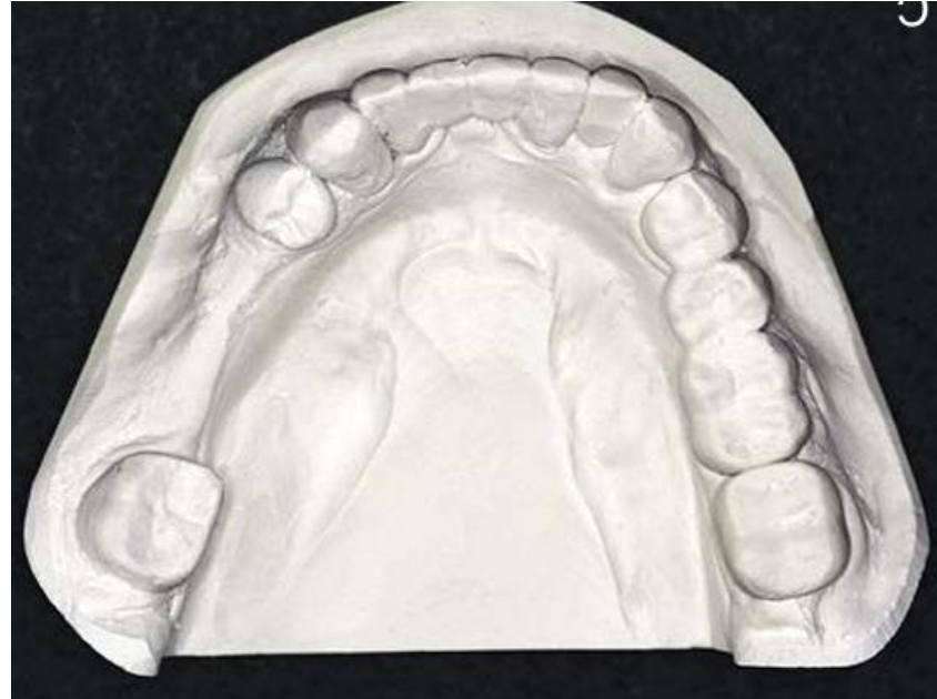
Kennedy Classification System
- Class I: Bilateral edentulous areas located posterior to all remaining teeth.
- Class II: Unilateral edentulous area located posterior to all remaining teeth.
- Class III: Unilateral edentulous area bounded by anterior and posterior natural teeth.
- Class IV: A single edentulous area, but bilateral bounded by natural teeth (crossing the midline), located anterior to remaining teeth.
Classification Categories2
 |  |
 |  |
Modification Spaces3
Each additional edentulous area (not each missing tooth) is referred to as a modification space.
Applegates Rules for Classification4
- The classification should be determined after all extractions (if applicable).
- If the third molar is missing and not to be replaced, it is not considered in the classification.
- If the third molar is present and is an abutment, it is considered in the classification.
- If the second molar is missing and is not to be replaced, it is not considered in the classification.
- The most posterior edentulous area(s) always determines the classification.
- Edentulous areas other than those determining the classification are referred to as ‘modifications’ and are designated by their number.
- The extent of the modification is not considered, only the number of additional edentulous areas.
- There is no modification in Class IV.
Dental Surveying Fundamentals
The primary objectives for surveying the diagnostic cast include:
Objectives of Surveying the Diagnostic Cast5
- To determine the most desirable path of placement.
- To identify proximal tooth surfaces that are or need to be made parallel so that they act as guiding planes.
- To locate and measure areas of the teeth that may be used for retention.
- To determine whether teeth and bony areas are areas of interference.
- To determine the most suitable path of placement that provides the best esthetic advantage.
- To permit accurate charting of the mouth preparations to be made.
- To record the cast position in relation to the selected path of placement for future reference.
Components of a Dental Surveyor
Surveying Table (Cast Holder)6
The surveying table allows the cast to be oriented at various tilts and to be fixed along one of these planes through a ball and socket joint.
 |  |
Surveying Arm7
The surveying arm is a vertical arm used to analyze the parallelism of various axial cast surfaces. The height of the arm can be adjusted, and it contains a holder so that several surveying tools may be attached and used.

Surveying Tools8
- Analyzing Rod: A thin straight metal rod used to analyze contours and undercuts in the cast. It determines relative parallelism of axial surfaces.
- Carbon Marker: A rod-like pencil lead used to mark the location of the height of contour on a dental cast.
- Undercut Gauges: Used to identify the position of desired undercuts on casts.
- Size 1: 0.25 mm / 0.01” (used for CoCr alloys)
- Size 2: 0.50 mm / 0.02” (used for Gold alloy)
- Size 3: 0.75 mm / 0.03” (used for Wrought wire)
- Surveyor Blade: Used to trim the stone tooth to adjust the height of contour to the desirable position.
The Dental Survey Process9
The dental survey process follows these sequential steps:
- Preliminary assessment of the cast
- Selecting the path of insertion (POI) of the RPD
- Initial assessment of undercuts
- Drawing the height of contour
- Survey lines of soft tissues
- Tripodization of the diagnostic cast
- Identification of retentive undercuts
- Drawing the metal framework
- Adjusting the height of contour
- Creating guiding planes
- Redraw the lines erased after changes on tooth contour
Step 1 Preliminary Assessment of the Cast10

Preliminary Assessment Tasks11
- Kennedy Classification (modifications)
- Identify the fulcrum lines (tooth number)
- Potential rest seat locations (tooth number, surface M/D/L)
- Indirect retention (tooth number, surface M/D/L)
- Find the initial POI (Perpendicular to the occlusal plane)
- Initial assessment of undercuts: verify if the POI is adequate
- Draw the height of contour on abutment teeth
- Tripodization of the diagnostic cast
- Identification of retentive undercuts (retentive clasp position)
The preliminary assessment involves:
- Classifying the edentulous arch
- Identifying fulcrum lines
- Defining potential rest seat locations

Step 2 Selecting the Path of Insertion12

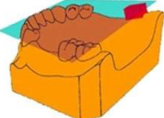
Establishing the Occlusal Plane13
The initial Path of Insertion (POI) will be perpendicular to the occlusal plane. Select three points on the model to define this plane:
- Maxilla:
- Two posterior points: mesial marginal ridge of 1st or 2nd molars in each quadrant.
- One anterior point: below the interproximal contact point between 11 and 21 (near the cingulum).
- Mandible:
- Two posterior points: mesial marginal ridge of 1st or 2nd molars in each quadrant.
- One anterior point: incisal edge of 31 or 41.
 |  |
Surveyor Alignment14
- Place the cast on the surveyor table and orient the plane of occlusion relatively horizontal.
- Using the Analyzing Rod, adjust the inclination of the Surveying Table and the vertical position of the Surveying Arm until the three points coincide with the tip of the analyzing rod without changing the vertical arm position.
1 - Preliminary assessment of the cast
2 - Selecting the path of insertion (POI) of the RPD
 |  |
 |  |
Step 3 Initial Assessment of Undercuts
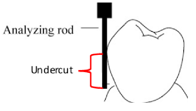
Procedure for Undercut Assessment15
- Place the analyzing rod against the axial surface of proposed abutment teeth.
- The tip of the rod should be at the level of the free gingival margin.
- If the height of contour is located in an unfavorable position (near the occlusal third or near the gingival margin) or if there is no undercut, the incline of the cast has to be changed to obtain a more favorable retention area.
- Soft tissues interferences (e.g., mandibular tori, residual ridge undercuts) also need to be avoided by modifying the path of insertion.
Step 4 Drawing the Height of Contour16
Procedure for Marking Contour17
- Place the carbon marker against the axial surface of proposed abutment teeth.
- The tip of the carbon should be placed near the level of the free gingival margin.
- Mark the height of contour around each abutment tooth.
- The position of the height of contour can be changed again by tilting the cast if necessary.
3 – Initial assessment of undercuts
4 – Drawing the height of contour

Step 5 Surveying Soft Tissue Lines18
5 - Survey lines of soft tissues
Step 6 Tripodization of the Diagnostic Cast
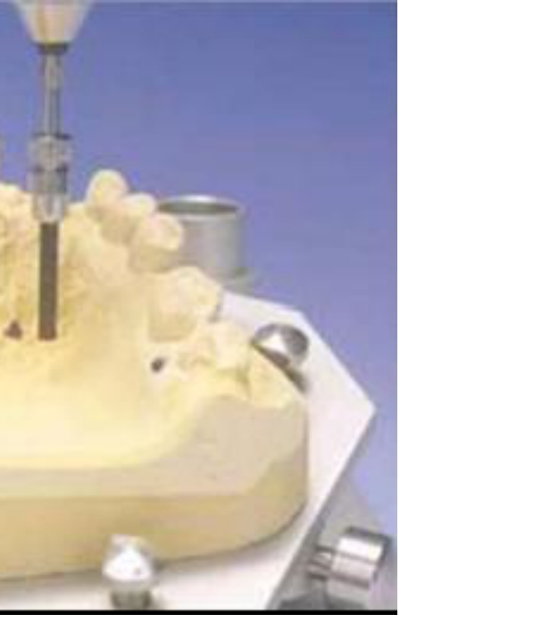
Procedure for Tripodization19
Tripodization is completed after the ideal path of insertion has been established.
- With the vertical arm of the surveyor locked, three widespread tissue points (two posterior and one anterior) are selected in relatively noncritical areas.
- Maxilla: palate
- Mandible: lingual side of alveolar ridge
- Reason: To facilitate the repositioning of the same cast or a different one in the established ideal path of insertion.
Step 7 Identification of Retentive Undercuts20
Procedure for Locating Undercuts21
- Identify where the tip of the retentive arm will be placed.
- Use a 0.25 mm gauge (0.01”).
- Bring the vertical shaft of the gauge in contact with the tooth and then move the surveying arm up or down until the terminal lip touches the tooth surface.
- Repeat the steps for all retentive arms.
6 - Tripodization of the diagnostic cast 7 - Identification of retentive undercuts
Step 8 Drawing the Metal Framework22
Rest Seats and Grids
Rest Seats
- Intercalated edentulous area: adjacent to the edentulous area.
- Free-end edentulous area: not immediately adjacent to the saddle.
- Include indirect retainers.
Grids
- Free-end saddle: 2/3 of the bearing area.
Clasp Assemblies23
Clasp assemblies consist of a retention arm and a reciprocal arm.
- Simple circumferential: rest adjacent to edentulous area.
- Reverse circumferential: rest opposing to edentulous area; requires a proximal plate.
- Ring clasp: rest on both sides of the abutment.
- Embrasure clasp: located between abutments; acts as an indirect retainer.
- T-clasp: retention arm crosses gingival margin at 90°.
- Modified T-clasp: used to avoid significant undercuts.
- I-clasp: crosses perpendicular to the gingival margin.
- RPI-clasp: consists of a rest, proximal plate, and I-bar (no reciprocal arm).
 |  |  |
 |  |  |
 |  |  |
 |
Major and Minor Connectors
Major Connector Specifications
- Mandible: 3-4 mm from the gingival margin and 5 mm of width.
- Maxilla: 5-6 mm from the gingival margin and 8 mm of width.
Types of Major Connectors
| Maxilla | Mandible |
|---|---|
| Single palatal strap | Lingual bar |
| Anterior-posterior palatal strap | Lingual plate |
| U-shaped palatal connector | Cingulum bar |
| Broad palatal strap or Palatal plate | Double lingual bar (Kennedy bar) |
| Single palatal bar | Sublingual bar |
| Anterior-posterior palatal bar |
Minor Connectors
Minor connectors join the remaining components of an RPD to the major connector.
8 - Drawing the metal framework
Step 9 Adjusting the Height of Contour
Guidelines for Contour Adjustment24
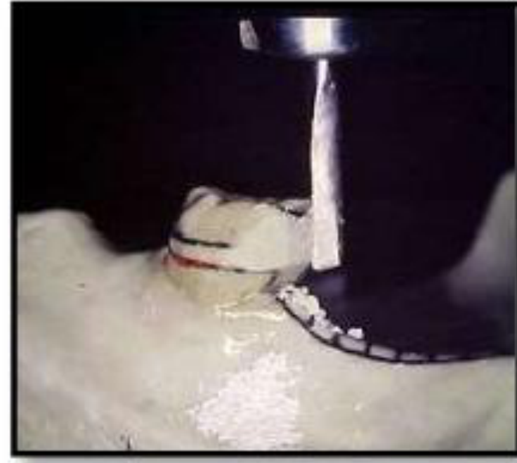
- All reciprocal arms need to be above the height of contour.
- 1/3 of the retention arm should be in the undercut.
- Use a surveyor blade to trim the plaster tooth surface.
 |  |
 |  |
Step 10 Creating Guiding Planes
Procedure for Guiding Planes25
- Use a surveyor blade to create guiding planes.
- Correct Appearance: Carbon marking shows a proper surface contact on the surveyor.
- Incorrect Appearance: Carbon marking is too thin.

Step 11 Finalizing Survey Lines2627
11 – Redraw the lines erased after changes on tooth contour
9 - Adjusting the height of contour
10 - Creating guiding planes 11 – Redraw the lines erased after changes on tooth contour

Rests and Rest Seats
Definitions and Armamentarium
Definition of a Rest28
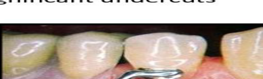
A rigid component of a removable partial denture which rests in a recessed preparation on the occlusal, lingual or incisal surface of a tooth to provide vertical support for the denture. Although a rest is a component of a direct retainer (retentive unit, clasp assembly), the rest itself is classified as a supporting element due to the nature of its function.
Rest Seat29
A portion of a tooth selected and prepared to receive an occlusal, incisal or lingual rest.
Armamentarium
- Spherical diamond bur (large diameter)
- Tapered round end bur
- Material for composite restorations
Occlusal Rest Seat Preparation
General Characteristics30
- Prepared on the occlusal surface of a bicuspid or molar.
- Preparations are entirely in enamel.
- Preparation should have a smooth flowing outline form (no sharp line angles).
 |  |
 |  |
Shape and Dimensions
- Shape: Rounded triangular shape, base facing the proximal surface at the marginal ridge, and the apex toward the center of the occlusal surface.
- Bucco-lingually: ½ inter-cusp distance (approximately one third the bucco-lingual width of the tooth).
- Mesio-distally: Equal or slightly larger than B/L size.
Structural Requirements31
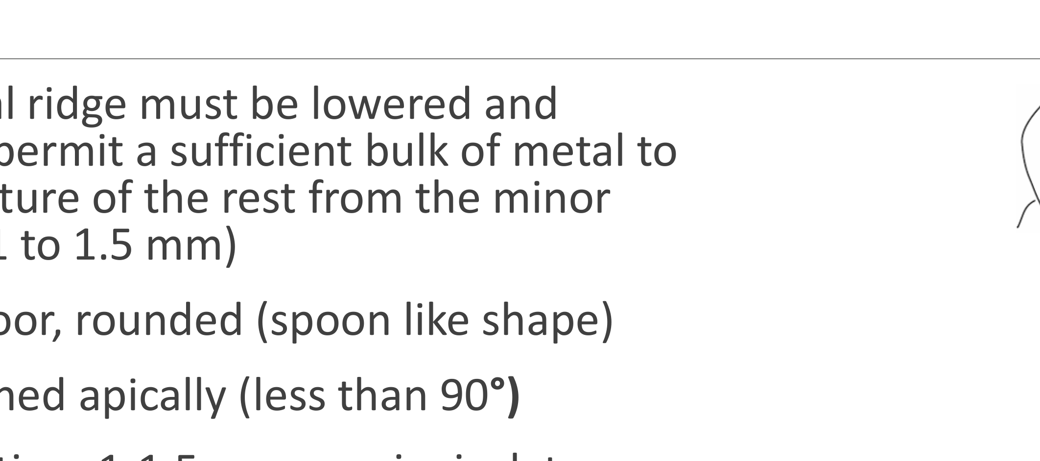
- The marginal ridge must be lowered and rounded to permit a sufficient bulk of metal to prevent fracture of the rest from the minor connector (1 to 1.5 mm).
- Concaved floor, rounded (spoon like shape).
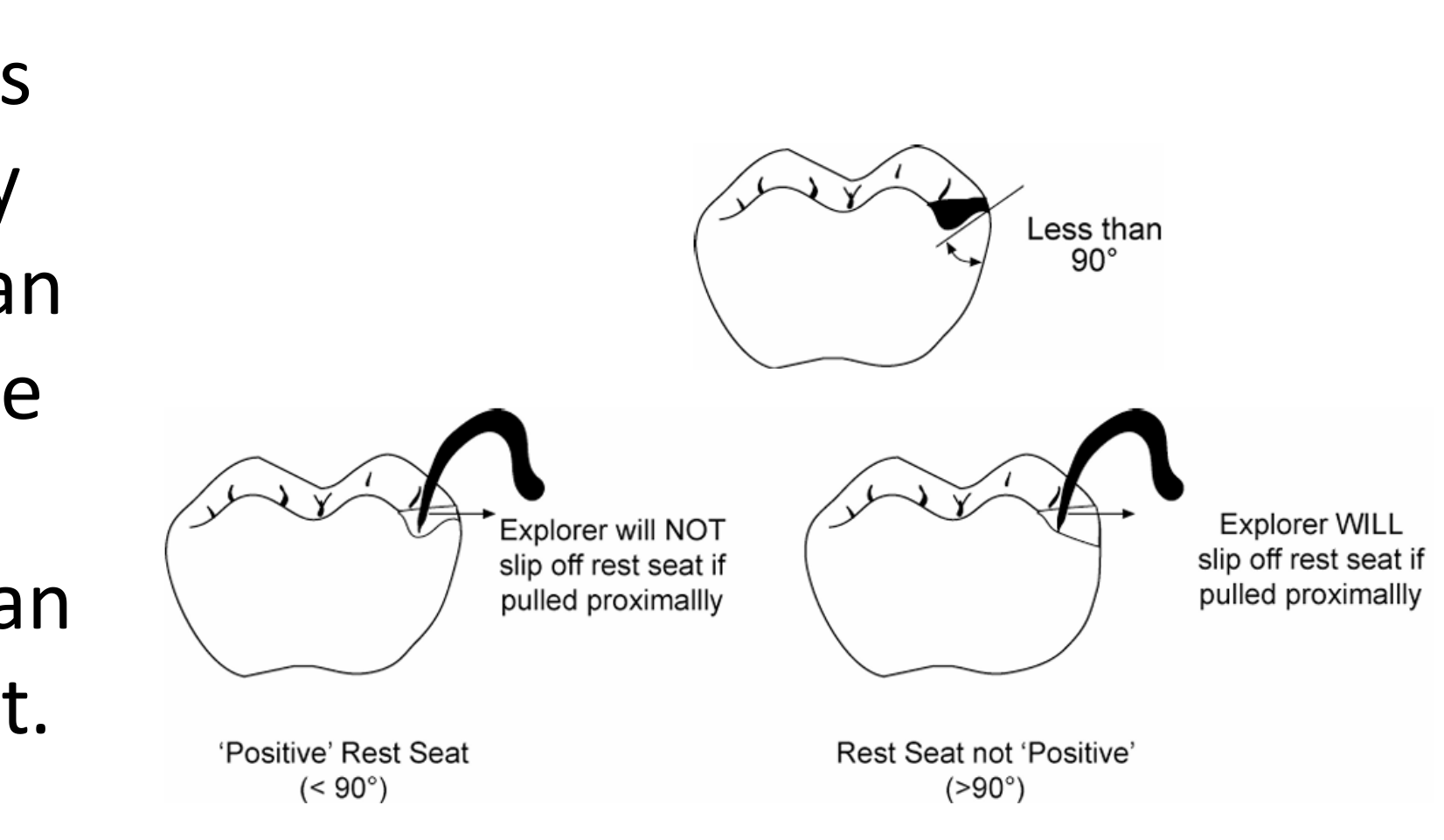
- Slightly inclined apically (less than 90°).
 |  |
Tooth Reduction
- 1-1.5mm occluso-gingival reduction at the marginal ridge.
- Taper toward the center until reaching 0.5mm reduction.
Angulation and Force Distribution32
- The floor of the rest seat should be inclined towards the centre of the tooth, so that the angle formed by the rest and the minor connector should be less than 90°. This helps to direct the occlusal forces along the long axis of the tooth.
- You can test to see if a rest seat is “positive” (less than 90°) by trying to slide an explorer tip off the rest seat.
- An angle of more than 90° fails to transmit the occlusal forces along the long axis of the tooth and permits movement of the clasp assembly away from the abutment and orthodontic movement of the tooth.
Lingual Rest Seat Preparation
Methods and Location33
- Can be done by cutting tooth structure or adding composite.
- Located on the cingulum of anterior teeth, especially the canine due to its well-developed cingulum.
Preparation Features
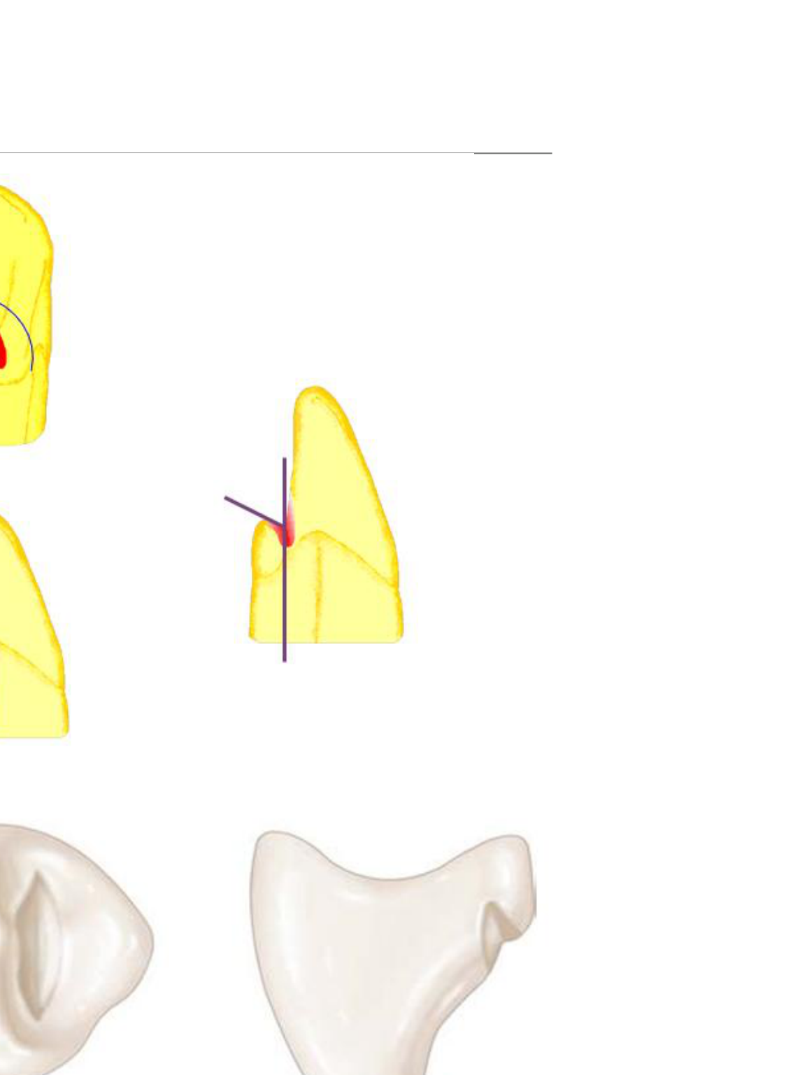
- Convex Mesio-Distally (M/D).
- Concave Bucco-Lingually (B-L): V-shaped.
- Floor angle: Less than 90°.
- Outline: Rounded, no sharp line angles.
- Minimum reduction: 0.8 mm.
Correct Preparation34
The cingulum rest seat should be prepared in the bulk of the cingulum to minimize tooth reduction. The cavosurface should be less than 90° to prevent orthodontic movements of the tooth.

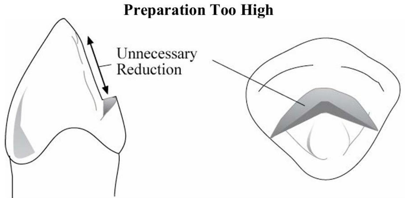
Preparation Too High35
If the preparation is started too high above the cingulum proper, much of the lingual surface of the tooth above the cingulum will need to be reduced in order to obtain sufficient width for support. On maxillary anteriors, this may also cause the rest to interfere with the opposing tooth.
Preparation Too Low36
If the preparation is started too low, much of the cingulum will need to be reduced in order to obtain sufficient width for support. Enamel is thinner in this area, and preparation could result in dentinal exposure, resulting in sensitivity. If correction of the outline form or depth is required, there will be little tooth structure remaining to make such changes.

Technical Considerations37
Care must be taken not to create an enamel undercut that would interfere with the placement of the denture. A medium or large diameter cylindrical fissure bur should be utilized approaching along the long axis of the tooth. Approach from a horizontal direction will often result in creation of an undercut incisal to the rest seat.
Force Direction in Lingual Rest Seat38
- A rest placed on an unprepared cingulum results in force being applied in a labial direction. Orthodontic movement will occur with osteoclastic activity around the centre of rotation of the root.
- A rest seat prepared in the cingulum of the tooth results in the forces being directed along the long axis of the tooth.

Composite Buildups for Cingulum Rests
Indications and Technique39
When a cingulum is poorly developed, with insufficient bulk for preparation for a cingulum rest seat, a rest seat can be made using composite resin.
- The cervical portion of the buildup should have a flat emergence profile (not over contoured) with bulk increasing toward the incisal.
- The bonded rest seat should be smooth and well polished, with no sharp line angles.
 |  |
 |
References
Primary Sources40
- Removable Partial Denture Manual, Robert W. Loney, DMD, MS, 2011
- McCracken’s Removable Partial Prosthodontics
Footnotes
-
Original PDF page 1: L12 Marwa RPD Final CSSL presentation, p.1 ↩
-
Original PDF page 2: L12 Marwa RPD Final CSSL presentation, p.2 ↩
-
Original PDF page 3: L12 Marwa RPD Final CSSL presentation, p.3 ↩
-
Original PDF page 4: L12 Marwa RPD Final CSSL presentation, p.4 ↩
-
Original PDF page 5: L12 Marwa RPD Final CSSL presentation, p.5 ↩
-
Original PDF page 6: L12 Marwa RPD Final CSSL presentation, p.6 ↩
-
Original PDF page 7: L12 Marwa RPD Final CSSL presentation, p.7 ↩
-
Original PDF page 8: L12 Marwa RPD Final CSSL presentation, p.8 ↩
-
Original PDF page 9: L12 Marwa RPD Final CSSL presentation, p.9 ↩
-
Original PDF page 11: L12 Marwa RPD Final CSSL presentation, p.11 ↩
-
Original PDF page 10: L12 Marwa RPD Final CSSL presentation, p.10 ↩
-
Original PDF page 14: L12 Marwa RPD Final CSSL presentation, p.14 ↩
-
Original PDF page 12: L12 Marwa RPD Final CSSL presentation, p.12 ↩
-
Original PDF page 13: L12 Marwa RPD Final CSSL presentation, p.13 ↩
-
Original PDF page 15: L12 Marwa RPD Final CSSL presentation, p.15 ↩
-
Original PDF page 17: L12 Marwa RPD Final CSSL presentation, p.17 ↩
-
Original PDF page 16: L12 Marwa RPD Final CSSL presentation, p.16 ↩
-
Original PDF page 18: L12 Marwa RPD Final CSSL presentation, p.18 ↩
-
Original PDF page 19: L12 Marwa RPD Final CSSL presentation, p.19 ↩
-
Original PDF page 21: L12 Marwa RPD Final CSSL presentation, p.21 ↩
-
Original PDF page 20: L12 Marwa RPD Final CSSL presentation, p.20 ↩
-
Original PDF page 26: L12 Marwa RPD Final CSSL presentation, p.26 ↩
-
Original PDF page 23: L12 Marwa RPD Final CSSL presentation, p.23 ↩
-
Original PDF page 27: L12 Marwa RPD Final CSSL presentation, p.27 ↩
-
Original PDF page 28: L12 Marwa RPD Final CSSL presentation, p.28 ↩
-
Original PDF page 29: L12 Marwa RPD Final CSSL presentation, p.29 ↩
-
Original PDF page 30: L12 Marwa RPD Final CSSL presentation, p.30 ↩
-
Original PDF page 31: L12 Marwa RPD Final CSSL presentation, p.31 ↩
-
Original PDF page 32: L12 Marwa RPD Final CSSL presentation, p.32 ↩
-
Original PDF page 33: L12 Marwa RPD Final CSSL presentation, p.33 ↩
-
Original PDF page 34: L12 Marwa RPD Final CSSL presentation, p.34 ↩
-
Original PDF page 35: L12 Marwa RPD Final CSSL presentation, p.35 ↩
-
Original PDF page 36: L12 Marwa RPD Final CSSL presentation, p.36 ↩
-
Original PDF page 37: L12 Marwa RPD Final CSSL presentation, p.37 ↩
-
Original PDF page 38: L12 Marwa RPD Final CSSL presentation, p.38 ↩
-
Original PDF page 39: L12 Marwa RPD Final CSSL presentation, p.39 ↩
-
Original PDF page 40: L12 Marwa RPD Final CSSL presentation, p.40 ↩
-
Original PDF page 41: L12 Marwa RPD Final CSSL presentation, p.41 ↩
-
Original PDF page 42: L12 Marwa RPD Final CSSL presentation, p.42 ↩
-
Original PDF page 43: L12 Marwa RPD Final CSSL presentation, p.43 ↩