L2 Components and Classifications12
Learning Outcomes345
Upon completion of this section, you should be able to:
- Identify the various components of a Removable Partial Denture (RPD).
- Discuss the concepts and clinical applications of direct and indirect retainers.
- Classify partially edentulous arches based on topography, physiology, and biomechanics.
- Visualize the application of RPD designs to specific clinical scenarios
NEVER
Unilateral Extension Design and Aspiration Risk
A critical safety concept involves the prohibition of unilateral designs. If a patient requires replacement of a single tooth, the framework cannot extend only to one side of the arch. Such a design provides sufficient support during vertical biting but lacks stability against dislodging forces. When a patient consumes sticky foods, the denture can easily lift, creating a significant risk of swallowing or aspiration, making it a life-threatening appliance.



Components of Removable Partial Dentures6789101112131415
Framework Design Principles
The foundation of a cobalt-chrome (chrome) partial denture is its metal framework, which must extend bilaterally across the dental arch for functional stability and safety.
-
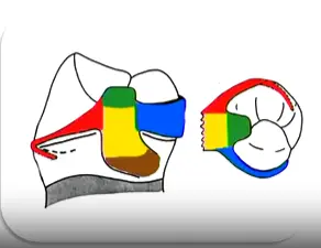
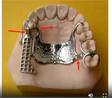
Clasp: rest, retentive and reciprocal arms, proximal plate

- Rest: A rigid component providing vertical support and preventing tissue-ward movement.
- Retentive Arm: Positioned buccally; the terminal third is flexible to engage the undercut for retention.
- Reciprocal Arm: Entirely rigid, positioned lingually above the height of contour to counteract horizontal forces.
- Proximal Plate: Contacts the proximal surface to contribute to stability and guide the path of insertion.
-
Rest (alone)

-
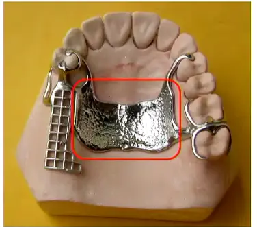
Major connector
- Primary rigid structure connecting both sides; must maintain close contact with the palate (upper) or have slight relief (lower) to transfer occlusal loads.
-
Minor connectors
- Join the clasp assembly or acrylic grid to the major connector.
- Join the clasp assembly or acrylic grid to the major connector.
-
Saddle
- Anterior Region: The buccal flange provides critical lip support.
- Free-End Saddles: Must extend to the maximum bearing area to prevent overloading the abutment tooth.
-
Artificial teeth

Ceramic Teeth Selection
Clinicians should decline requests for ceramic teeth because they do not bond well to acrylic, add excessive weight to upper dentures, and cause uncomfortable clicking sounds or excessive wear on opposing natural enamel.
Retention Concepts: Direct and Indirect Retainers
Direct Retainers
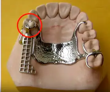
A direct retainer is any component that prevents the denture from moving away from the tissues (gingival-occlusal direction), typically engaging undercuts on abutment teeth. In a distal extension (free-end saddle) case, the clasp nearest to the edentulous space acts as the direct retainer, preventing the saddle from lifting when sticky foods are encountered.
Fulcrum Lines and Indirect Retainers
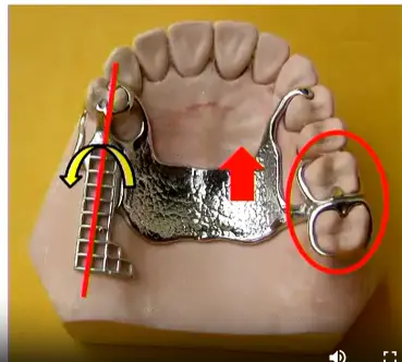
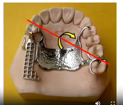
When forces act on the denture, rotation occurs around an axis called the fulcrum line (fulcrum of rotation), which passes through the most posterior retainers on each side of the arch.
- Rotation Scenario: When a patient bites on the buccal side of a free-end saddle, the denture tends to rotate around the fulcrum line, causing the opposite side to lift away from the tissue.
- Indirect Retainer Function: Components placed anterior to the fulcrum line (such as rests or clasp assemblies on the opposite side of the arch) act as indirect retainers. They prevent this rotational movement by engaging the tooth surface when the distal extension lifts. For example, when sticky food lifts a posterior saddle, the rest on an anterior abutment prevents the rotation by contacting the occlusal surface.
Clinical Application
Effective RPD design requires strategic distribution of components to counteract all potential movements:
- Direct retainers prevent vertical dislodgement
- Indirect retainers prevent rotation around the fulcrum line
- Rests prevent tissue-ward movement and can serve dual functions as indirect retainers depending on the fulcrum line position
- Direct retainer
- Indirect retainer
Classification of Partially Edentulous Arches1617
Importance of Classification
- Communication between professionals
- Didactic
- Standardization of treatment planning
- Standardized terminology allows precise discussion between clinicians (e.g., "Kennedy Class 3" implies a straightforward case, while "Class 1 Modification 3" indicates complexity)
- Visualize the difficulty of each case
Requirements for Classification
- Allow the visualization of edentulous areas
- Give information about the type of support
- Characterize where the alveolar bone will receive occlusal forces
- Universally accepted
Basis for Classification18
- Topographic
- Quantity and location of edentulous spaces
- Physiological
- How the bone will receive the masticatory load
- Biomechanics
- Position of direct retainers and the need for indirect retainers
Historical Classifications19
- Cummer (1920): Based on position and number of direct retainers and position of indirect retainers
- ==Edward Kennedy (1925)
- Bailyn (1928)
- Neurohr’s Classification (1939): Based on the support derived
- Godfrey (1951): Based on the location and size of edentulous spaces
- Beckett (1953)
- Friedman (1953): ABC classification (A: Anterior, B: Bounded posterior, C: Cantilever)
- ==Applegate-Kennedy (1954): Modification of Kennedy’s system
- Skinner (1959): Influenced by Cummer’s classification
- Swenson (1963)
the two important ones are the applegate Kennedy and Edward Kenedy
Kennedy Classification20
-
Relates the edentulous area and the remaining teeth
-
Does not take into account the number of missing teeth
-
Divided into 4 groups: Class I, Class II, Class III, and Class IV
-
Key Principle: The most posterior edentulous area always determines the classification (the "lowest" class number takes priority).
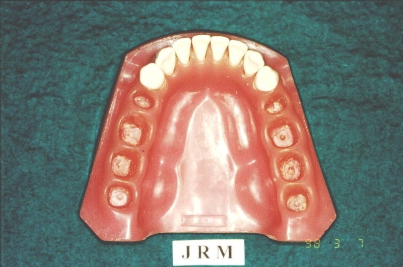
Class I21
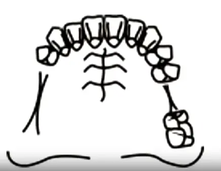
Bilateral distal edentulous areas
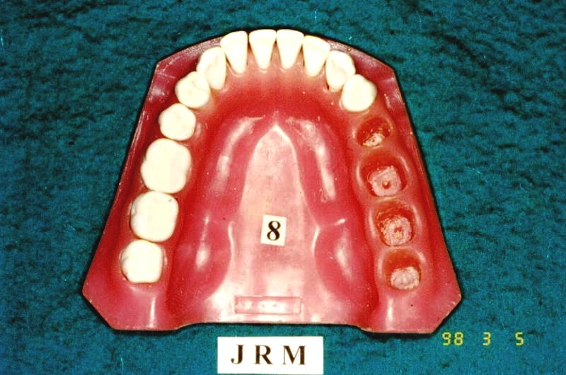
Class II22
Unilateral distal edentulous areas
Class III23
Unilateral edentulous area with teeth anterior and posterior to the edentulous area
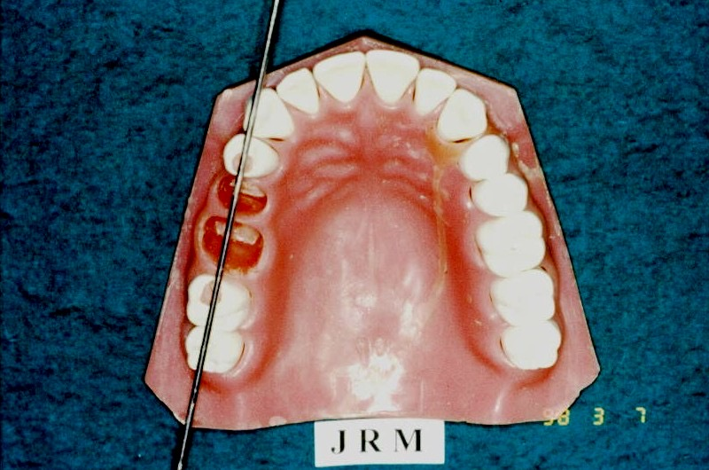
Class IV24
Anterior edentulous area crossing the midline
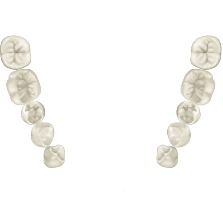
Modifications2526
- Each additional edentulous area (not each missing tooth) is referred to as a modification space.
- Include the number of modification areas in the classification.
Case Study: Classifying Multiple Edentulous Spaces
A patient presents with a free-end saddle in the posterior right quadrant, an additional bounded edentulous space in the anterior region, and another bounded edentulous space on the left side.
- The free-end saddle (most posterior) dictates the primary class: Class II
- The two additional spaces count as modifications: Modification 2
- Final Classification: Class II Modification 2.
- Class II, Modification 2
- Class II, Modification 1

Applegate’s Rules27282930
-
The classification should be determined after all extractions (if applicable).
-
If the third molar is missing and is not to be replaced, it is not considered in the classification (e.g., Class III).
-
The classification should be determined after all extractions (if applicable).
- Include teeth with Grade III mobility or furcation involvement requiring extraction. If prognosis is uncertain, classify with the tooth present and note the questionable prognosis.
-
If the third molar is missing and is not to be replaced, it is not considered in the classification.
-
If the third molar is present and is an abutment, it is considered in the classification (e.g., Class III).
-
If second molars are missing and not planned for replacement, they are not considered in the classification.
-
The most posterior edentulous area always determines the classification.
-
Edentulous areas other than those determining the classification are referred to as “modifications” and are designated by their number.
-
The extent of the modification is not considered, only the number of additional edentulous areas.
-
There is no modification in Class IV.
-
If a Class IV case had another edentulous space posterior to the anterior space, it would be reclassified as Class I, II, or III with the anterior space as the modification.
Applegate’s Modification31
Suggested two additional classifications – Classes V and VI. These are variations of Kennedy’s original Class III requiring different design considerations:
- Class V: Similar to Class III but with a large edentulous space where the anterior tooth is weak and unable to support a clasp assembly (e.g., lateral incisor).
- Class VI: Similar to Class III but with much stronger abutment teeth and a short edentulous area; this class can possibly be treated with a fixed prosthesis.

Classification According to Type of Support32
1) Tooth supported (Tooth-borne RPD)
- Load transmitted to the remaining teeth (Periodontium)
- Traction stimuli
- No occlusal load on the alveolar ridge mucosa
- These cases have the best prognosis because patients rarely complain of gingival/mucosal pain since the teeth bear all functional loads.
- All kennedy Class III are this type of RPD
Tooth and Tissue Supported3334
Category A
- Load transmitted to the remaining teeth and mucosa
- Greater transmission through the teeth
Category B
- Loading transmitted mainly to the mucosa
Case Study: Extensive Anterior Edentulous Areas
In a Class IV case missing all anterior teeth plus premolars (only molars remaining), the span is so extensive that it functions biomechanically as a free-end saddle. This should be treated as a tooth and tissue supported RPD because the anterior saddle will compress soft tissue with insufficient rigid support from distant molars.
Tissue Supported35
3) Tissue supported (Tissue borne complete denture)
- Loading transmitted to the mucosa
Biomechanics36
Movement and Force Distribution
- Possible movements of the RPD
- Presence of lever arms
Classification Types:
- INTERCALATED
- LEVERED
- COMBINED
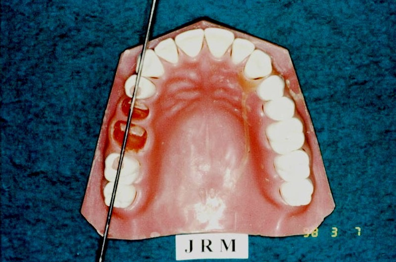
Intercalated37
- Edentulous area limited by teeth
- No free end saddles
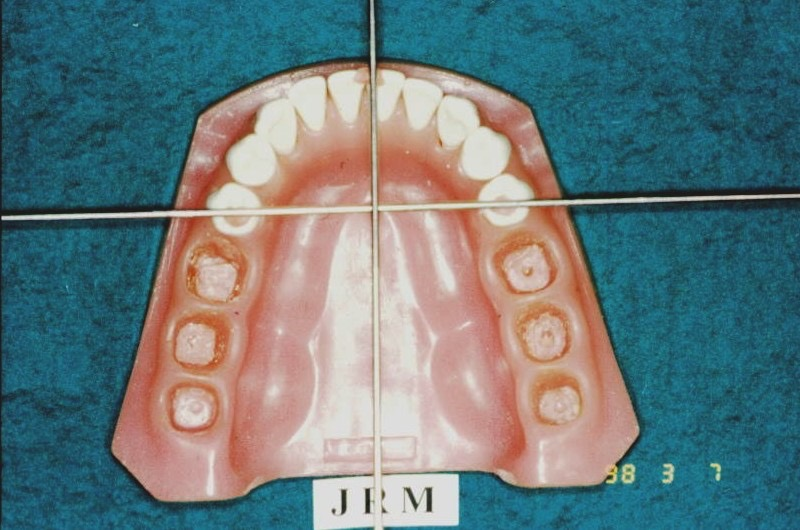
Levered38
- Free end edentulous area

Combined39
- Intercalated and free end edentulous area
- Creates complex force distributions by involving both the lever action of the free-end saddle and the intercalated nature of the bounded modification spaces.
Footnotes
-
Original PDF page 1: L2 Components and Classification, p.1 ↩
-
Original PDF page 39: L2 Components and Classification, p.39 ↩
-
Original PDF page 2: L2 Components and Classification, p.2 ↩
-
Original PDF page 3: L2 Components and Classification, p.3 ↩
-
Original PDF page 4: L2 Components and Classification, p.4 ↩
-
Original PDF page 5: L2 Components and Classification, p.5 ↩
-
Original PDF page 6: L2 Components and Classification, p.6 ↩
-
Original PDF page 7: L2 Components and Classification, p.7 ↩
-
Original PDF page 8: L2 Components and Classification, p.8 ↩
-
Original PDF page 9: L2 Components and Classification, p.9 ↩
-
Original PDF page 10: L2 Components and Classification, p.10 ↩
-
Original PDF page 11: L2 Components and Classification, p.11 ↩
-
Original PDF page 12: L2 Components and Classification, p.12 ↩
-
Original PDF page 13: L2 Components and Classification, p.13 ↩
-
Original PDF page 14: L2 Components and Classification, p.14 ↩
-
Original PDF page 15: L2 Components and Classification, p.15 ↩
-
Original PDF page 16: L2 Components and Classification, p.16 ↩
-
Original PDF page 17: L2 Components and Classification, p.17 ↩
-
Original PDF page 18: L2 Components and Classification, p.18 ↩
-
Original PDF page 19: L2 Components and Classification, p.19 ↩
-
Original PDF page 20: L2 Components and Classification, p.20 ↩
-
Original PDF page 21: L2 Components and Classification, p.21 ↩
-
Original PDF page 22: L2 Components and Classification, p.22 ↩
-
Original PDF page 23: L2 Components and Classification, p.23 ↩
-
Original PDF page 24: L2 Components and Classification, p.24 ↩
-
Original PDF page 25: L2 Components and Classification, p.25 ↩
-
Original PDF page 26: L2 Components and Classification, p.26 ↩
-
Original PDF page 27: L2 Components and Classification, p.27 ↩
-
Original PDF page 28: L2 Components and Classification, p.28 ↩
-
Original PDF page 29: L2 Components and Classification, p.29 ↩
-
Original PDF page 30: L2 Components and Classification, p.30 ↩
-
Original PDF page 31: L2 Components and Classification, p.31 ↩
-
Original PDF page 32: L2 Components and Classification, p.32 ↩
-
Original PDF page 33: L2 Components and Classification, p.33 ↩
-
Original PDF page 34: L2 Components and Classification, p.34 ↩
-
Original PDF page 35: L2 Components and Classification, p.35 ↩
-
Original PDF page 36: L2 Components and Classification, p.36 ↩
-
Original PDF page 37: L2 Components and Classification, p.37 ↩
-
Original PDF page 38: L2 Components and Classification, p.38 ↩