Elastic Materials
Learning Objectives
As you learned from your study of the biology of orthodontics, the trick in moving teeth is to use the right amount of force—and almost always the problem is to avoid using too much force. Teeth respond best to light continuous force. In an orthodontic appliance, how are things arranged so that the force is light and at least reasonably continuous?
The objective of this module is to help you answer that question, from both a theoretical and a practical clinical perspective.
In addition to going through the module, read Chapter 9, pp. 312-328 and Chapter 10, pp. 347-389 in the 5th edition of Contemporary Orthodontics (or pp. 359-377 and 395-429 in the 4th edition).
Precious Metals in Orthodontics
If you want to move a tooth, it’s necessary to use a spring that places a light but prolonged force against it—and that spring must function in the mouth, which is accurately described as a hostile environment. The better the spring, the less the force it delivers will decrease as a tooth moves. One possibility is a rubber band, and if you had orthodontic treatment yourself, you may have worn rubber bands connecting the upper and lower arches. Why did you have to change them every day? Because even the best latex materials lose their elasticity (spring quality) rapidly in the mouth.
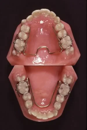
The orthodontic appliances of a century ago almost had to be made with gold that was alloyed to be as springy as possible, because nothing else would work for more than a few days in the mouth—but gold is not known for its spring qualities. An interesting appliance from that era is the Crozat appliance shown in this image, which had a gold framework and gold springs that were slightly activated every time the patient was seen. It’s interesting because it still is used occasionally, by dentists who believe that if it’s made of precious metal, it must be better. Like many other antique devices, it works by tipping teeth to a new position—but more slowly than its modern counterparts that use steel springs.
Gold wires also were used with the first fixed appliances, and the edgewise appliance that is still the basis of modern orthodontics (which we will discuss in more detail below), was engineered for use with gold wires.
Stainless Steel and Titanium
Stainless steel, which has excellent spring qualities, rapidly replaced gold when it became available for orthodontic applications. Fortunately, that transition was complete before the price of gold increased 10-fold in the 1960s. More recently, nickel-titanium and beta-titanium materials have come into wide use. It is likely that composite plastics will replace them before long. Orthodontic technology trails aerospace technology by 10-20 years. As passenger planes made largely with composite plastics (like the Boeing 787) now are replacing their aluminum and titanium predecessors, it’s a safe bet that use of composite plastics in orthodontics will follow. Like the materials in high-performance aircraft, orthodontic wires and attachments are extremely stressed, and it makes sense to use the best materials available.
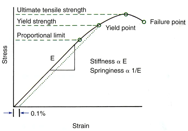
Whatever the material, however, the same physical laws apply. Different materials differ in three principal properties: strength, stiffness / springiness (which are different terms for the same property), and range. These can be illustrated by a stress / strain plot, as shown here.
On the graph, four measures of strength are shown. The proportional limit is the point at which the wire begins to deviate from elastic behavior, but it is very difficult to establish. Yield strength, the point at which a measurable deviation (like 0.1%) is observed, is taken as the point at which the elastic limit of the material is reached and it begins to bend. This value is the one typically cited in reports on strength of an orthodontic wire. The ultimate tensile strength is the point at which the material begins to fail, and the failure point is where it breaks.
The graph also shows springiness and stiffness, which are measures of the same thing, as the slope of the line. Springiness = 1 / stiffness and vice versa. The stiffer the wire, the more vertical the line will be; the springier it is, the more horizontal the line will be.
Force / Deflection Curves
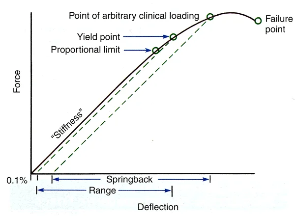
Stress and strain are internal properties of a material. In laboratory experiments, the force against a material produces a deflection, and stress and strain can be calculated from that interaction. Force / deflection curves like the one shown here are what you usually will see in reports of material properties. These curves, the original laboratory data, provide the same information as a stress / strain curve.
What properties would you want in an elastic material to be used as an orthodontic spring? Think about that from the perspective of the three key properties seen in a force / deflection plot. You’d want…
…enough strength that the spring didn’t get bent out of shape. That would mean that the distance along the y axis to the yield point should be as large as possible. Note that a spring still works beyond the yield point, but it doesn’t totally spring back to its original position if it’s loaded beyond its yield point.
…the best possible springiness. That would mean that the slope of the line should be tilted to the right (i.e., more horizontal), so that the amount of force delivered by the spring would be as constant as possible.
…the best possible range. That would mean that the distance along the x axis at the point of permanent deformation should be as large as possible.
Obviously, you can’t have the maximum of all these things. A very strong wire would tend to be stiff and to have little range, while one with maximum range would tend to be quite springy but not very strong.
Force / Deflection Curve (cont.)
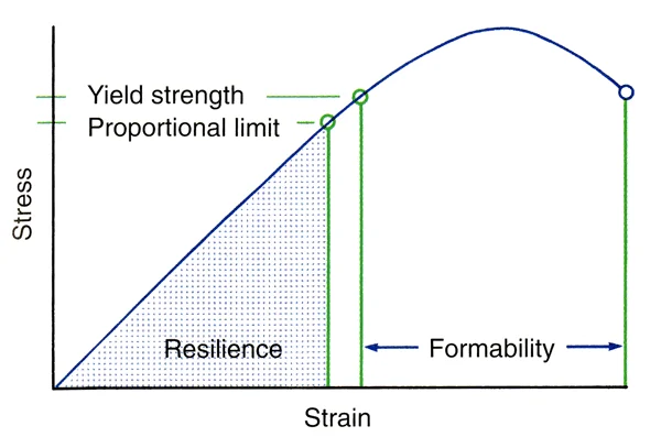
Another property that you are likely to see in descriptions of wire materials is resilience. This is the area under the curve up to the proportional limit. It gives a measure of a wire’s combination of the principal properties, and so it is likely to be used (especially in advertisements) as a way to emphasize the balance that the wire has among strength, springiness and range.
As we have noted, a spring that is deflected beyond its elastic (proportional) limit still has spring properties, it just won’t completely return to its original shape. It’s easy to bend a wire beyond its elastic limit, and when you form the wire into some shape (bend a loop in it, for instance, as you form a spring to move a tooth), you’d also like some distance between the elastic limit and the point at which the wire breaks. In fact, to bend wires you must have reasonable formability, which is the area under the curve between ultimate tensile strength and failure.
Some very springy steel wires allow almost no bending beyond their elastic limit—they break, as one student said, if you look at them cross-eyed. They’re not very useful when you’re trying to form a clasp or finger spring for a removable appliance.
Material Effects on Wire Size
The size of a wire obviously would affect its basic properties. The bigger it gets, the stronger but the less springy it will be, and the less range it will have. This means that for orthodontic purposes there are a range of useful wire sizes. You don’t have to memorize those wire sizes—you can always look them up—but you do need to understand that concept. Steel is stronger than gold or titanium, so all other things being equal, smaller steel wires would be used for orthodontic purposes.
Orthodontic springs come in two forms: cantilever beams, which are attached only at one end (image 1), and supported beams that are attached at both ends (image 2). A finger spring from a removable appliance is an excellent example of a cantilever beam, but cantilever beams also can be used with a fixed appliance. The section of an arch wire between the brackets on adjacent teeth is a supported beam.
As we have said, whatever the material (with the exception of the superelastic materials that we will discuss next), the same laws of elastic behavior apply. For any orthodontic cantilever beam, the effects of changing its size might surprise you (image 3). Doubling the size of wire used to make a finger spring:
- increases its strength 8 times: x * 2x3 = 8x strength
- decreases its springiness 16 times: x * 2x-4 = 1/16x springiness
- decreases its range by half: x * 2x = 1/2x range
Doubling the size of a supported beam produces similar but even more pronounced change—it puts a coefficient in front of the multiplier.
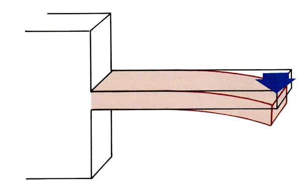 Image 1: Cantilever beam, supported on only one end. Image 1: Cantilever beam, supported on only one end. | 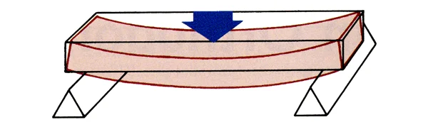 Image 2: Supported beam, free to move at abutments on each end, which is analgous to an orthodontic arch wire. Image 2: Supported beam, free to move at abutments on each end, which is analgous to an orthodontic arch wire. |
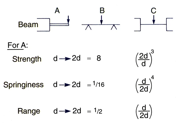 Image 3: B and C are the two types of supported beams. C is a fixed bridge, B could be an arch wire. Both are stronger, stiffer and have less range than a cantilever beam. Image 3: B and C are the two types of supported beams. C is a fixed bridge, B could be an arch wire. Both are stronger, stiffer and have less range than a cantilever beam. |
Effects of Beam Length
A second important variable in determining the principal properties of an orthodontic spring, whether it’s a cantilever or supported beam, is its length. The influence of beam length is much greater than you probably would have thought—unless you really paid attention in that pre-dental physics course or studied engineering before dental school. For a cantilever beam (finger spring), doubling its length:
- cuts its strength in half: x * 2x = ½ strength
- increases its springiness 8 times: x * 2x3 = 8x springiness
- increases its range 4 times: x * 2x2 = 4x range
It is apparent that increasing beam length produces significantly more increase in springiness and range than it costs in lower strength. For a spring, length is measured along the wire from which it is formed, not from where it is supported to where it ends up. So bending a loop or helix in the wire is a common way to gain springiness and range without reducing strength too much.
That has a very practical application. In fabricating an orthodontic spring, it would be smart to choose a relatively large wire size to gain strength, and then obtain springiness and range by making the length of wire longer between its attachment and its contact with a tooth. For that reason, it is common practice to lengthen finger springs with a helix (image 1), and to lengthen the effective distance between two teeth with brackets with loops in an arch wire (image 2).
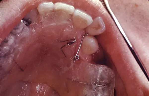 Image 1: To improve its springiness and increase its range, this spring has been lengthened by placing a loop in the wire. Image 1: To improve its springiness and increase its range, this spring has been lengthened by placing a loop in the wire. | 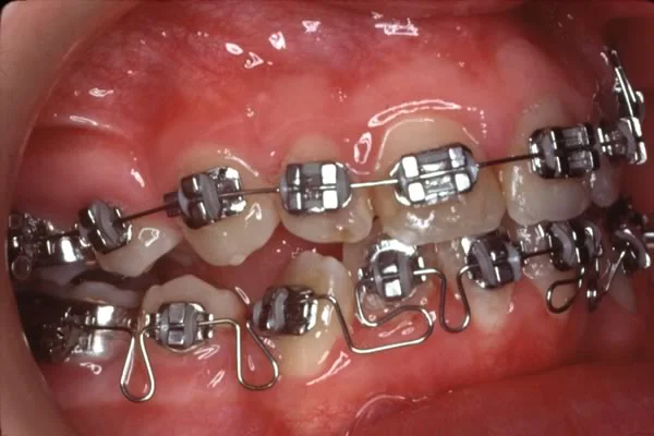 Image 2: The loops in this steel arch wire also add springiness where it is needed in the relatively stiff steel wire. Image 2: The loops in this steel arch wire also add springiness where it is needed in the relatively stiff steel wire. |
Elastic vs. Superelastic Materials
Superelasticity
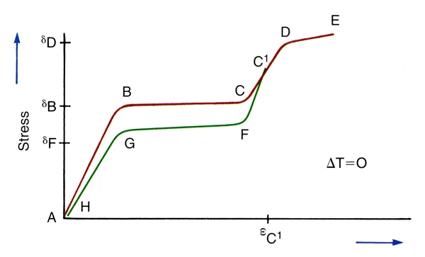
Hooke’s law, which applies to all elastic materials, is the basis for the information that we just discussed. It was almost shocking when materials that violated Hooke’s law became available for orthodontic purposes in the 1980s, not so long ago. These superelastic materials have a different force/deflection curve from elastic materials, as shown in this image. Note that there is an almost flat portion in the center of the force/ deflection curve, with an area at the beginning and end that looks like the curve for an elastic material.
You can see immediately that a superelastic spring that delivered the correct force would be quite valuable in orthodontics, because how far you deflected it would make little difference in the force it delivered over quite a wide range.
Nature of Superelasticity
How is superelasticity possible? Because superelastic materials undergo a phase transition with changes in temperature or internal stress. For a material with a transition temperature close to mouth temperature, stressing it by tying it to irregular teeth literally turns it into a different material than the one you picked up off the counter near the dental chair. The word “super” is overused, often to describe trivial things. This time the term super is warranted. You don’t often get to see physical laws apparently overturned.
For orthodontic purposes, a nickel-titanium (NiTi) alloy with a temperature transition near mouth temperature is used. It is delivered in an austenitic phase that bends elastically when it’s first deflected (distance A-B on this plot), and transitions to a martensitic phase (B-C) as internal stress builds up. That’s the upper almost flat line in a superelastic force/deflection curve. Once all the austenite has changed to martensite, there’s again an elastic curve (C-D-E).
Interestingly, the force delivered by the spring differs from the force used to deflect it initially. If you deflect the superelastic material to point C1 on the graph, the recovery curve is elastic from C1 to F, then almost flat from F to G as martensite transitions to austenite, and elastic again from G to H. It’s important to realize that the force that’s delivered to a tooth is shown by the unloading curve, the lower (green) line in the plot.
The phase transition that makes superelastic wires so useful in modern orthodontics produces an exception to Hooke’s law, but doesn’t really repeal it. Both the austenitic and martensitic phases follow the law, as this plot shows, and their properties are affected by wire size and beam length. But that superelastic plateau offers a great advantage when your goal is to align crowded and irregular teeth.
Superelastic Wires
There’s another interesting aspect of superelastic springs: the amount of force they deliver can be changed by releasing a wire from a bracket on a tooth, and then tying or clipping it back into the bracket. The unloading curve changes with different degrees of initial activation (image 1). So there’s another magic trick with a superelastic wire. You can reactivate it just by releasing it and putting it back where it was. Clinically, that’s rarely important because the plateau is nearly flat anyway, but it’s an amazing property.
Still, even with an almost magical superelastic wire, you never escape some disadvantages. The formability of a superelastic wire is almost zero. The manufacturer can shape it by controlling temperatures as it is formed, but you can’t.
It’s interesting to contrast a superelastic force/deflection curve to the curve for a stainless steel wire, elastic nickel-titanium (Nitinol) and superelastic nickel-titanium (Chinese NiTi on this graph) (image 2). The superelastic wire has far greater range and much better springiness. For elastic wires, the activation and deactivation curves have the same slope; for superelastic wires, they’re different.
How much force would you want a superelastic spring to deliver? This is shown on the plot by the deactivation (unloading) segment of the curve. You have already learned the desired force magnitude for the various types of tooth movementt in your study of the biology of tooth movement. Superelastic orthodontic wires are particularly useful in aligning crowded and irregular teeth, which usually requires tipping, rotation and extrusion (images 3, 4, 5). For all these movements, the optimal force is about 50 grams. So that’s what you’d like the superelastic wire to deliver during initial alignment.
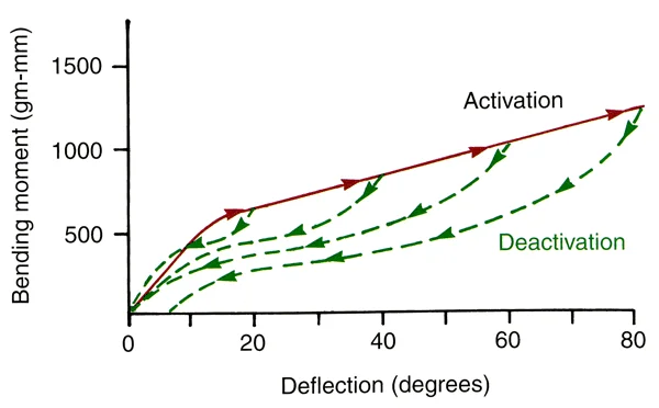 Image 1: Activation (solid line) and deactivation (dashed line) curves for a superelastic wire. Image 1: Activation (solid line) and deactivation (dashed line) curves for a superelastic wire. | 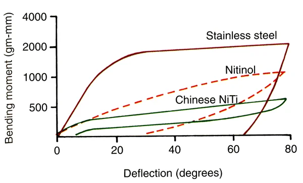 Image 2: Force-deflection curves for steel, elastic NiTi and superelastic NiTi wires Image 2: Force-deflection curves for steel, elastic NiTi and superelastic NiTi wires |
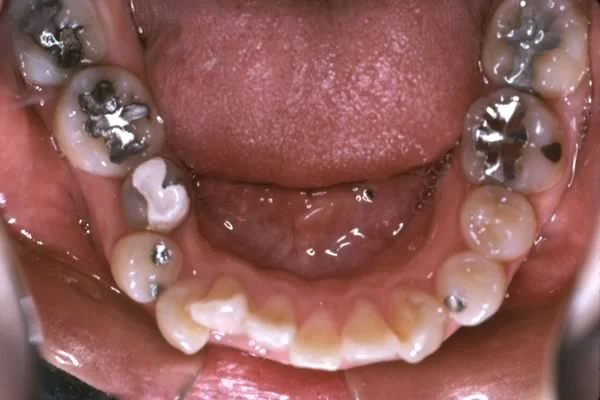 Image 3: Severe crowding prior to treatmen Image 3: Severe crowding prior to treatmen | 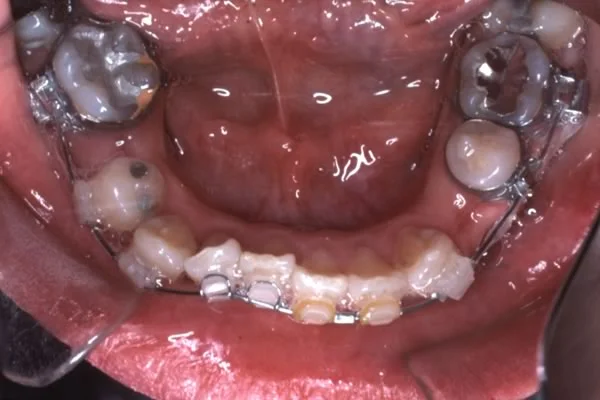 Image 4: Progress, using a superelastic NiTi wire Image 4: Progress, using a superelastic NiTi wire |
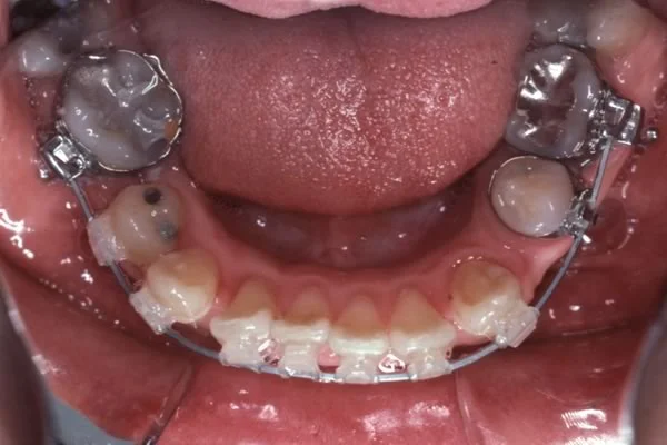 Image 5: Alignment was nearly completed without adjustment of the initial wire. Now a heavier wire can be employed as space closure begins. Image 5: Alignment was nearly completed without adjustment of the initial wire. Now a heavier wire can be employed as space closure begins. |
Design Factors in Orthodontic Appliances
Forces and Moments in Tooth Movement
Any force against an object, unless the force is directed through the object’s center of resistance, also creates a moment (image 1). A moment, by definition, is a force (grams for our purposes, newtons in scientific reports) that is delivered at a distance from the center of resistance. Its magnitude is force x distance (gm-mm). If the object is a tooth, the force has to be applied to its crown, but the center of resistance is at about the middle of the part of the root that is encased by bone. Thus we can say that not only is there a force (F) when an orthodontic spring contacts the crown of a tooth, there also is a moment of the force (MF). The effect would be to displace the crown, while tipping the tooth so that it rotates around its center of resistance (which also is the center of rotation when there’s only a single force). The periodontal ligament would be compressed maximally at the root apex on one side and at the height of the alveolar crest on the other side.
A couple, two equal forces in opposite directions, creates a pure moment (MC) that would rotate the object but not displace it. If you had equal forces in opposite directions on the corners of a box, it would just spin around (image 2).
Consider what would be required to move a tooth bodily, using a force of 100 gm (which you have already learned is about the right magnitude for bodily movement). What’s the magnitude of the moment of this force? That depends on the distance from the point where the force is applied to the center of resistance. For a maxillary incisor, it’s about 15 mm from the center of the crown (where a bracket typically would be placed) to the center of resistance. So now we have MF = 1500 gm-mm. What MC would be needed to move the tooth bodily? That’s right, you’d need 1500 gm-mm in the opposite direction to the moment created by the force against the crown (MF) so that MC cancels MF.
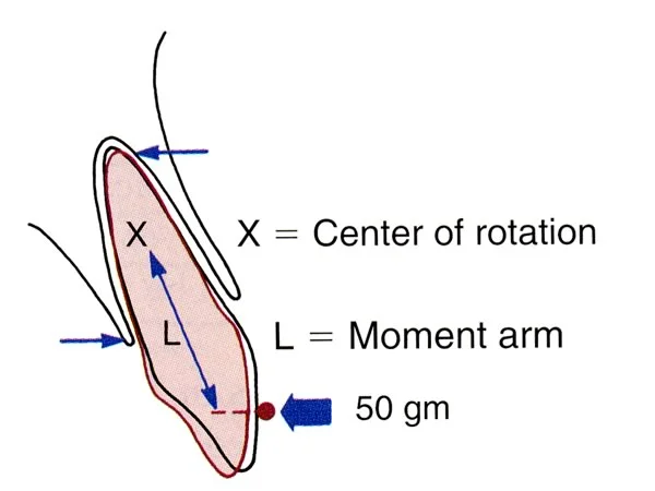 Image 1 Image 1 | 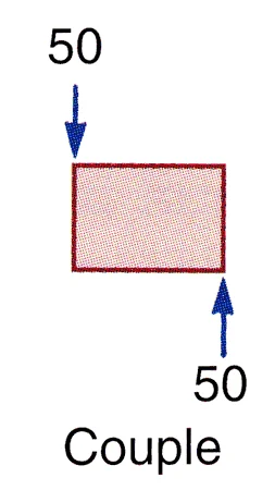 Image 2: A couple is a pure moment—so this object would spin around but would not be moved to a new location Image 2: A couple is a pure moment—so this object would spin around but would not be moved to a new location |
Effect of M
More generally, we can say that the type of tooth movement that is created will depend on the ratio of the moment of the couple (represented by a curved line in these diagrams) to the moment of the force. If MC/ MF is zero (i.e., there is no couple), the tooth tips (image 1), rotating around its center of resistance, and the root goes one way while the crown goes the other. As the MC/ MF ratio becomes positive, the tooth still tips, but now the center of rotation is displaced away from the center of resistance (image 2), so the amount that the root apex goes the other way from the crown decreases. When MC/ MF = 1, the tooth moves bodily, and now the center of rotation is displaced infinitely far away from the center of resistance (image 3). When MC/ MF becomes greater than 1, torque is created so that the root apex moves more than the crown (image 4) and the center of rotation is displaced beyond the crown.
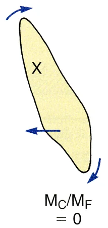 Image 1: When MC/ MF = 0 (i.e., there is no MC), the tooth tips around its center of resistance, so that the center of rotation and the center of resistance are the same. Image 1: When MC/ MF = 0 (i.e., there is no MC), the tooth tips around its center of resistance, so that the center of rotation and the center of resistance are the same. | 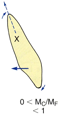 Image 2: When MC/ MF is > 0 but < 1, the tooth tips but the center of rotation is moved away from the center of resistance Image 2: When MC/ MF is > 0 but < 1, the tooth tips but the center of rotation is moved away from the center of resistance |
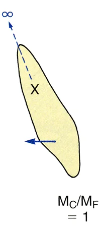 Image 3: When MC/ MF is 1, the center of rotation is displaced infinitely far away from the center of resistance, and the tooth moves bodily (translates). Image 3: When MC/ MF is 1, the center of rotation is displaced infinitely far away from the center of resistance, and the tooth moves bodily (translates). | 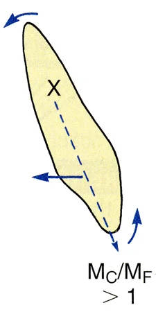 Image 4: When MC/ MF is > 1, the root apex moves more than the crown, and the center of rotation is displaced in the other direction Image 4: When MC/ MF is > 1, the root apex moves more than the crown, and the center of rotation is displaced in the other direction |
Creation of a Couple
Why are fixed appliances used for almost all orthodontic treatment, and why is a fixed appliance almost always required if you want to do anything but tip a tooth? Because it takes 2 points of contact against the crown to create a couple, and a finger spring from a removable appliance gives you only a single point of contact. This produces a force and its moment that causes the tooth to tip around its center of resistance.
With great difficulty, two finger springs contacting the tooth at different points can create a couple, but they have to push in opposite directions (image 1), and that’s so difficult to arrange that it’s rarely practical. As image 1 shows, in theory you could put one finger spring against the center of the crown of an incisor, pushing it back, and another one against the lingual surface near the incisal edge, pushing it forward. That would create a couple, and because the spring at the incisal edge is further from the center of resistance than the one pushing against the crown, its force could be less. But to get a net force of 50 grams to move the tooth, you’d have to activate the first spring to 200 gm and the second one to 150 gm. Forces of that magnitude almost surely would displace the removable appliance. The bottom line: to do anything but tip a tooth, you have to have a fixed attachment and 2 points of contact.
How much force would be placed against the corners of a bracket if you wanted to move a tooth bodily in a mesio-distal direction (to close a space between 2 teeth, for instance)? Now we have to know MF and also the distance between the equal and opposite forces. Suppose you’re using a 100 gm force, it’s 15 mm to the center of resistance, and the bracket is 4 mm wide (image 2). Then MF would be 1500 gm-mm, and you’d need a 1500 gm-mm MC to cancel it. The moment arm across the bracket would be 2 mm (the distance to the center of the bracket), and the force on each corner of the bracket to get 1500 gm-mm would be 375 gm x 2 mm + 375 gm x 2 mm. That doesn’t sound like light force, does it? If the bracket were narrower, the force on the corners of the bracket would be proportionately larger. But if this couple only cancels the moment of the force, the periodontal ligament doesn’t feel anything but the force itself.
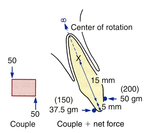 Image 1 Image 1 | 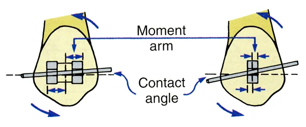 Image 2: In a fixed appliance, the wider the bracket, the longer the moment arm—so more force is needed to create a couple across a narrow bracket. Image 2: In a fixed appliance, the wider the bracket, the longer the moment arm—so more force is needed to create a couple across a narrow bracket. |
Torque
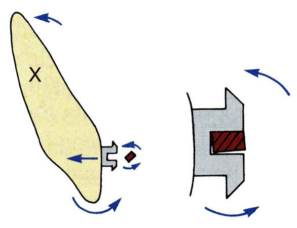
How do you create a couple to move a tooth root in a facio-lingual direction? That type of movement, of course, is torque. The edgewise appliance was created by Edward Angle in the 1920s as a torquing device, and it’s still the basis of modern orthodontics because it provides torque control. Its basis is the placement of a rectangular arch wire that is twisted so that its orientation is different from the orientation of a rectangular bracket slot into which it fits tightly. Then the twist in the wire is translated into torque for the tooth.
To create a couple within the bracket slot, the forces against the outer and inner edges of the bracket slot would have to be quite large, because the moment arm of the couple is so small. Without that heavy force within the bracket (which the periodontal ligament does not feel), you can’t create the necessary MC for torque.
Effect of Bracket Width
We already have noted the effect of bracket width on the force with which an archwire contacts the corners of a bracket to create a couple. The wider the bracket, the lower the force, because the moment arm across the bracket is longer.
If the tooth is to slide along an archwire (to close a space between the teeth), it tips until the archwire contacts the corners of the bracket. Then, if the wire doesn’t bend, a couple is created that keeps the tooth from tipping any further. The magnitude of the force that generates the couple becomes a factor in resistance to sliding. There are two sources of resistance to sliding: friction as the wire slides along the sides and base of the bracket, and contact of the wire against the corners of the bracket that creates binding.
Brackets and wires are sized by thousandths of an inch: a typical round wire size might be .016” in diameter, while a rectangular one might be .017” in one dimension, .025” in another. It’s easier if we translate those numbers into mils (milli-inches), so that .016” becomes 16 and .017” by .018” becomes 17x25. We’ll refer to wires with those numbers. For rectangular brackets, only the smaller number usually is given—if the bracket dimensions are .022 by .028” or .022 by [something else], it’s just a 22 slot bracket because the larger dimension has little effect.
For sliding, the wire must be undersized relative to the bracket. Otherwise, friction makes movement all but impossible. With an undersized wire that provides .003” clearance, however, friction can be ignored as soon as the couple is generated, because the couple creates almost all the resistance to sliding. Sliding often is done on a 19x25 steel wire in a 22 slot bracket—that’s the way you’d read about it, with the numbers in mils instead of thousandths of an inch.
The bottom line: if you want to slide a tooth along an archwire, a wider bracket is better, but friction is not an important factor when an undersized wire is used. The major source of resistance to sliding on an appropriately sized wire is the contact with the corners of the bracket, not friction (despite advertisements that say just the opposite).
Effect of Bracket Slot Size
As we have noted, the edgewise appliance was developed by Edward Angle as a torquing device. Sliding a tooth along the archwire was not part of Angle’s treatment plan. He engineered the appliance to use .0215 x .028” gold wires in a .022 x .028” slot, choosing the wire material because gold was best material available at that time. He chose to use narrow brackets to increase beam length (thereby making the wire more springy and increasing its range), and selected the wire and slot sizes to obtain the torsional properties he desired. Why torsional properties? Because the rectangular wire was twisted, not bent, when it was placed in the rectangular slot.
When stainless steel became available, the wire and slot sizes for torque changed. A 17 x 25 steel wire has torsional properties close to a 21.5 x 28 gold wire if the beam length is maximized by using narrow bracket, and to be effective it would have to be placed into a smaller slot. An 18 slot bracket typically is used for torque with a rectangular steel wire.
From this background, it’s easy to see that undersized steel wires with wider 22-slot edgewise brackets would facilitate sliding, but would make torque more difficult because full-dimension steel wires would be too stiff. With narrow 18-slot brackets and steel wires, torquing properties would be good but sliding would be more difficult. At present, about one-third of American orthodontists use 18 slot brackets and two-thirds use 22 slot. The choice is based on the trade-offs. Which do you want more: to slide on an under-sized steel wire, or torque with a full size one? It’s not that one slot size is better, it’s more that they emphasize different properties.
Contemporary Removable Appliances
Functional Appliances
Three types of removable appliances are frequently used in modern orthodontics:
- functional appliances for growth modification
- active plates with finger springs or screws for minor tooth movement, and
- clear aligners for certain types of malocclusion in adults.
The goal of a functional appliance is not to move teeth, but to guide the growth of the jaws—usually to encourage forward growth of the mandible in children with a Class II problem due to mandibular deficiency. Why is it called a functional appliance? Because the originator of this type of treatment thought it worked by changing muscle function (image 1). He called the first device of this type an activator for the same reason—it was supposed to activate the jaw muscles (the spring displaced it so that the patient had to constantly bite down to hold it in place), and this increase use of the muscles would cause growth. That turned out to be incorrect. The effects on growth are the same whether or not the child has to bite forward repeatedly, so long as the condyles are out of the fossa, but the functional appliance name has persisted.
There are many different functional appliances, as images 2-5 show.They usually are removable but can be fixed in place (image 4)—but it is more convenient for teaching purposes to discuss both types at the same time. What they have in common (for Class II children) is a construction bite that brings the mandibular condyles down and forward, out of the glenoid fossa. For a Class III child, the condyles stay in the fossa while the mandible is rotated down and back. That’s only effective if the child has a short face, so functional appliance treatment is almost totally for Class II children.
Adding springs to a functional appliance to move teeth is possible, but may be counter-productive. If you’re trying to produce forward growth of the mandible, reducing overjet by tipping upper incisors back and lower incisors forward decreases the amount of overjet reduction from growth that might be achieved.
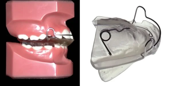 Image 1, Original activator: The activator caused the child to bite forward, and incorporated a spring to keep it from fitting tightly so that the child would have to keep biting to hold it in place—thus “activating” the muscles. Image 1, Original activator: The activator caused the child to bite forward, and incorporated a spring to keep it from fitting tightly so that the child would have to keep biting to hold it in place—thus “activating” the muscles. | 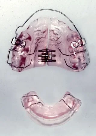 Image 2, Twin-block appliance: The twin block has separate upper and lower components, with a ramp on the lower to bring the mandible forward. A screw for maxillary expansion usually is included in the upper component. Image 2, Twin-block appliance: The twin block has separate upper and lower components, with a ramp on the lower to bring the mandible forward. A screw for maxillary expansion usually is included in the upper component. |
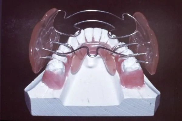 Image 3, Frankel appliance: The Frankel appliance is constructed to hold the lips and cheeks away from the dentition, and incorporates acrylic behind the lower incisors to produce a forward bite. Image 3, Frankel appliance: The Frankel appliance is constructed to hold the lips and cheeks away from the dentition, and incorporates acrylic behind the lower incisors to produce a forward bite. | 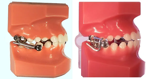 Image 4, MARA appliance: Fixed functional appliances can’t be removed by the patient. The MARA appliance (right) forces the patient to bite forward in order to bring the teeth together. It is less bulky than the older Herbst design (left) that holds the mandible forward all the time, but it may not be as effective. Image 4, MARA appliance: Fixed functional appliances can’t be removed by the patient. The MARA appliance (right) forces the patient to bite forward in order to bring the teeth together. It is less bulky than the older Herbst design (left) that holds the mandible forward all the time, but it may not be as effective. |
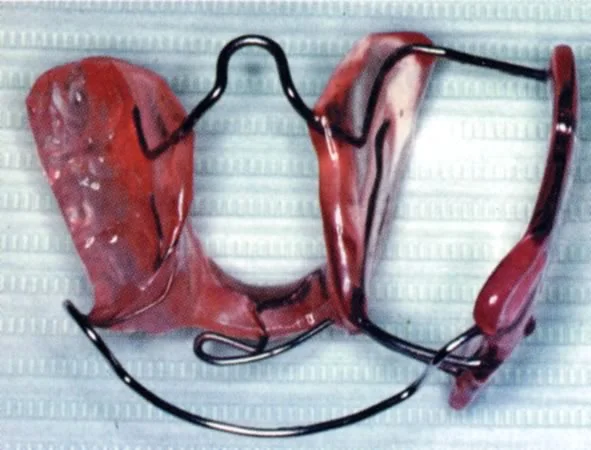 Image 5, Hybrid functional: For a patient with a jaw asymmetry, a hybrid appliance like this can be helpful. It has a bionator-type bite block on one side, Frankel-type shields on the other side, and is made using a mandibular position that improves or corrects the asymmetry. Image 5, Hybrid functional: For a patient with a jaw asymmetry, a hybrid appliance like this can be helpful. It has a bionator-type bite block on one side, Frankel-type shields on the other side, and is made using a mandibular position that improves or corrects the asymmetry. |
Functional Appliance Effects
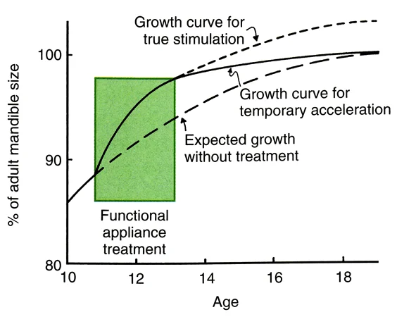
You’ve already been taught that functional appliances often do affect mandibular growth, but the major effect is an acceleration of growth rather than development of a mandible that’s significantly larger than it would have been without treatment. Let’s review that important concept.
When somebody talks to you about the wonders of treatment with a new functional appliance, keep the lesson of this graph in mind. In a child who wears the appliance faithfully (unfortunately, not all of them do that, even those with a fixed functional), the effect usually is faster growth of the mandible for a while, then a gradual tapering off of growth even if the child keeps wearing the device. In the long term, the mandible ends up quite close to the size it would have been without treatment.
So how do functional appliances work? The reaction of the soft tissues to holding the mandible forward is a backward force against the maxilla that tends to restrict its forward growth (in other words, a headgear effect). Even without springs, there’s also a force to move the lower incisors forward and the upper incisors back (a Class II elastics effect). The acceleration in mandibular growth is convenient even if it eventually tends to wear off. All these things contribute to the eventual result.
Active Plates
Active plates once were the major appliance in European orthodontics, but have never been used much in the US and Canada. Their use has declined everywhere at this point, simply because they are not efficient even though they can produce most types of tooth movement.
The “split plate” shown in image 1 shows a European approach to arch expansion, using a screw mechanism in a removable plate to produce the tooth movement. The spring properties of screws, of course, are almost nonexistent, so the screw has to be reactivated by the patient at least every few days. A one-quarter turn of the screw opens it 0.25 mm. With a split plate, the force is distributed over most of the teeth in the dental arch. Even so, a heavy force that decays rapidly is produced, just the opposite of the light continuous force that is ideal for tooth movement.
A finger spring extending from an active plate (image 2) produces more physiologic forces over a much larger range than a screw. An active plate of this design can be effective if the desired movement is tipping and the distance the tooth is to be moved is not very far (image 3).
Both types of active plates, however, really can’t compete with fixed appliances if tooth movement other than tipping is desired. We’ve already pointed out that to do anything else, you have to have two-point contact on the teeth. That’s easy with a fixed appliance, very difficult with finger springs or screws.
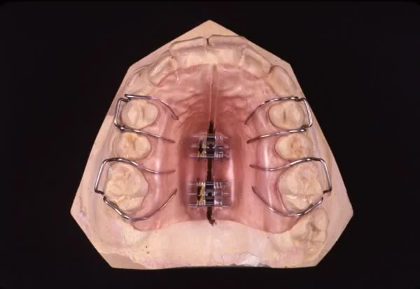 Image 1: Split-plate expansion appliance (often called a Schwarz plate after the Austrian orthodontist who popularized it). Image 1: Split-plate expansion appliance (often called a Schwarz plate after the Austrian orthodontist who popularized it). | 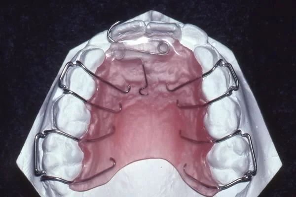 Image 2: Active plate with finger springs to correct anterior crossbite in a mixed-dentition child. Image 2: Active plate with finger springs to correct anterior crossbite in a mixed-dentition child. |
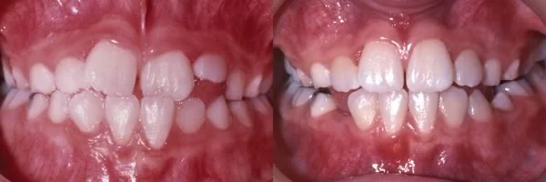 Image 3: Tooth movement achieved with the active plate seen in image 2. Image 3: Tooth movement achieved with the active plate seen in image 2. |
Clear Aligners: Invisalign
Clear aligners are “suckdown appliances” produced by vacuum-forming clear thermoplastic sheets over a dental cast. They were introduced into orthodontics originally as retainers, and still are used frequently for that purpose. But if you had a way to repeatedly move teeth a little on a cast, and then made a series of aligners after each small movement that would not quite fit intra-orally and so would move the teeth a little each time…
This patented idea has been turned into the Invisalign appliance. There is no way to account for growth changes in the dental occlusion with a series of aligners, so Invisalign is just for adults or older adolescents, but the fact that a clear aligner is almost invisible when it’s in the mouth appeals to some adults. Almost all types of tooth movement can be produced with clear aligners, so long as you’re willing to bond attachments to some teeth to improve the grip of the aligners. The attachments can be clear plastic, so they too are almost invisible.
The Invisalign technique requires a number of steps in fabricating the series of aligners:
- accurate impressions of the teeth are sent to the Invisalign laboratory, and CT scans are used to develop a digital model (image 1)
- with input from the doctor, the company’s software is used to reposition the teeth in the digital model (image 2) in a series of steps, with a new digital model for each step
- the digital models for each step are used to create a series of stereolithographic casts (image 3)
- a suckdown aligner is made to fit each of the casts (image 4)
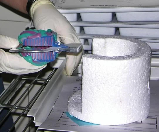 Image 1: Impressions being placed into the CT machine. Image 1: Impressions being placed into the CT machine. | 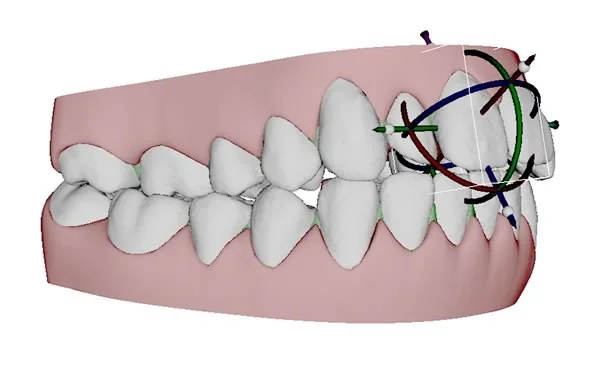 Image 2: Digital models as they look on the computer screen as a maxillary central incisor is being repositioned (0.5 mm or less in a single step). Image 2: Digital models as they look on the computer screen as a maxillary central incisor is being repositioned (0.5 mm or less in a single step). |
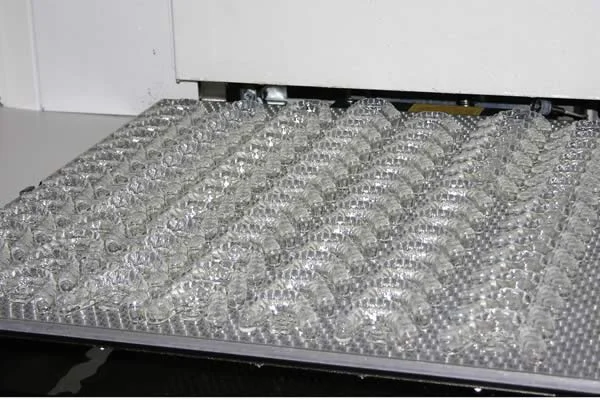 Image 3: A sequence of stereolithographic casts ready for vacuum-forming the aligners. Image 3: A sequence of stereolithographic casts ready for vacuum-forming the aligners. | 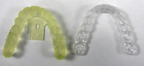 Image 4: A stereolithographic cast and the aligner made using it. Image 4: A stereolithographic cast and the aligner made using it. |
Invisalign (cont.)
Invisalign isn’t an automatic process in which the company’s technicians make all the decisions about steps in treatment. The doctor has to decide whether crowding of the teeth requires extraction (if so, Invisalign isn’t a good choice as the appliance) or can be addressed by removing small amounts of interproximal enamel (which is feasible with clear aligners) (image 1). Some types of tooth movement, especially rotation and extrusion, can be accomplished only if bonded attachments are used, and where these are placed and how many are used also is up to the doctor (image 2). The attachments can be small tooth-colored blocks of composite plastic, so they aren’t obvious.
Do you want to use Invisalign in your future general practice? You can, just as you can use fixed appliances, if you select the right patients and carefully monitor their progress. Sometimes teeth don’t move exactly as planned, and it becomes necessary to take a new set of impressions and start over. Invisalign isn’t a hands-off procedure for the clinician.
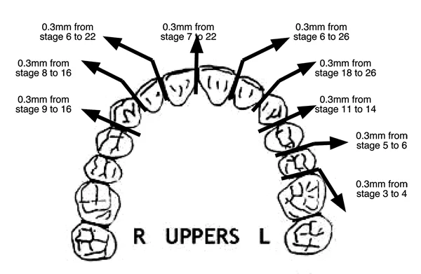 Image 1: Invisalign reproximation form, showing the amount of enamel to be removed and the stage of treatment when the resulting space will be closed. Image 1: Invisalign reproximation form, showing the amount of enamel to be removed and the stage of treatment when the resulting space will be closed. | 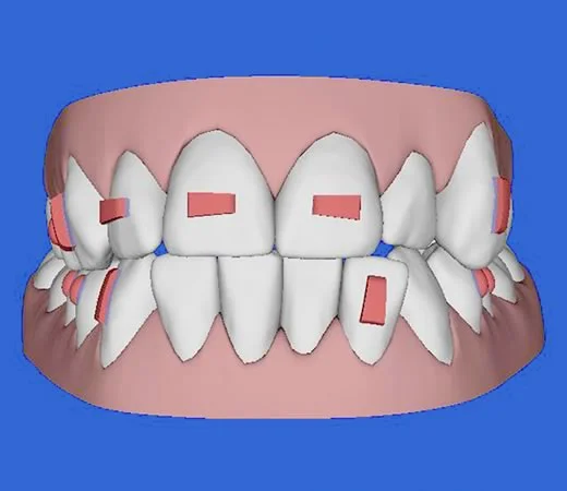 Image 2: Location of bonded attachments, as viewed on the computer screen during treatment planning. Image 2: Location of bonded attachments, as viewed on the computer screen during treatment planning. |
Invisalign Treatment
This series of images shows Invisalign treatment of a girl with a mild anterior open bite and mild crowding of the incisors. For her, elongating the upper incisors to close the open bite was appropriate because she needed greater incisor display—which is somewhat unusual in open bite patients.
To accomplish the incisor extrusion, attachments on the incisors were necessary, and removal of interproximal enamel on multiple teeth also was required to obtain ideal alignment. She had 19 upper aligners and 10 lower aligners. Treatment required 9 ½ months. (courtesy Dr. William Gierie)
 Image 1: pre-treatment smile Image 1: pre-treatment smile | 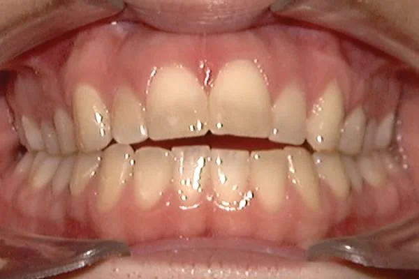 Image 2: pre-treatment occlusion Image 2: pre-treatment occlusion |
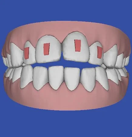 Image 3: planning for bonded attachments Image 3: planning for bonded attachments | 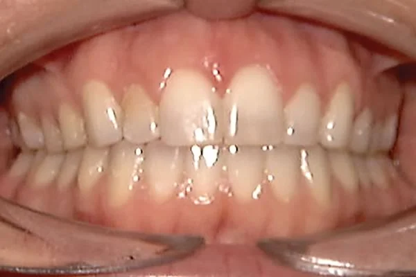 Image 4: treatment completed Image 4: treatment completed |
 Image 5: post-treatment smile Image 5: post-treatment smile |
Contemporary Fixed Appliances
Bands vs. Bonded Attachments
Angle’s edgewise appliance, which introduced the use of rectangular arch wires in a bracket with a rectangular slot, remains the basis for almost all current fixed appliances, but it has undergone a major evolution, and changes in the appliance are continuing to occur. In this section, we will briefly examine five important changes in recent years: bonded brackets rather than bands, prescription brackets (the straight-wire appliance), self-ligating brackets, computer-fabricated arch wires, and lingual appliances.
Since bonding is used widely in all types of dentistry now, its use in orthodontics requires very little discussion. The major difference between orthodontic bonding and bonding for restorative dentistry is that at some point the brackets have to be removed without damage to the enamel. Some modern restorative materials make it quite possible to bond brackets so well they can’t be removed without fracturing the enamel—so using them for orthodontic bonding would be a major mistake.
The major indication now for bands is a need for greater strength, particularly when heavy force will be encountered. A good example is when a patient will be inserting and removing a headgear (images 1, 2)- the patient probably would break a bonded attachment loose. Bands also are needed to support a lingual arch (image 3). More generally, bands often are used on first molars and sometimes on second molars in a complete fixed appliance (images 4, 5), while all other teeth have bonded attachments—but bonded attachments for molars are quite feasible for many patients.
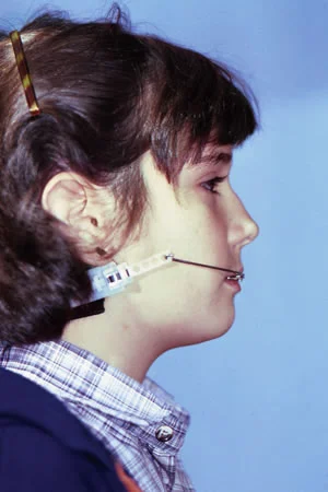 Image 1, Cervical headgear: The force to molar teeth from a typical headgear arrangement like this one is not very heavy—but heavy force can be encountered when it is being placed or removed. Image 1, Cervical headgear: The force to molar teeth from a typical headgear arrangement like this one is not very heavy—but heavy force can be encountered when it is being placed or removed. | 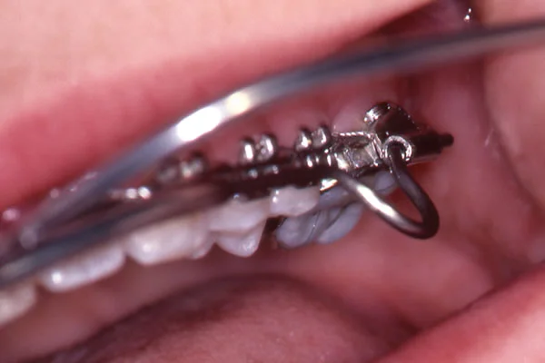 Image 2, Inner bow placement: Fitting the inner bow into the tube on a molar can be difficult for a child, who may generate heavy force in pushing it into the tube. Image 2, Inner bow placement: Fitting the inner bow into the tube on a molar can be difficult for a child, who may generate heavy force in pushing it into the tube. |
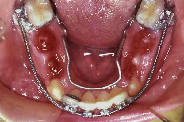 Image 3, Lingual and labial arch wires: Use of a lingual arch, especially in connection with a labial appliance, requires a band to support the buccal and lingual attachments. Image 3, Lingual and labial arch wires: Use of a lingual arch, especially in connection with a labial appliance, requires a band to support the buccal and lingual attachments. | 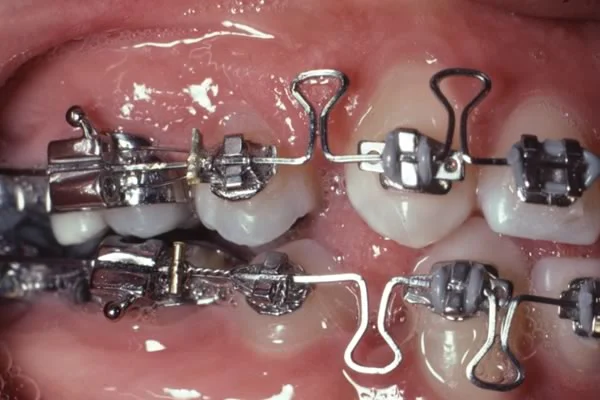 Image 4, Complete fixed appliance: Note the use of bands on the molars, with bonded brackets on other teeth, in this patient for whom premolar extraction spaces are to be closed. Image 4, Complete fixed appliance: Note the use of bands on the molars, with bonded brackets on other teeth, in this patient for whom premolar extraction spaces are to be closed. |
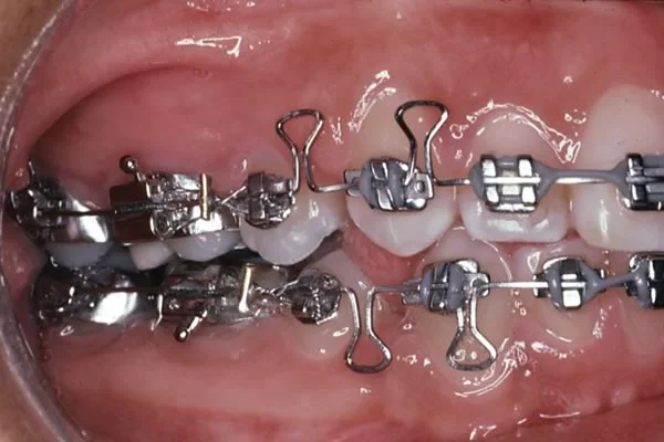 Image 5, Space closure completed: Space closure completed. Loops for space closure require arch wires with a close fit in the bracket. For this patient, 18 slot narrow brackets were used, and both the force and moment for bodily movement were generated by loops in 16x22 steel arch wires. Image 5, Space closure completed: Space closure completed. Loops for space closure require arch wires with a close fit in the bracket. For this patient, 18 slot narrow brackets were used, and both the force and moment for bodily movement were generated by loops in 16x22 steel arch wires. |
Prescription Brackets: the Straight-Wire Appliance
The original edgewise appliance used the same bracket on every tooth. This required careful formation of the arch wires to compensate for the different thickness of adjacent teeth, different inclination of the crowns, and control of facio-lingual root position.
When bonded brackets came into common use, it was feasible to produce different brackets for each type of tooth and to vary the thickness of the bracket, the inclination of the bracket slot and the torque of the slot. This didn’t eliminate bending wires, but it greatly reduced the amount of wire bending that was necessary prior to the final finishing stage. That, of course, greatly increased efficiency. It was the final step in establishing the modern edgewise appliance as the one used by almost all orthodontists now.
The effect of varying the thickness of the bracket base is shown in image 1—it can eliminate the in-out bends that previously had to be placed in every archwire. Changing the orientation of the bracket slot for the maxillary incisors eliminated the need to place bends in the wire to obtain the proper inclination of the teeth (images 2 and 3). The torque orientation of the slot eliminated the need to have twists in every rectangular wire to prevent unwanted torque movements (image 4).
 Image 1: With the original edgewise appliance, in-out bends were needed with each archwire in both the upper and lower arches to compensate for the varying thickness of the teeth. These bends can be eliminated if the thickness of the bracket base is varied. Image 1: With the original edgewise appliance, in-out bends were needed with each archwire in both the upper and lower arches to compensate for the varying thickness of the teeth. These bends can be eliminated if the thickness of the bracket base is varied. | 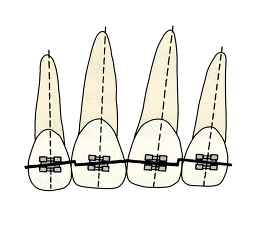 Image 2: Bends in the archwire like these, to obtain mesio-distal inclination of the roots of teeth, can be eliminated if the inclination of the bracket slot is varied. Note that different bracket inclinations are required on the left and right sides, so the left incisors would require different brackets from the right incisors. Image 2: Bends in the archwire like these, to obtain mesio-distal inclination of the roots of teeth, can be eliminated if the inclination of the bracket slot is varied. Note that different bracket inclinations are required on the left and right sides, so the left incisors would require different brackets from the right incisors. |
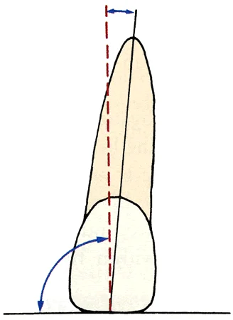 Image 3: In the modern edgewise appliance, the bracket slot is perpendicular to the long axis of the tooth, not parallel to the incisal edge. Image 3: In the modern edgewise appliance, the bracket slot is perpendicular to the long axis of the tooth, not parallel to the incisal edge. | 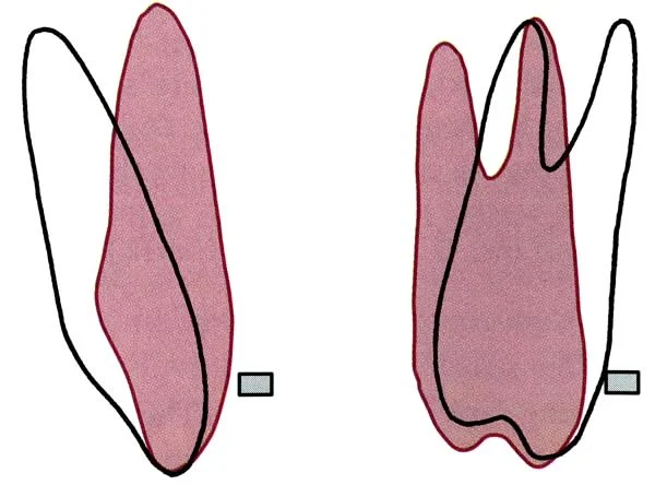 Image 4: Unless the facio-lingual orientation of the bracket slot matches the desired root orientation, twist bends are required in each rectangular archwire to prevent the teeth from becoming too upright. Image 4: Unless the facio-lingual orientation of the bracket slot matches the desired root orientation, twist bends are required in each rectangular archwire to prevent the teeth from becoming too upright. |
Self-Ligating Brackets
It’s obviously important to hold arch wires in the brackets of a fixed appliance. A pin across the front of the bracket was used in Angle’s predecessor to the edgewise appliance, and a similar system was used in the Begg appliance. Wire ligatures were used with the original edgewise appliance. In modern treatment, these have been largely superceded by elastomeric modules (Alastics).
Some sort of built-in cap was offered in a number of variations of the edgewise appliance throughout the 20th century, and this idea has been widely adapted recently. The current self-ligating brackets can be placed into three categories: active clip, active-passive clip, and passive (rigid) clip. All of them also have a prescription built into the bracket, so they are modifications of the straight-wire concept.
In an active-clip bracket (image 1), the springiness of the clip would add to the springiness of the wire, reducing the force against a tooth during initial alignment. That was more important before superelastic wires became available but still can be desirable.
It is possible to make a bracket with a clip that is active while teeth are being aligned initially, but no longer forces the wire into the bracket after alignment is complete (image 2). Almost all active clip brackets have been modified to operate in this way, and active-passive clip brackets are the most widely used type now. A variant of the active / passive design has spring clips that keep the wire within the bracket, which are passive after initial alignment is completed (image 3).
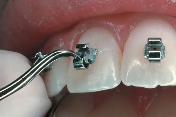 Image 1, Speed bracket: Speed (active-clip) bracket, with the clip open. Image 1, Speed bracket: Speed (active-clip) bracket, with the clip open. | 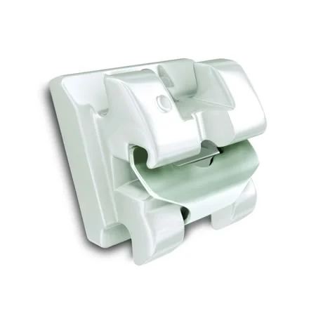 Image 2, In-Ovation bracket: InOvation bracket, with clip that catches on a ledge so that it is not active after initial alignment. Image 2, In-Ovation bracket: InOvation bracket, with clip that catches on a ledge so that it is not active after initial alignment. |
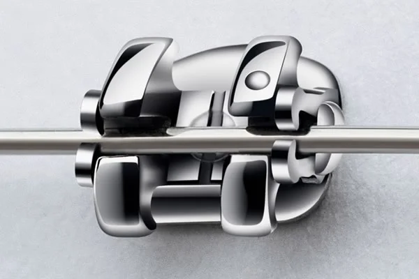 Image 3, SmartClip bracket: These brackets use NiTi springs on both ends to retain the wire. Since these springs are active only at the very beginning of treatment (if then), this can be considered an active-passive clip that is close to being entirely passive. Image 3, SmartClip bracket: These brackets use NiTi springs on both ends to retain the wire. Since these springs are active only at the very beginning of treatment (if then), this can be considered an active-passive clip that is close to being entirely passive. |
Self-Ligating vs. Conventional Brackets
A passive-clip bracket, the third type of self-ligating bracket, has a rigid cap and depends entirely on the springiness of the wire at all stages of treatment (images 1 and 2).
In the first years of the 21st century, passive-clip self-ligating brackets were advertised heavily by their major producer with the claims that they produced faster tooth movement and different outcomes from conventionally-ligated brackets, primarily by reducing friction as the bracket slid along a wire (or a wire slid through a bracket, which would be the same). This assumed that resistance to sliding is largely due to friction—but in fact elastic binding created by contact of the wire against the corners of the bracket is much more important.
Laboratory studies of resistance to sliding when there was contact of the wire with the bracket corners, as there would be in the mouth, showed no significant differences between conventional and self-ligating brackets (image 3). Note that there is little resistance to sliding when small superelastic wires are used, greater resistance with larger rectangular wires, and no differences among the types of self-ligating brackets. By 2010 a series of randomized clinical trials with human subjects had discredited essentially all the advertising claims for superior performance of passive self-ligating brackets.
In summary, evidence now shows that self-ligating brackets of all types do not change orthodontic treatment outcomes significantly. The good news is that they all perform just as well as conventionally-ligated brackets, and therefore are quite acceptable in routine use. The decision as to the type of ligation, therefore, is entirely a practice management one, based on what the doctor and staff prefer to use.
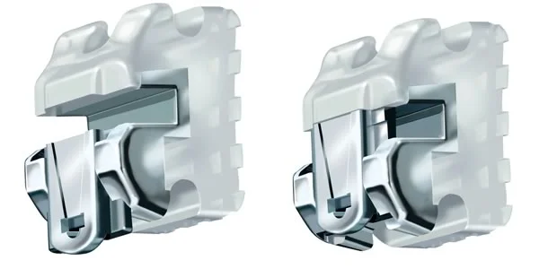 Image 1, Damon bracket: Damon bracket, with a rigid clip that cannot force the wire against the bottom of the bracket. Image 1, Damon bracket: Damon bracket, with a rigid clip that cannot force the wire against the bottom of the bracket. | 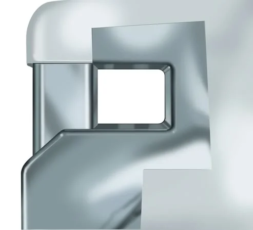 Image 2, Passive self-ligating bracket closed: A passive self-ligating bracket is equivalent to a tube when closed. Image 2, Passive self-ligating bracket closed: A passive self-ligating bracket is equivalent to a tube when closed. |
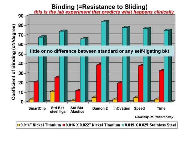 Image 3, Resistance to sliding: This laboratory data, obtained when brackets are allowed to tip so that the wire contacts the corners of the bracket, predicts that self-ligation would make no difference in resistance to sliding—which has been confirmed in studies of clinical outcomes. Image 3, Resistance to sliding: This laboratory data, obtained when brackets are allowed to tip so that the wire contacts the corners of the bracket, predicts that self-ligation would make no difference in resistance to sliding—which has been confirmed in studies of clinical outcomes. |
Custom Prescription Brackets
The prescription of a straight-wire bracket—the bracket base thickness, inclination of the slot, and torque orientation—carries with it assumptions about the morphology of the tooth and about where the bracket will be placed on the tooth. A number of prescriptions have been offered by different manufacturers, all of which are based on measurements from a large number of extracted teeth.
The result is what you’d expect: the prescription works very well for patients whose teeth closely resemble what is sometimes called “California average”. The major manufacturers are in southern California, and that’s where they collected the teeth to generate their average measurements. The further your patient is from that average, the more wire bending you’d have to do using the standard prescription. There are now prescriptions based on samples of teeth from other areas (an Asian prescription, for instance), but it’s still the case that the prescription won’t work very well for individuals who are outliers in the normal bell-shaped curve.
In this era of computer-assisted fabrication of almost everything, it’s technically possible to produce “the ultimate straight wire appliance” by producing a special custom-prescription bracket for every tooth of a specific individual, and custom archwires to produce the desired arch form and tooth positioning.
This is done using a 3-D scan of accurate dental casts to produce a digital virtual model (image 1), and using special software to reset the teeth to ideal position (image 2). Then it is possible to contour the bracket base for a precise fit at a certain point on each tooth and to cut the bracket slot with the exact prescription to place that tooth in ideal position at the end of treatment (image 3). Bonding jigs so that the bracket is placed in exactly the planned position on the tooth are critically important (image 4). Bracket positions may appear to be somewhat different from where they are usually placed (image 5), but the custom archwires will bring them very close to the planned alignment and occlusion.
Is that the way of the future? Possibly, despite the obvious problems created by loss of a bracket (the records are on file at the manufacturer, so you can get a new one in a week or two) and by problems in getting the bracket in exactly the right place on the tooth (positioning jigs are not as precise as ideal). At the finishing stage some adjustment of the arch wire may be necessary, so the best description is that custom brackets minimize rather than eliminate wire bending.
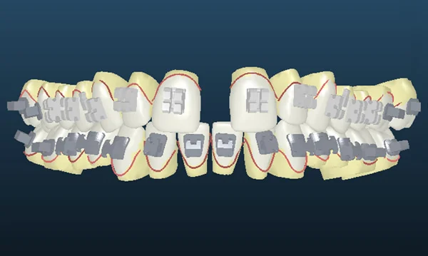 Image 1, Virtual model: For this patient with a wide maxillary central diastema and improper occlusal relationships, accurate dental casts were scanned into computer memory to create a virtual model. Image 1, Virtual model: For this patient with a wide maxillary central diastema and improper occlusal relationships, accurate dental casts were scanned into computer memory to create a virtual model. | 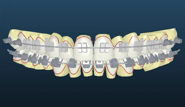 Image 2, Virtual set-up: Then the teeth were reset into the desired relationship using proprietary software. Image 2, Virtual set-up: Then the teeth were reset into the desired relationship using proprietary software. |
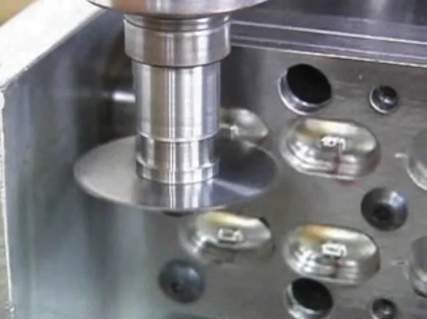 Image 3, Cutting custom bracket slots: The digital data are used to mill a custom prescription bracket for each tooth. Image 3, Cutting custom bracket slots: The digital data are used to mill a custom prescription bracket for each tooth. | 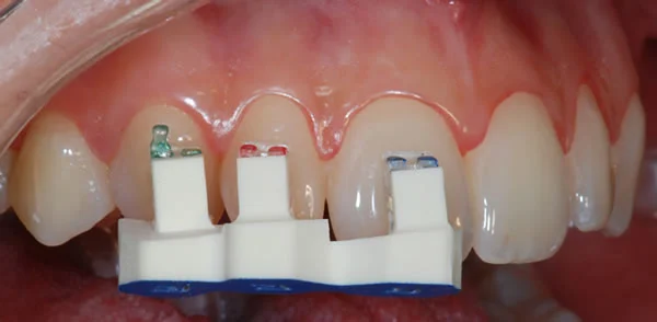 Image 4, Bonding jigs: Bonding jigs are fabricated so that the bracket can be bonded precisely in the planned location. Image 4, Bonding jigs: Bonding jigs are fabricated so that the bracket can be bonded precisely in the planned location. |
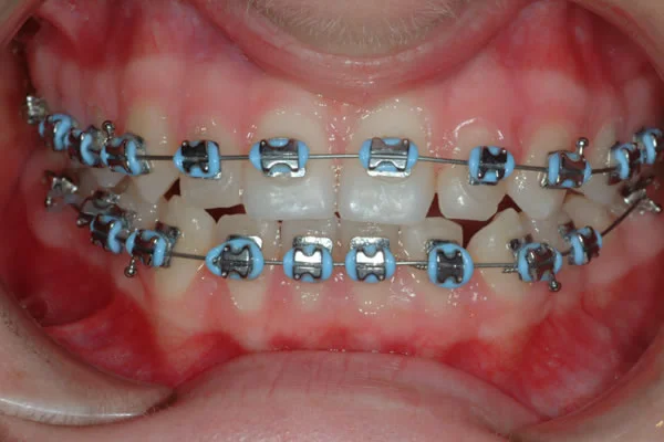 Image 5, Custom brackets in use: The appliance in the mouth. Note the vertical position of the maxillary central incisor brackets, altered from the usual location to obtain ideal display of these teeth. Image 5, Custom brackets in use: The appliance in the mouth. Note the vertical position of the maxillary central incisor brackets, altered from the usual location to obtain ideal display of these teeth. |
Computer-Fabricated Arch Wires
Custom brackets for each tooth and arch wires that are formed only to the desired arch form are one way to reduce wire bending to a minimum if not totally eliminate it. An alternative approach, now commercially available, is to use “plain vanilla” brackets with no prescription (or any prescription, so long as it is known), and then fabricate the necessary rectangular arch wires with a computer robot.
The technique requires a digital model (image 1), and at present this is achieved via an intra-oral scan after the teeth have been brought into initial alignment with small round superelastic wires. If a CT scan is available for the patient, it can substitute for the intraoral scan. Small round superelastic wires that have standard arch forms can be used for the initial alignment. The 3-D information from the scan is sent to the company’s laboratory, and a digital model produced from the scan is used with input from the doctor to set the teeth in the desired final position. Then a wire-bending robot (image 2) forms a sequence of rectangular arch wires to accomplish the changes in the digital model (images 3 and 4).
It seems quite likely that either the custom brackets approach or the computer-formed arch wire approach will win this contest between alternate CAD-CAM methods. At this point it’s too early to know how it will turn out. Which would you bet on?
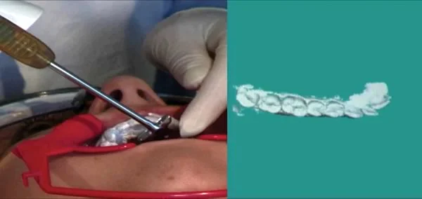 Image 1: Intra-oral laser scan, to produce a digital model of the dental Image 1: Intra-oral laser scan, to produce a digital model of the dental | 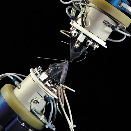 Image 2: Computer-controlled wire-bending robot Image 2: Computer-controlled wire-bending robot |
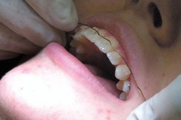 Image 3: Computer-formed arch wire before insertion Image 3: Computer-formed arch wire before insertion | 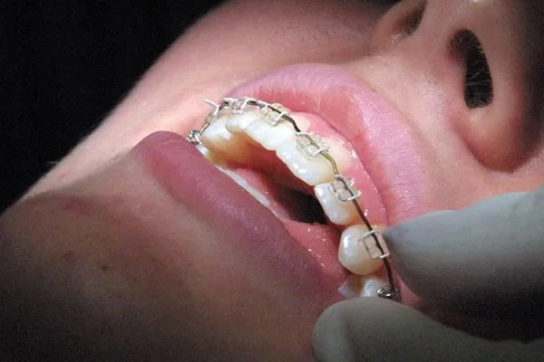 Image 4: Arch wire after insertion Image 4: Arch wire after insertion |
Lingual Appliances
Could you put an effective fixed appliance on the lingual rather than the facial surface of the teeth? Obviously you could—if the patient could tolerate it and if the doctor could get to it to adjust it.
A successful lingual appliance is a 21st century phenomenon, although efforts to develop such an appliance started many years before the turn of the century. Three major problems had to be overcome:
- bonding a thin bracket to the variable lingual surfaces of the teeth
- inserting a rectangular wire into a rectangular slot without great difficulty (disturbing the tonsils in doing so is not good!)
- forming the arch wire, which requires major bends to compensate for tooth thickness and careful use of tilt and torque
Computer-assisted appliance fabrication provided solutions to all three problems. Using scans of dental casts, it is possible to generate a bonding pad for each individual tooth (image 1). That has the advantage that the pad fits onto the lingual surface in only one position, so you can put it back accurately if it comes off. Then low-profile brackets are attached to the bonding pads, and the appliance is ready for intra-oral bonding (image 2). The brackets, which have a rectangular slot that opens to the top rather than the side so that the wire can be dropped in from the top after slipping it into a tube on the last molar, are the same for each tooth.
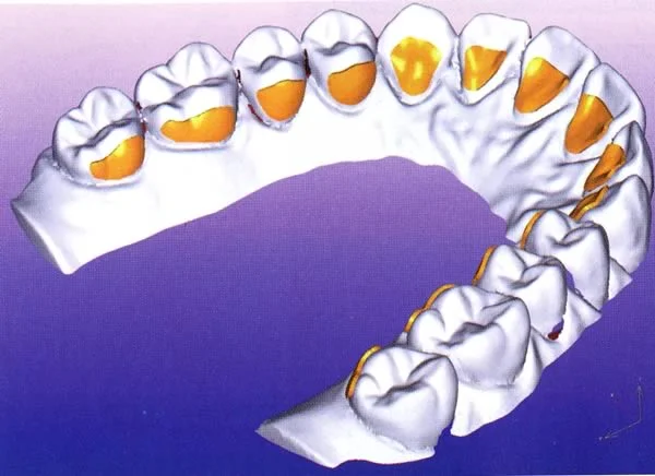 Image 1: Bonding pads for each tooth, before brackets are mounted on the pads Image 1: Bonding pads for each tooth, before brackets are mounted on the pads | 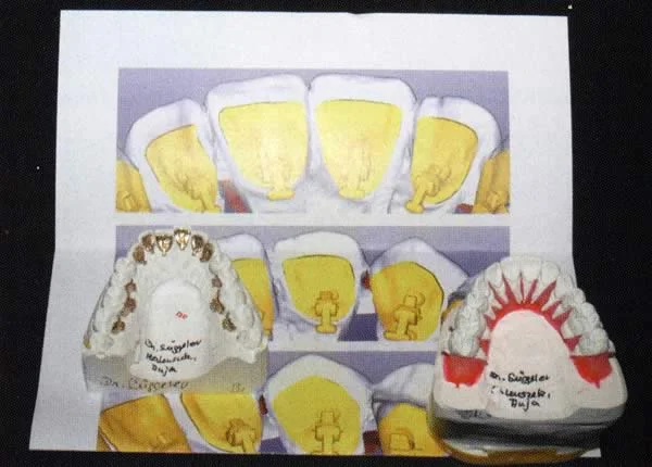 Image 2: Low-profile brackets mounted on the bonding pads Image 2: Low-profile brackets mounted on the bonding pads |
Lingual Appliances (cont.)
Now, how do you form the lingual arch wire? The teeth are reset into ideal occlusion, and a wire-bending robot is used to provide the exact bends needed in the arch wires for that individual patient (images 1 and 2).
The resulting appliance is at least reasonably tolerable for the patient, and it allows the treatment of all types of malocclusion. It’s the invisible appliance for patients whose problems are too severe to treat with Invisalign, and it is more precise and predictable than what can be achieved with the series of aligners. Laboratory costs are about the same for Invisalign and this approach to lingual orthodontics (expensive for both).
Because both the bracket slots and wires are formed to tighter tolerances in the Incognito lingual system than any current labial appliances, greater precision of tooth positioning is theoretically possible. A careful superimposition of the set-up with the actual outcome in a sample of 54 consecutive patients showed that the differences between expected and actual outcomes really were quite small. Image 3 (courtesy of Dr. Dan Grauer) shows the distribution of changes in the torque orientation of all the teeth. Similar charts were made for all 3 planes of space and all 3 orientations, i.e., locating each tooth with 6 degrees of freedom.
Studies of this type have not yet been accomplished for the custom-bracket and computer-formed facial-arch-wire methods, so how close the treatment outcomes with these techniques come to the virtual set-ups is not known. Note in image 3 that the precision of torque orientation for the 2nd molars was not as good as for other teeth, probably because the last segment of a continuous arch wire functions as a cantilever beam. Compensation for this can be built into the arch wire fabrication software. It is apparent that comparing actual to planned outcomes will be an important tool in improving the software algorithms for robotic forming of arch wires, whether the wires go on the facial or lingual surface of the teeth.
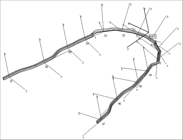 Image 1: Computer-formed archwires can have complex but precisely oriented bends, as needed to obtain the same occlusion as the ideal set-up Image 1: Computer-formed archwires can have complex but precisely oriented bends, as needed to obtain the same occlusion as the ideal set-up | 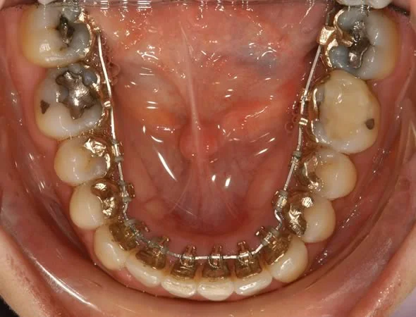 Image 2: Rectangular lingual archwire, formed by the computer-controlled wire bending robot, to produce the final detailed positioning of teeth Image 2: Rectangular lingual archwire, formed by the computer-controlled wire bending robot, to produce the final detailed positioning of teeth |
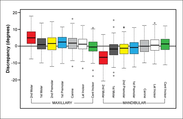 Image 3, Precision in torque: The difference in inclination (torque) between the set-up used to fabricate the lingual arch wires and the actual outcome. Each colored box shows the deviation for the median 50% of the patients. Range and extreme outliers are shown by the whisker lines and open circles, respectively. Image 3, Precision in torque: The difference in inclination (torque) between the set-up used to fabricate the lingual arch wires and the actual outcome. Each colored box shows the deviation for the median 50% of the patients. Range and extreme outliers are shown by the whisker lines and open circles, respectively. |
Self-Test Referral
The self-test section of this program is designed to help you be sure you have understood the material.
Now that you have gone through the module, do the assigned reading in Contemporary Orthodontics(pages 347-382 in 5th ed.; pages 395-429, 4th ed.) Then take the self-test, and use it as a guide for further study and review.
Copyright 2013, UNC Dept. of Orthodontics
Self-Test
Question 1
(A) Gold wires rarely are used in modern orthodontics because (B) the price of gold increased greatly in the second half of the 20th century.
- A true, B true, A and B related
- A true, B true, A and B not related ✓
- A true, B false
- A false, B true
- A and B false
Correct
You’re right, both statements are true but they aren’t related. The strength and spring qualities of stainless steel had led to the replacement of gold by steel wires even before the cost difference increased greatly. At any price, gold is no longer competitive as a material for orthodontic wires.
Incorrect
No, that’s wrong. Both statements are true but they aren’t related. The strength and spring qualities of stainless steel had led to the replacement of gold by steel wires even before the cost difference increased greatly. At any price, gold is no longer competitive as a material for orthodontic wires.
Question 2
Which of the following is the correct description of the elastic limit for an orthodontic arch wire? the point at which
- it deviates from totally elastic behavior
- it deviates at a measurable level ✓
- superelastic behavior is first noted
- it begins to fail
- it breaks
Correct
That’s right. Yield strength, measured in the laboratory as the lowest point on a stress-strain curve at which a measurable amount of permanent bending can be observed, typically is used to describe the elastic limit of the wire. The proportional limit is an alternative term, and sometimes elastic limit and proportional limit are used interchangeably.
Incorrect
No, that’s incorrect. Yield strength, measured in the laboratory as the lowest point on a stress-strain curve at which a measurable amount of permanent bending can be observed, typically is used to describe the elastic limit of the wire. The proportional limit is an alternative term, and sometimes elastic limit and proportional limit are used interchangeably.
Question 3
On a stress-strain curve, which of the following reflects the formability of a wire (the extent to which you can permanently deform it while bending it)?
- slope of the linear portion of the curve
- area under the linear portion of the curve
- distance along the stress axis (x axis) to the failure point
- area under the curve between ultimate strength and failure point
- area under the curve between yield strength and failure point ✓
Correct
That’s right, the area under the curve between yield strength (where permanent deformation starts, for all practical purposes) and failure point (where the wire breaks) describes the formability of the material.
Incorrect
No, that’s wrong. The area under the curve between yield strength (where permanent deformation starts, for all practical purposes) and failure point (where the wire breaks) describes the formability of the material.
Question 4
For a superelastic NiTi wire, what portion of a stress-strain graph represents the portion of the curve that contributes most of the force applied to a tooth?
- initial linear portion, loading
- initial plateau, loading
- second linear portion, unloading
- second plateau, unloading ✓
- final linear portion, unloading
Correct
That’s right. The superelastic plateau is the most important part of a graph that shows the force delivered to a tooth by a superelastic spring or section of an archwire—but it’s the lower of the two plateau curves, the unloading section of the curve.
Incorrect
No, that’s incorrect. The superelastic plateau is the most important part of a graph that shows the force delivered to a tooth by a superelastic spring or section of an archwire—but it’s the lower of the two plateau curves, the unloading section of the curve.
Question 5
It’s quite effective to bend a helix in a finger spring to increase its length because (B) springiness goes up when you do this while range goes down.
- A true, B true, A and B related
- A true, B true, A and B not related
- A true, B false ✓
- A false, B true
- A and B false
Correct
That’s correct, the first statement is true but the second is false. Springiness goes up more than strength goes down when you lengthen the spring by bending a helix, and range also increases, not decreases.
Incorrect
No, that’s wrong. The first statement is true but the second is false. Springiness goes up more than strength goes down when you lengthen the spring by bending a helix, and range also increases, not decreases.
Question 6
For any elastic material, what determines the smallest size of wire that you could use to form a finger spring? It’s inherent
- strength ✓
- springingess
- range
- resilience
- 1,2 and 3
Correct
That is correct. The strength of the material determines the smallest size of wire that you can use, because if it deforms permanently when you activate a spring made from it or the patient bites against it, it will be ineffective. Once you have a wire that’s strong enough, you can improve its spring properties by lengthening the beam—which of course is what is done in fabricating most finger springs.
Incorrect
No, that’s incorrect. The strength of the material determines the smallest size of wire that you can use, because if it deforms permanently when you activate a spring made from it or the patient bites against it, it will be ineffective. Once you have a wire that’s strong enough, you can improve its spring properties by lengthening the beam—which of course is what is done in fabricating most finger springs.
Question 7
In 1920 gold was the preferred material for orthodontic appliances. Which of the following is most likely to be the preferred material in 2020?
- new precious metal alloys
- improved stainless steel
- titanium alloys
- chrome-cobalt alloys
- composite plastics ✓
Correct
That’s right. Already composite plastic materials offer better combinations of strength, springiness and range than metal alloys, and these new materials are being used to build the most advanced airplanes. Since orthodontic technology tends to follow aerospace technology by 10-15 years, it is highly likely that composite plastics will be the preferred material for orthodontic appliances in another decade or so.
Incorrect
That’s wrong. Already composite plastic materials offer better combinations of strength, springiness and range than metal alloys, and these new materials are being used to build the most advanced airplanes. Since orthodontic technology tends to follow aerospace technology by 10-15 years, it is highly likely that composite plastics will be the preferred material for orthodontic appliances in another decade or so.
Question 8
(A) When a single force is applied against the crown of a tooth, the center of resistance and center of rotation are the same because (B) the moment of the force is determined by the distance from the point of force application to the center of reistance.
- A true, B true, A and B related
- A true, B true, A and B not related ✓
- A true, B false
- A false, B true
- A and B false
Correct
That’s right. The two statements are both true, but they don’t have a cause-and-effect relationship. The center of resistance and center of rotation are the same because there is a moment of the force, not because of what determines its magnitude. The only way to keep a force from rotating the tooth around its center of resistance is to apply the moment of a couple to counteract the moment of the force.
Incorrect
No, that’s wrong. The two statements are both true, but they don’t have a cause-and-effect relationship. The center of resistance and center of rotation are the same because there is a moment of the force, not because of what determines its magnitude. The only way to keep a force from rotating the tooth around its center of resistance is to apply the moment of a couple to counteract the moment of the force.
Question 9
Which of the following is a correct ratio if you want to torque the root of an incisor lingually?
- M
- M
- M
- M ✓
- all could be correct, depends on location of center of resistance
Correct
That’s right, torque requires a MC / MF ratio greater than 1, so that the root moves more than the crown. The location of the center of resistance has nothing to do with it.
Incorrect
No, that’s wrong. Torque requires a MC / MF ratio greater than 1, so that the root moves more than the crown. The location of the center of resistance has nothing to do with it.
Question 10
How does the formability of a superelastic NiTi wire compare to the formability of a stainless steel wire? The formability of the NiTi wire is
- much greater
- a little greater
- about the same
- a little less
- much less ✓
Correct
That’s right, the formability of superelastic NiTi wire is much less than the formability of a stainless steel wire. It’s so much less that for all practical purposes, you can’t really change the shape of the wire that you purchased from the manufacturer—quite unlike steel wire that you can readily bend to make orthodontic springs.
Incorrect
No, that’s wrong. The formability of superelastic NiTi wire is much less than the formability of a stainless steel wire. It’s so much less that for all practical purposes, you can’t really change the shape of the wire that you purchased from the manufacturer—quite unlike steel wire that you can readily bend to make orthodontic springs.
Question 11
When a rectangular arch wire is used to torque a tooth, how does the force with which the wire contacts the walls of the bracket compare to the force felt by the PDL?
- much greater ✓
- a little greater
- about the same
- a little less
- much less
Correct
That’s right, the force with which the edges of the twisted wire contact the inner and outer surfaces of the bracket is much greater than the force felt by the periodontal ligament. The wire creates a couple within the bracket, and because the moment arm from one side of the wire to the other is quite small, the equal and opposite forces to form the couple have to be quite large.
Incorrect
No, that’s incorrect. The force with which the edges of the twisted wire contact the inner and outer surfaces of the bracket is much greater than the force felt by the periodontal ligament. The wire creates a couple within the bracket, and because the moment arm from one side of the wire to the other is quite small, the equal and opposite forces to form the couple have to be quite large.
Question 12
(A) The resistance to sliding a tooth along an arch wire increases when a wider bracket is used because (B) the wider bracket allows an arch wire to create a moment across it with less force on the corners of the bracket.
- A true, B true, A and B related
- A true, B true, A and B not related
- A true, B false
- A false, B true ✓
- A and B false
Correct
That’s right, the first statement is false but the second one is true. All other things being equal, resistance to sliding decreases, not increases, when a wider bracket is used. A wider bracket allows creation of a moment to control root position with less force against the bracket corners, because the moment arm is longer. It’s the force against the bracket corners that creates almost all of the resistance to sliding.
Incorrect
No, that’s wrong. The first statement is false but the second one is true. All other things being equal, resistance to sliding decreases, not increases, when a wider bracket is used. A wider bracket allows creation of a moment to control root position with less force against the bracket corners, because the moment arm is longer. It’s the force against the bracket corners that creates almost all of the resistance to sliding.
Question 13
Which of the following types of tooth movement require 2-point contact with the crown of the tooth being moved?
- tipping
- bodily movement
- torque
- 1 only
- 2 only
- 1 and 2
- 2 and 3 ✓
- all require 2-point contact
Correct
That’s right, tipping results from one-point contact, while bodily movement and torque require two-point contact. That means that tipping is the primary outcome of treatment with a removable appliance and finger springs, while bodily movement and torque all but require a fixed appliance.
Incorrect
That’s wrong. Tipping results from one-point contact, while bodily movement and torque require two-point contact. That means that tipping is the primary outcome of treatment with a removable appliance and finger springs, while bodily movement and torque all but require a fixed appliance.
Question 14
When clear aligners are used for orthodontic treatment, which types of tooth movement require bonded attachments?
- tipping
- rotation
- extrusion
- intrusion
- 1 and 2
- 1 and 3
- 2 and 3 ✓
- 2 and 4
- 1 and 4
Correct
That’s right. With clear aligners, rotation and extrusion are almost impossible without the use of a bonded attachment on the tooth so that the aligner can get a better grip on it. Interestingly, intrusion can be accomplished with an aligner without bonded attachments because light force is all that is needed. An aligner has enough grip to do that, and also to tip teeth.
Incorrect
That’s wrong. With clear aligners, rotation and extrusion are almost impossible without the use of a bonded attachment on the tooth so that the aligner can get a better grip on it. Interestingly, intrusion can be accomplished with an aligner without bonded attachments because light force is all that is needed. An aligner has enough grip to do that, and also to tip teeth.
Question 15
Which of the following are part of the prescription for a modern straight-wire bracket?
- specific type of tooth
- base thickness
- angulation of bracket slot
- facio-lingual orientation of bracket slot
- 1 and 2
- 3 and 4
- 1, 2, and 3
- 2, 3, and 4
- all ✓
Correct
That’s right, all four of these items are part of the prescription. The basic idea for the modern bracket is that it is intended for a specific type of tooth. The thickness of the base compensates for the varying thickness of teeth (particularly the incisors and canines), thereby reducing the need for in-out bends in arch wires. The angulation of the bracket slot reduces the need for bends to obtain proper mesio-distal root position, and the facio-lingual orientation of the slot provides torque as needed to control facio-lingual root position.
Incorrect
No, that’s incorrect. All four of these items are part of the prescription. The basic idea for the modern bracket is that it is intended for a specific type of tooth. The thickness of the base compensates for the varying thickness of teeth (particularly the incisors and canines), thereby reducing the need for in-out bends in arch wires. The angulation of the bracket slot reduces the need for bends to obtain proper mesio-distal root position, and the facio-lingual orientation of the slot provides torque as needed to control facio-lingual root position.
Question 16
Which of the following correctly describe active self-ligation for an orthodontic bracket? Springiness of a clip
- adds to springiness of the archwire
- makes the wire more resilient
- effectively makes the wire stronger
- 1 only ✓
- 1 and 2
- 2 and 3
- 1 and 3
- all the above
Correct
That’s right. Active self-ligation means that the clip that holds the wire in place is springy and adds to the springiness of the wire during initial alignment. The clip, however, doesn’t change the properties of the archwire. Resilience and strength of the wire are independent of how it’s held in a bracket.
Incorrect
No, that’s incorrect. Active self-ligation means that the clip that holds the wire in place is springy and adds to the springiness of the wire during initial alignment. The clip, however, doesn’t change the properties of the archwire. Resilience and strength of the wire are independent of how it’s held in a bracket.