Radiography In Periodontology1
DR ANNA HUGHES / Dr Rincon / Prof Abbott
Introduction And Clinical Objectives2
AIM OF THE LECTURE
- To understand the diagnostic benefit and biological cost of radiographic imaging
- To understand the prerequisites for prescribing a radiological test
- Discuss the imaging modalities used in periodontology
- Interpreting radiographs for periodontal diagnosis
Principles Of Radiographic Imaging
Benefits And Limitations34
BENEFITS OF RADIOLOGY IN PERIODONTOLOGY
- Evaluation of health and pathology of hard tissues - teeth and surrounding bone.
- Essential aid in diagnosis in addition to the clinical periodontal assessment.
- Important in determining prognosis.
- Facilitates treatment planning.
- Important to exclude non-inflammatory conditions.
- Prerequisite for pre-surgical planning.
- Assists in monitoring treatment outcomes.
LIMITATIONS OF RADIOLOGICAL IMAGING
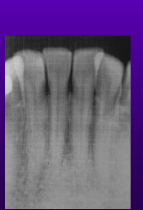
- Ionizing radiation mostly only reveals alteration in calcified tissues.
- It doesn’t reveal cellular (disease) activity.
- Shows only historical bone destruction.
- Limited value in soft tissue analysis.
- After regenerative procedures, difficult to distinguish between bone graft and regenerated bone.
Biological Costs And Radiation Effects5
BIOLOGICAL COSTS and the effects of ionizing radiation
Ionizing radiation can induce cellular and chromosomal damage in 2 main ways:
- Deterministic effect – dose has to be over a certain threshold to cause damage, severity then increases with dose – fetal abnormality, skin damage, hair loss.
- Stochastic effect – not dose dependent but risk increases with higher dose – induction of chromosomal damage which can develop into specific cancers, leukemias, salivary gland, thyroid, breast, brain. Can occur years after radiation.
- Radiation dose protection principles very important – justification, optimization (Alara), dose limitation.
Prerequisites For Radiographic Prescription6
PREREQUISITES
- Sound knowledge of anatomy and radiological anatomy in the field of view of your radiograph.
- Knowledge of the disease conditions you are looking for and its radiographic presentation.
- The principle of Alara (as low as reasonably achievable) and pros and cons of each imaging modality.
- Training in taking a good radiograph.
Imaging Modalities And Techniques
Overview Of Modalities78
-
Ionizing radiation – intra/extraoral sensors
-
Bitewings, periapicals, occlusal
-
Panoramic, cephalometric views
-
3D imaging – cone beam computed tomography
-
Multislice / multidetector computed tomography
-
Non-ionizing radiation
-
Ultrasound
-
MRI
-
Bone destruction, bone loss pattern and bone defect morphology.
-
Roots – anatomy, length, crown/root ratio, hypercementosis
-
Restorations – deficiencies, caries, overhangs
-
Calculus if abundant
-
Pulp/periapical conditions, perio-endo conditions
-
Furcations
-
Periodontal ligament space
-
Tooth impactions, root remnants, unerupted teeth
-
Any pathology of the root or adjacent structures
-
Bone deficiencies
Intraoral Radiography910
- Standard imaging modality for periodontal evaluation, mostly diagnostic of interdental bone changes
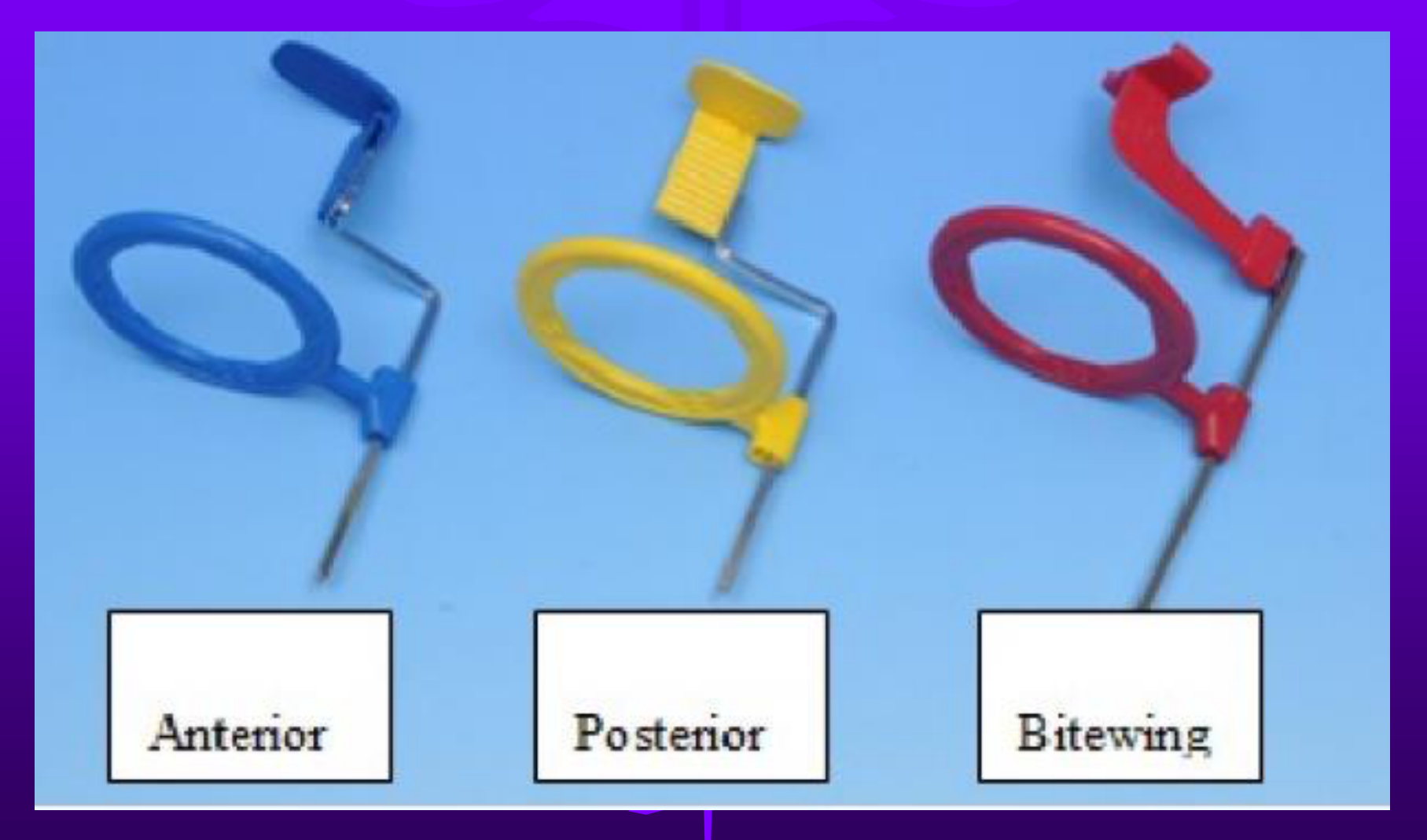
- Periapical and bitewings use various sized films / digital sensors intraorally attached to a localising ring.
- Not as accurate as 3D imaging but much lower radiation dose.
- Ideally aim to standardize technique – exposure time, film size, angulation
Periapical And Bitewing Views111213
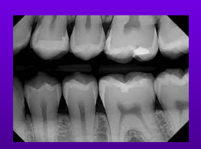
- Various sized small digital sensors positioned ideally parallel to the tooth being examined – ideal for viewing the whole root, used for evaluating periapical and periodontal/peri-implant status – even with holders you can over- or underestimate calculations
Used for caries detection and early crestal bone loss
More accurate than PAs because x-ray projection more perpendicular to teeth but records only coronal third of tooth
Ideally no overlap of teeth, cusp tips clear
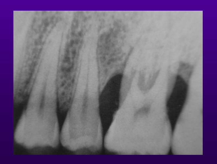
- How do you know it’s a good intraoral radiograph?
- Clear cusps of molars
- Enamel and pulp chambers seen and distinct.
- Interproximal spaces should be open.
- Interproximal contacts should not overlap (unless crowding present)
 |  |
 |
Limitations And Distortions1415
- Superimposition
- Buccal/lingual bone and roots
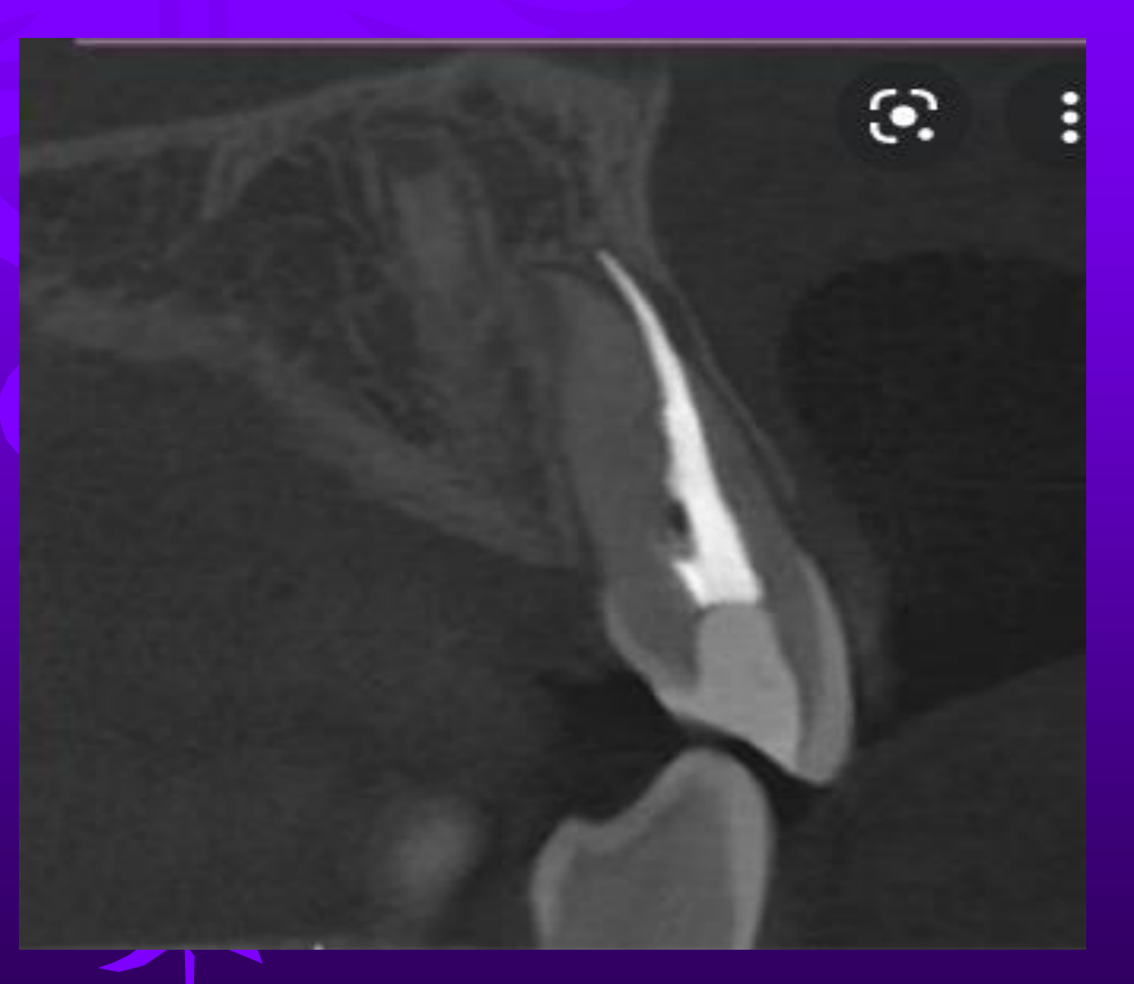
Effect of varying the angulation
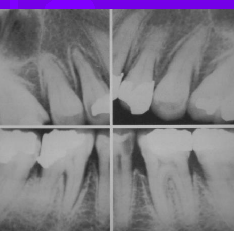
Vertical and horizontal shifting of the x-ray tube will change the configuration of the PDL space, furcation, interdental bone, position of roots
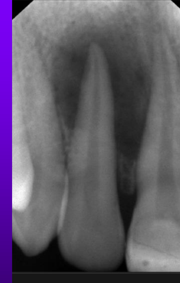
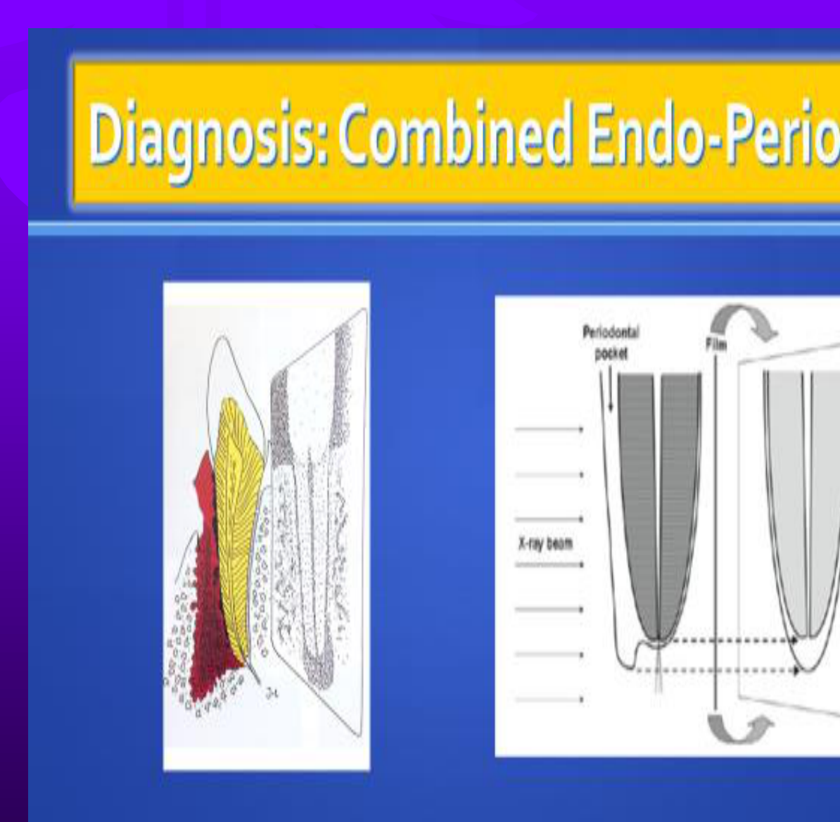
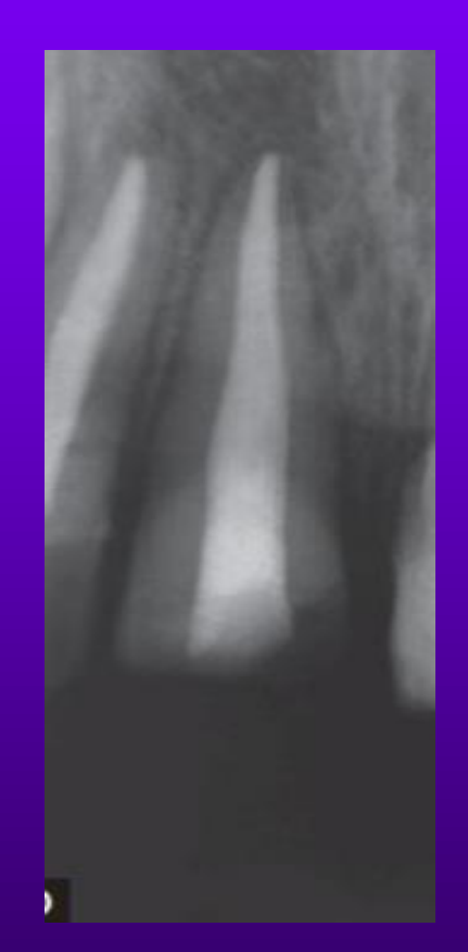
An endodontic infection? Or a severe periodontal infection?
- Or a root perforation?
 |  |
 |  |
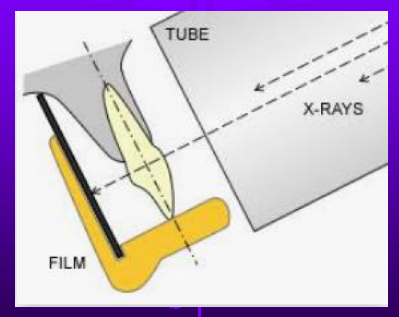
Radiographic Techniques And Tube Shifts16
Distortions – by vertical/horizontal shifting
Bisection technique:
- Increases projection
- Bone closer to crown
- Distortion of facial and lingual bone
- Long cone technique better
Mesial or distal shifting:
- Changes the shape of interdental bone
- Changes PDL space width
- Changes lamina dura
- Furcation involvement changes
Long cone parallel technique
Vertical Shift
- Increased angle
- Decreased angle
Horizontal shifts
-
Mesial
-
Distal
-
Used to separate objects that are otherwise superimposed over each other
-
Can help to indicate the “3rd dimension”
Extraoral And 3D Imaging
Panoramic And Cephalometric Radiology1718192021
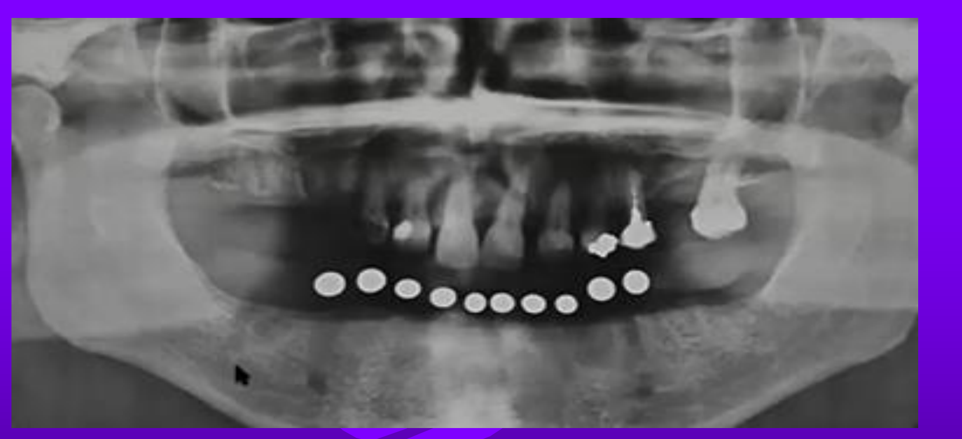
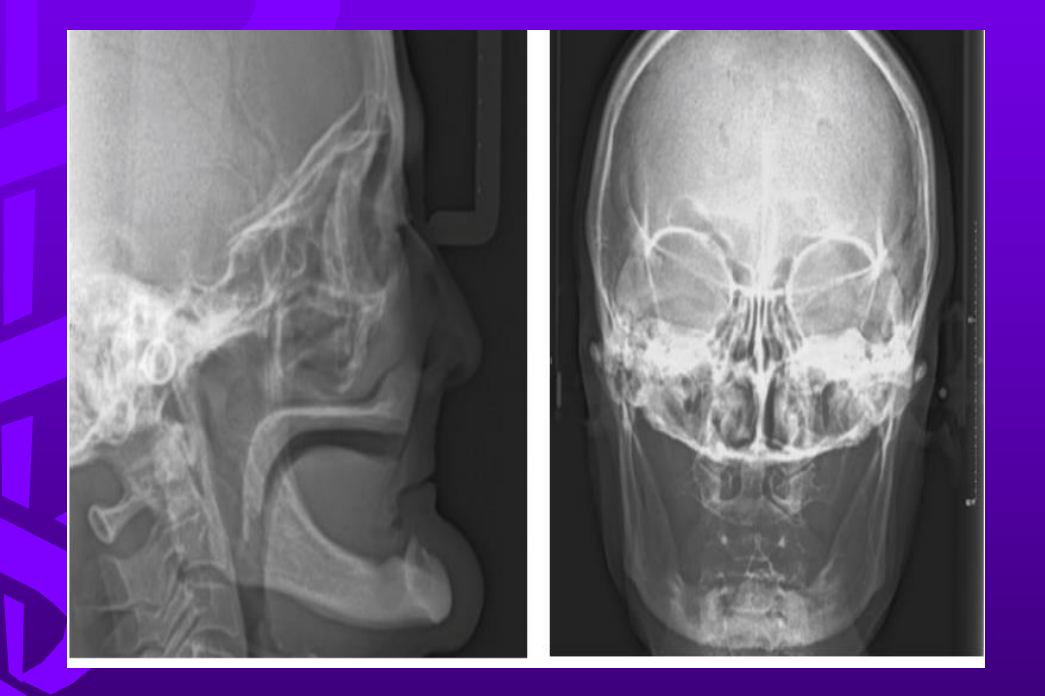
- Extraoral rotating x-ray source and image receptor moves around the patient’s head – produces a curved image of patient’s jaws, teeth, TMJ.
- Useful as a screening tool, especially if intraoral views not possible/uncomfortable.
- Problems – image magnification, ghost and double images, distortion, superimposition, low resolution
- Lower radiation dose compared to full mouth periapical radiographs
Variations in panoramic machines – magnifications are uneven and unpredictable
Image distortions, variable shortening and elongations, lingual objects more superior
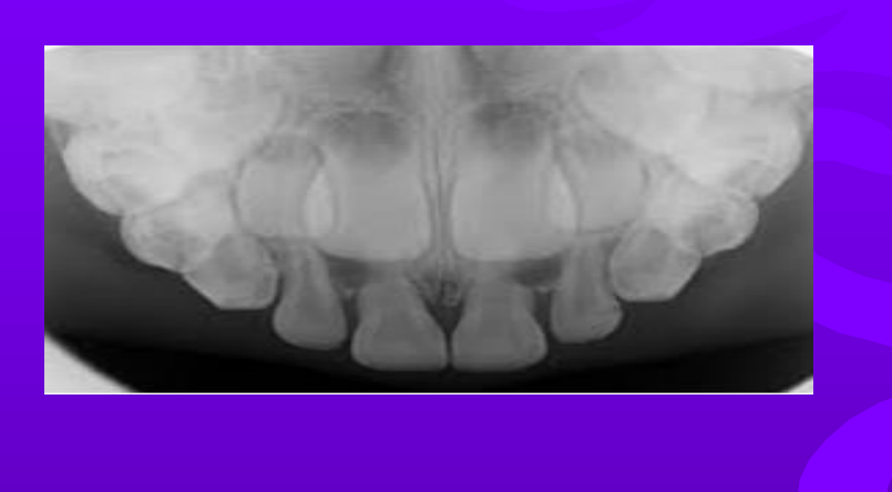
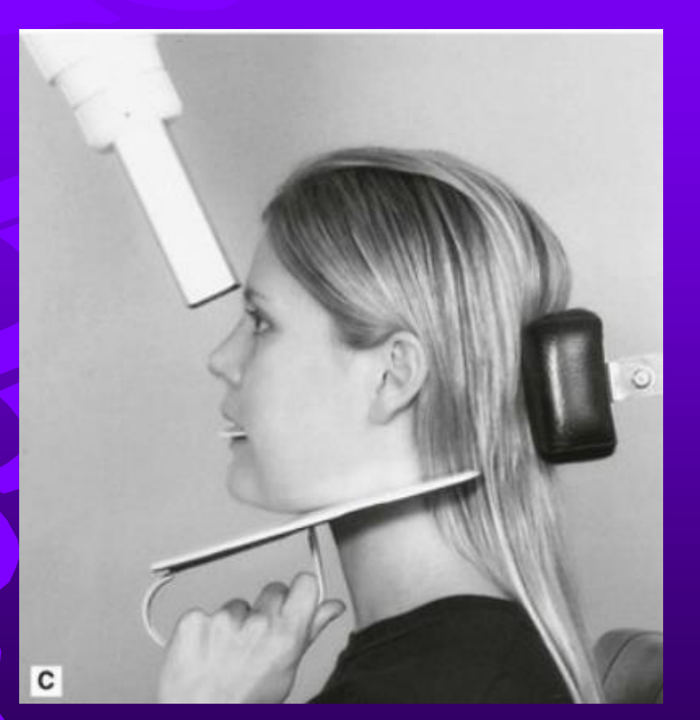
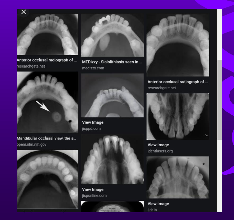
Occlusal radiographs – used in perio to locate impacted / unerupted teeth (also in dental trauma, locate bone lesions, fractures)
- More useful in orthodontic therapy and orthognathic surgery
- Occasionally used in perio for full arch implant rehabilitation
- Superimposition of structures
- Geometric alteration
- Elongation & foreshortening, even with holders
- Anatomic obstacles
- Unable to show complex root morphology
 |  |  |
 |  |
Cone Beam And Multidetector Computed Tomography22232425
- Introduced into the dental field in 1998, rapidly growing in popularity.
- Uses a cone beam to capture image in one rotation around a patient – less radiation compared to MDCT
- Spatial resolution lower than 2D images but higher by 2-8 times than a MDCT.
- Radiation dose higher than an OPG by 5-10 times (machines in envision)
- But low contrast resolution (poor for soft tissues and low density structures) – big problems with movement and metallic artifacts.
Already commonly used in medicine – fan beam x-rays to take axial slices from top to bottom.
Superior soft tissue contrast compared with cone beam.
Less accessible for dentists, high cost and radiation dose (up to 15 times more than a CBCT)
-
To determine the extent and pattern of periodontal bone loss, including infrabony defects, dehiscences, fenestrations
-
Furcation morphology – i.e. width of entrance, pattern of bone loss in furcations
-
Root morphology
-
Root fractures
-
Periapical status
-
Origin of infection
-
Pre-surgical / implant planning
-
Pre-ortho in thin phenotypes / perio patients
-
BUT INTRAOPERATIVE ANALYSIS MOST ACCURATE
-
Software available to manipulate the axial images into other planes and views (sagittal, coronal…) – MPR or multiplanar reformation
-
Software can be used to plan and form an implant surgical guide pre-op along with computer assisted treatment planning
-
CBCT not useful to monitor peri-implant bone loss (metallic artifacts) – OPG and periapicals better for interproximal bone evaluation

Comparative Radiation Doses26
- IO PA / BW = 2 uSv
- OPG = 20 uSv
- CBCT = 40-80 uSv
- Chest x-ray = 14 uSv
- Background radiation in the UK = 7 uSv/daily
- Flight – UK to US = 80 uSv
Non Ionizing Radiation Modalities272829
-
Radiofrequency pulse used in a chamber with a static magnetic field
-
Excellent for TMJ and soft tissue analysis
-
However expensive, claustrophobic, severely affected by metal artifacts
-
Increasing interest in developing its use for perio because of ability to differentiate between healthy and inflamed soft tissue
-
Uses sound waves and a transducer to generate an image.
-
Large transducer head limits current application to TMJ, salivary glands, lymph nodes, head and neck muscles, thyroid gland, carotid vessels
-
Smaller transducers more useful intraorally and currently being developed – useful for teeth and implant soft tissue measurements.
-
Not affected by metal artifacts so useful for peri-implant evaluation.
-
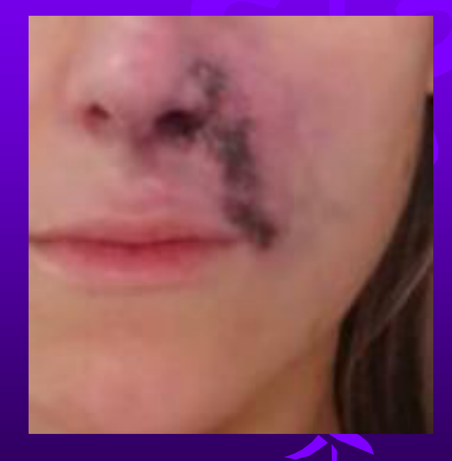
Useful for cosmetic injectables (fillers) to avoid vascular occlusion and evaluate longevity and migration of fillers.
FILLER COMPLICATIONS – VASCULAR OCCLUSION AND TISSUE NECROSIS
Radiographic Interpretation And Diagnosis
Normal Radiographic Features3031
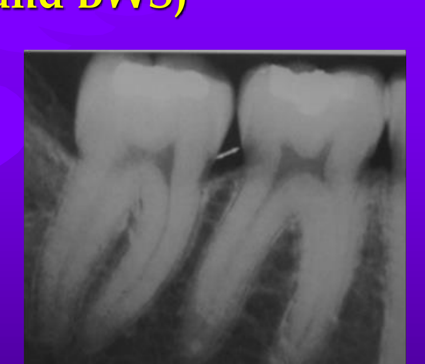
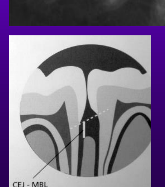
Normal Radiographical Features on a 2D Image (PA and BWS)
- Interdental bone/septa width varies between different teeth, but should be radiopaque and smooth and horizontal.
- Alveolar crest 0.5 to 2 mm to CEJ.
- Lamina dura – dense cortical bone – appears as a white line, which may or not be continuous.
- Periodontal ligament space may be widened if the teeth are mobile.
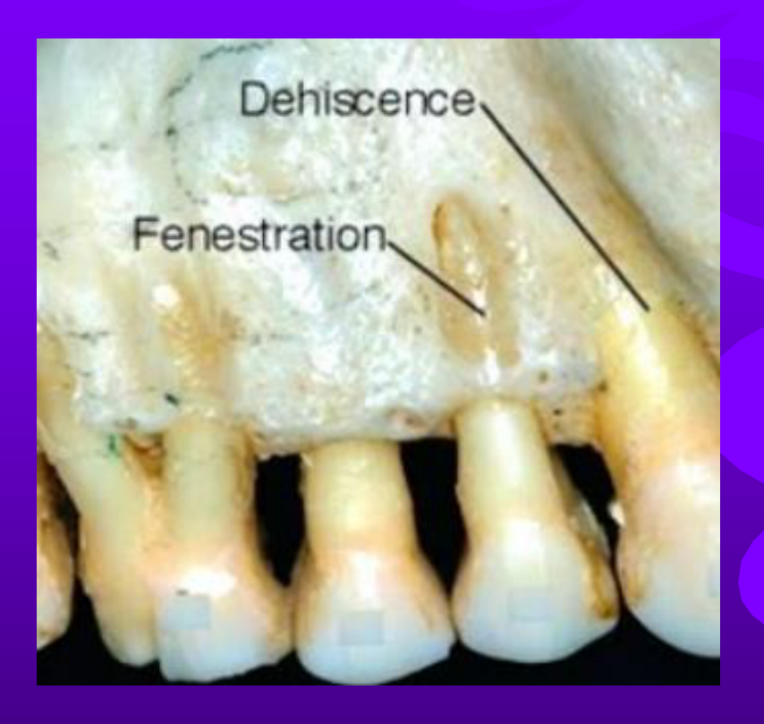
- Buccal/lingual bone not possible to examine on 2D imaging – buccal bone deficiencies may be present in health (dehiscences/fenestrations).
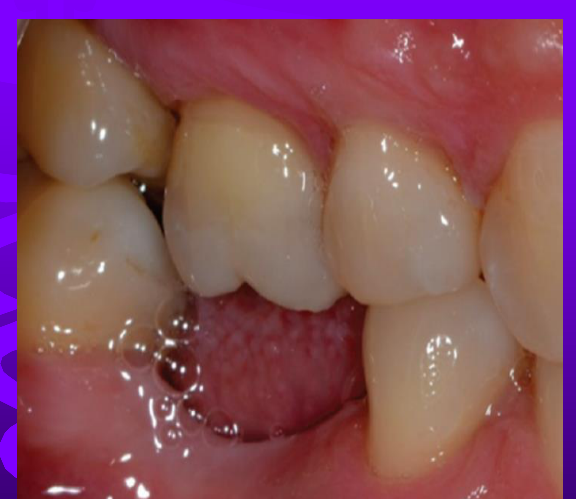
- If teeth have supraerupted, distance between CEJ and crestal bone is more.
 |  |
 |  |
Assessment Of Bone Destruction32
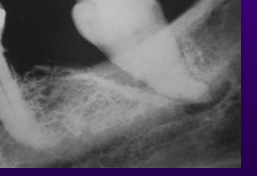
Interpreting bone destruction in periodontal disease
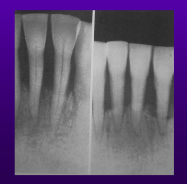
Periodontal bone loss starts at the alveolar crest.
Initial phase, reduced density of cortical bone.
Slight radiographic changes in bone height means progression to early stages of periodontitis.
- Hence the earliest signs are easier to detect clinically by probing.
- X-ray underestimates bone loss compared with clinical assessment.
- Average distance from CEJ to interproximal alveolar crest is 1.5 to 2 mm hence bone loss is determined by measuring the distance from the crest to the CEJ.
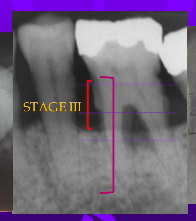
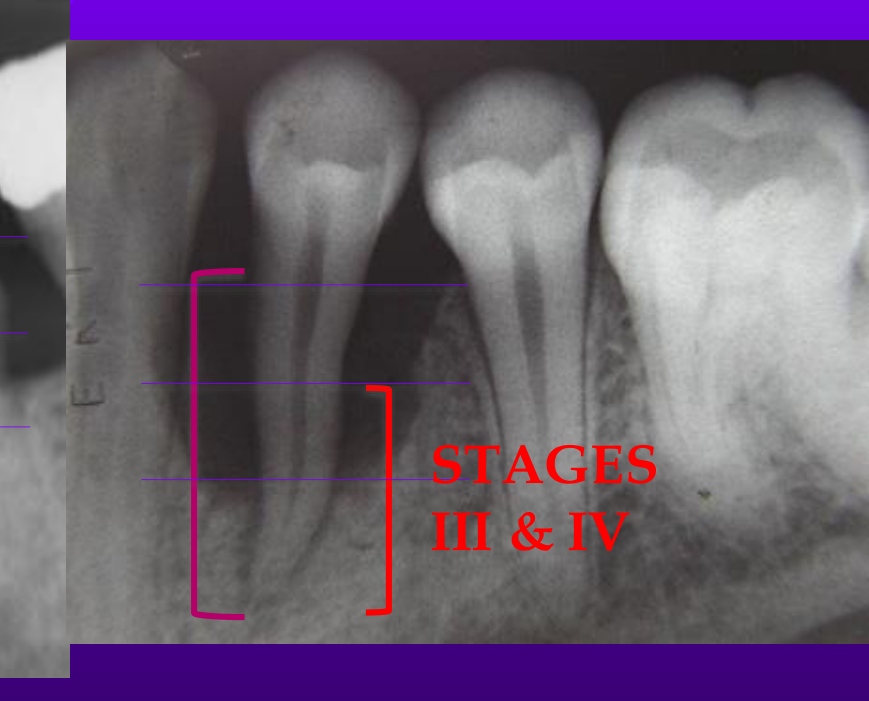
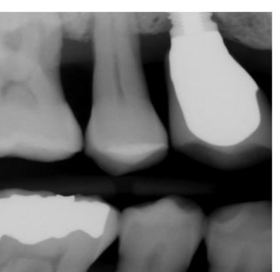
Severity And Classification Stages333435363738
Severity and the Classification Stages
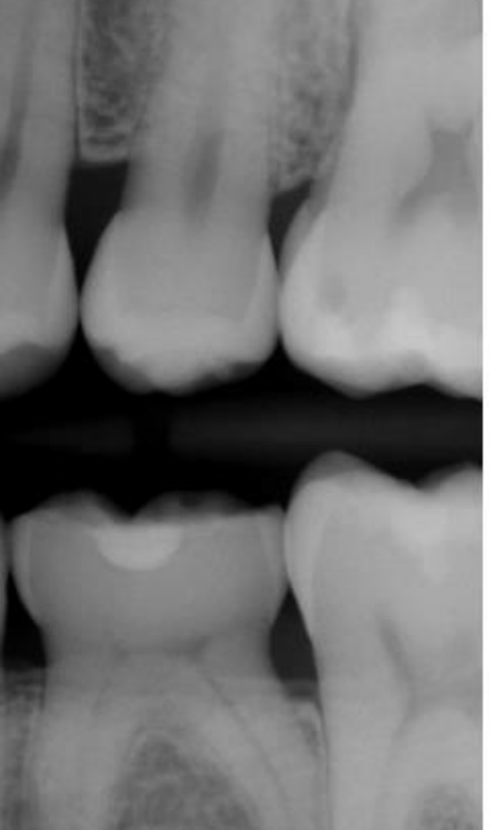
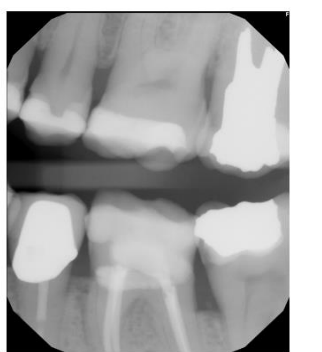
- Mild - stage I (less than 15%)
- Moderate - stage II (15-33%)
- Stage III and Stage IV (extends to mid 1/3 and beyond)
- Advanced bone loss - stage III - IV
- % of bone loss and root length
Severity and the Radiographic Report in Your Perio Eform
- Mild - less than 33% bone loss
- Moderate – between 33 and 66%
- Severe - more than 66%
- Pattern - horizontal / vertical
- Distribution - localized or generalized.
Stage 2 Periodontal Disease (mandibular + maxillary left posterior) bitewing radiograph: Radiographic bone loss limited to the coronal third (15%-33%). Image provided by authors.
 |  |  |
 |  |  |
Peri Implant Conditions39404142
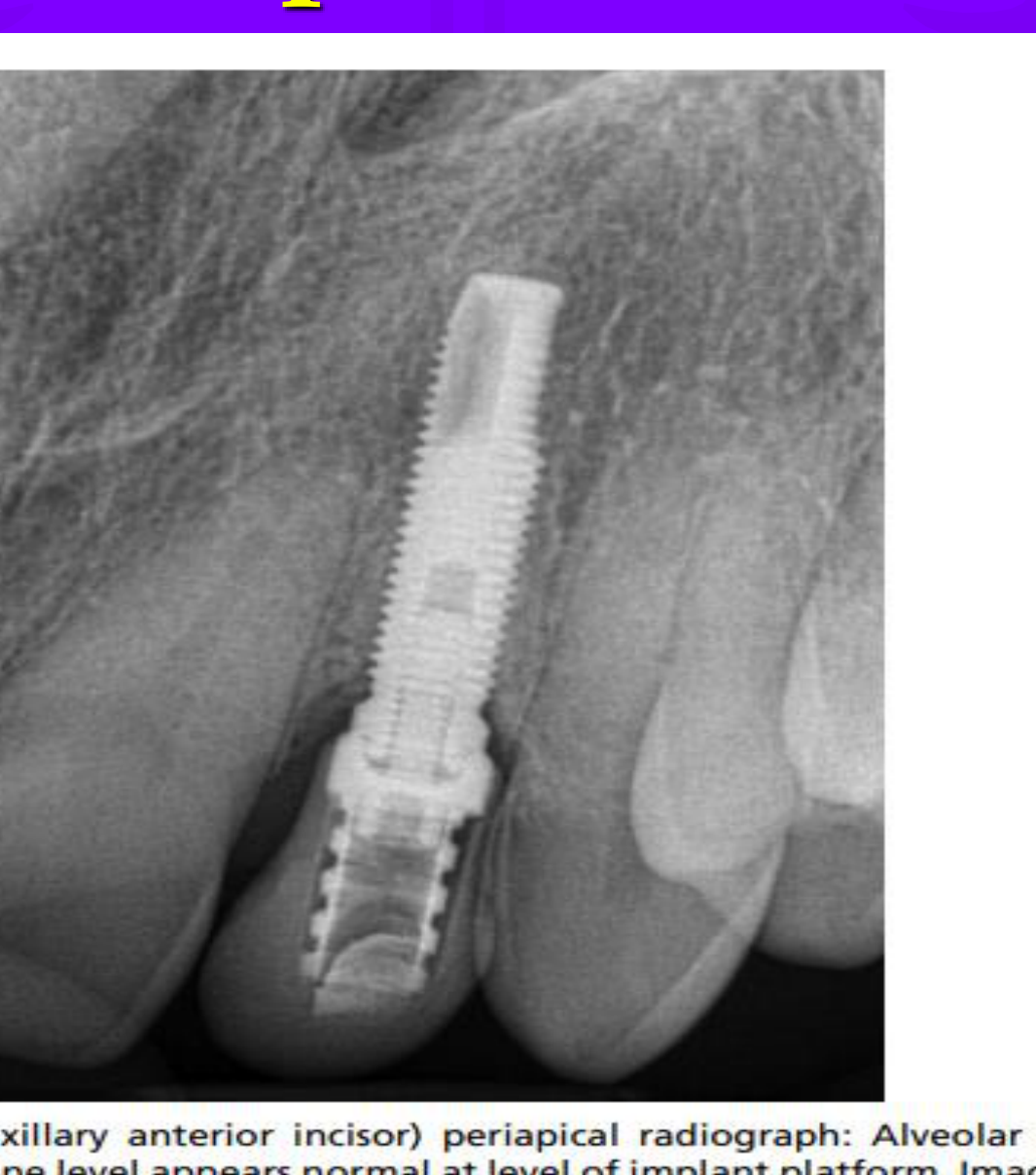
Normal implant bone levels
Fig. 23 Mucositis (maxillary anterior incisor) periapical radiograph: Alveolar crest levels appear radiopaque. Bone level appears normal at level of implant platform. Image provided by authors.
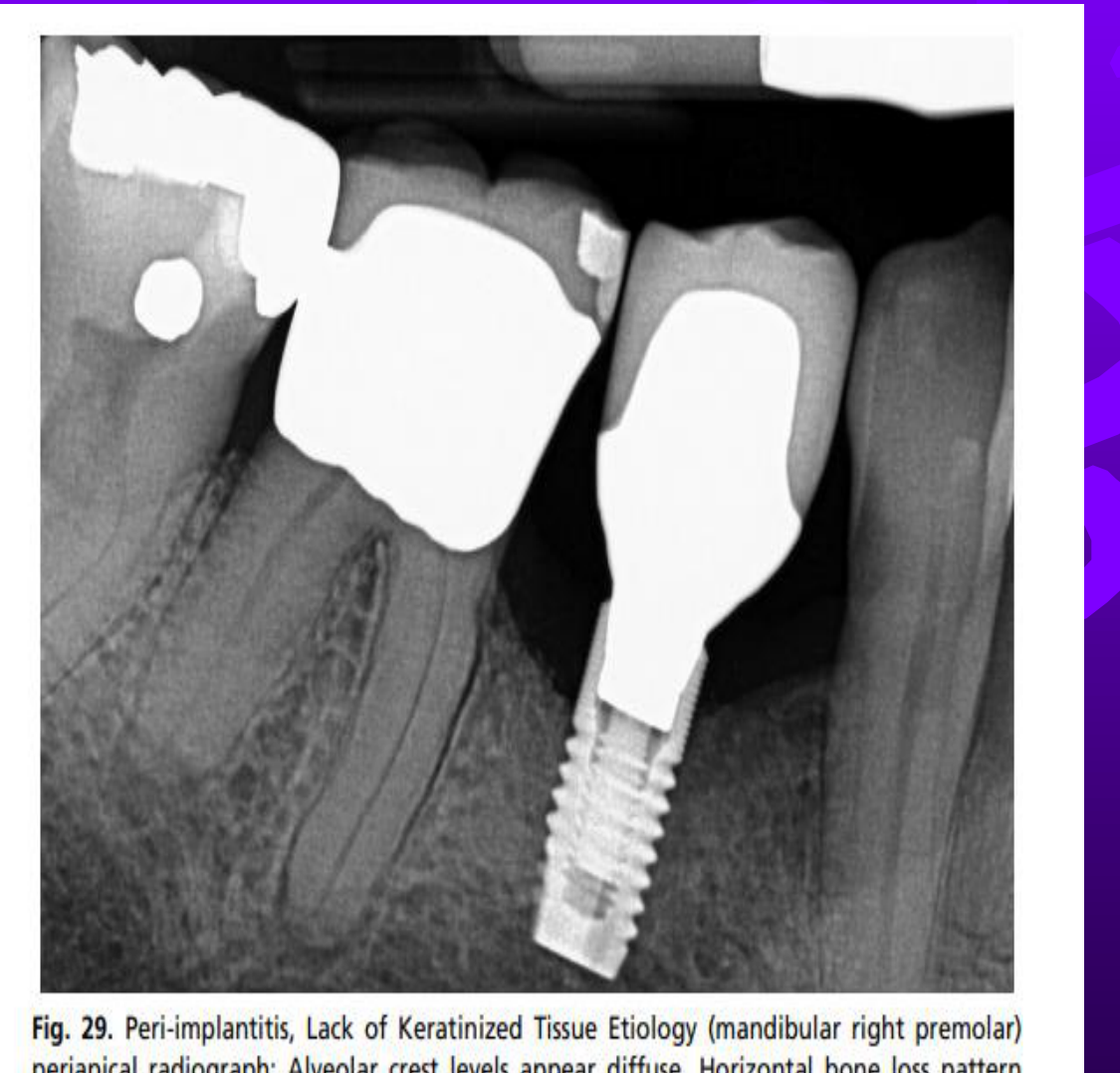
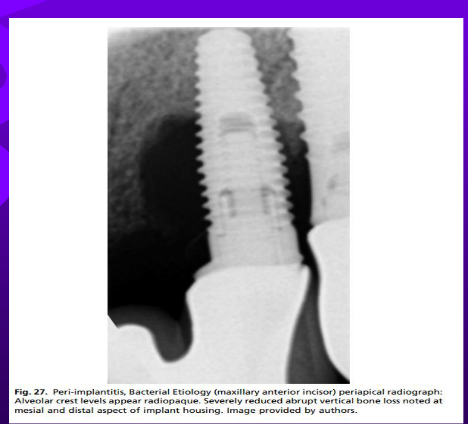
Peri-implantitis
Fig. 29. Peri-implantitis, Lack of Keratinized Tissue Etiology (mandibular right premolar) periapical radiograph: Alveolar crest levels appear diffuse. Horizontal bone loss pattern noted. Image provided by authors.
Fig. 27. Peri-implantitis, Bacterial Etiology (maxillary anterior incisor) periapical radiograph: Alveolar crest levels appear radiopaque. Severely reduced abrupt vertical bone loss noted at mesial and distal aspect of implant housing. Image provided by authors.
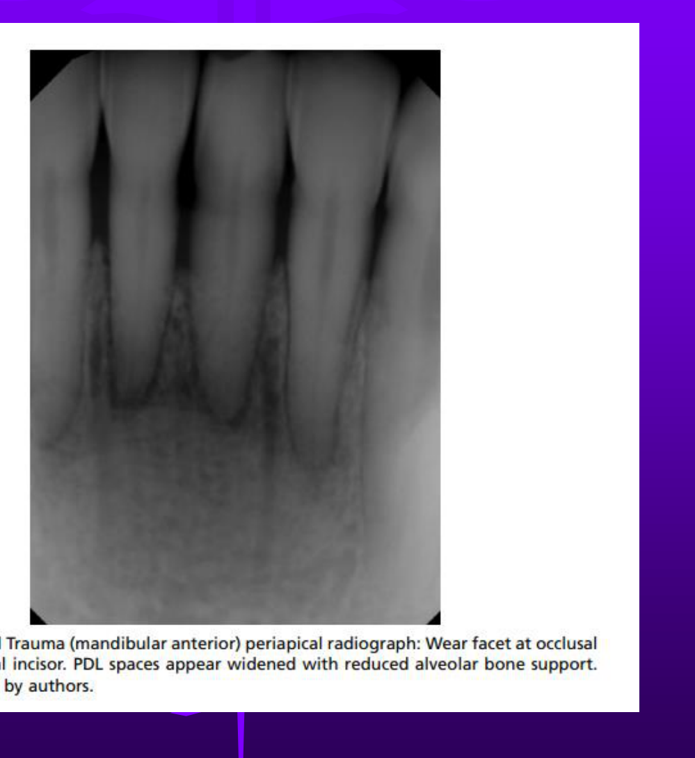
Occlusal trauma - widened PDL space, thickened lamina dura
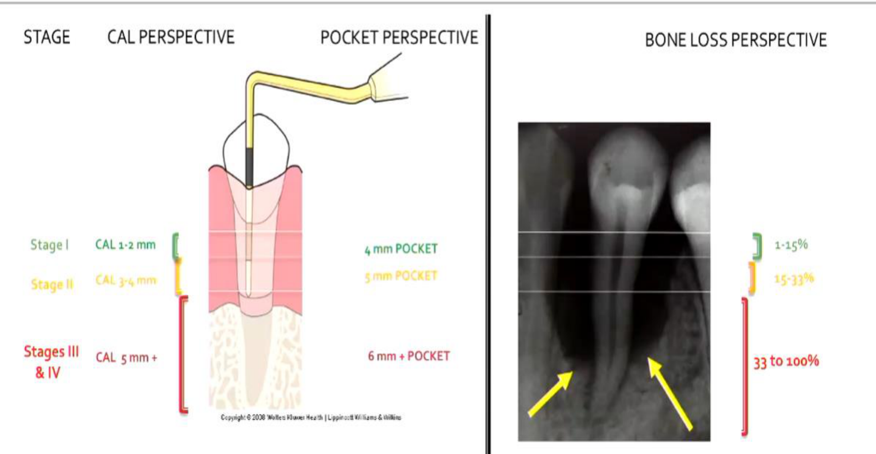
| STAGE | CAL PERSPECTIVE | POCKET PERSPECTIVE | BONE LOSS PERSPECTIVE |
|---|---|---|---|
| Stage I | CAL 1-2 mm | 4 mm POCKET | 1-15% |
| Stage II | CAL 3-4 mm | 5 mm POCKET | 15-33% |
| Stages III & IV | CAL 5 mm + | 6 mm + POCKET | 33 to 100% |
Copyright © 2008 Wolters Kluwer Health | Lippincott Williams & Wilkins
 |  |  |
 |  |
Morphology And Pattern Of Bone Loss4344
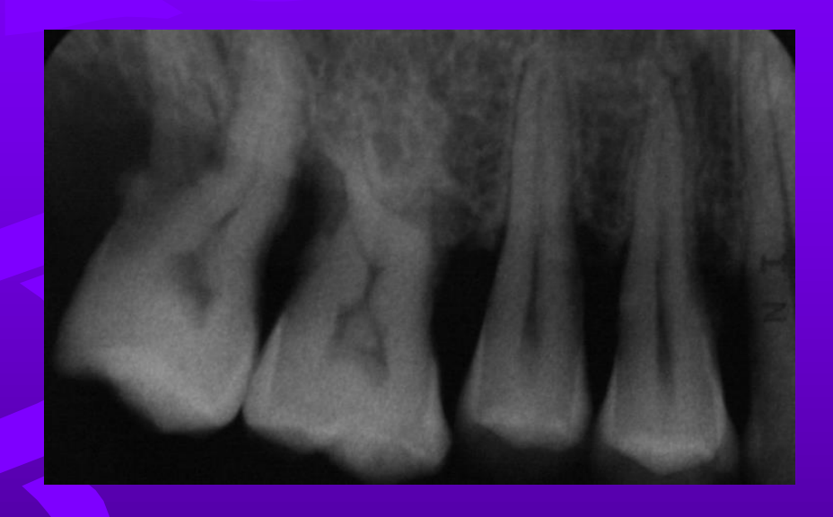
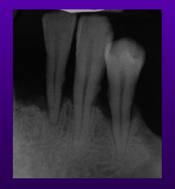
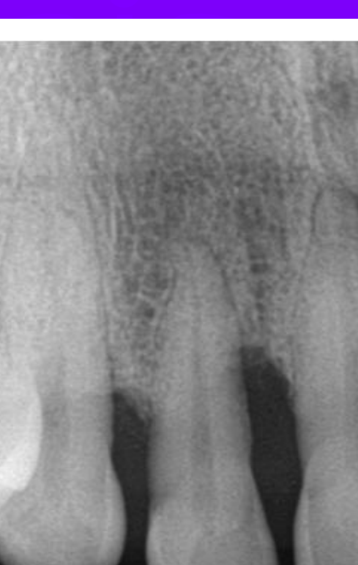
Radiographic Interpretation - Morphology of Bone Loss
- Bone loss type
- Horizontal bone loss
- Vertical bone loss
Assessing bone loss more difficult on 2D images.
 |  |
 |
Intrabony And Crater Defects4546474849
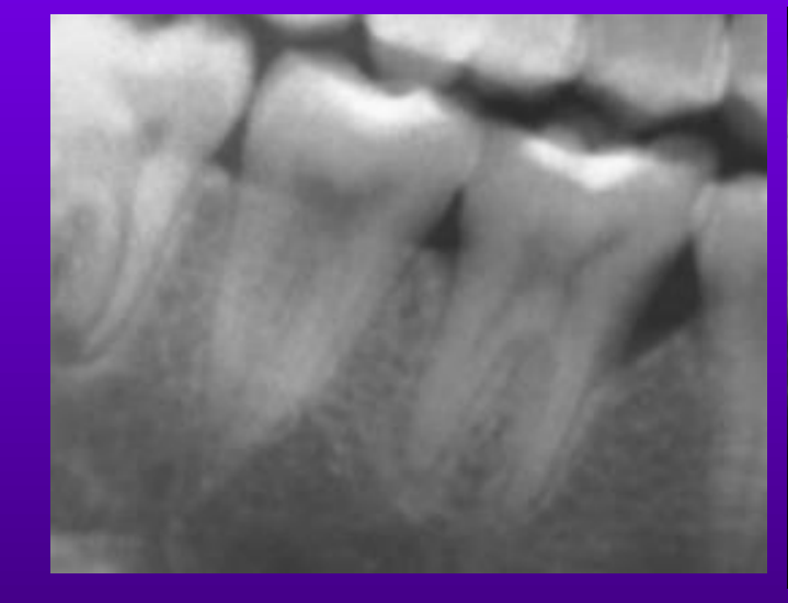
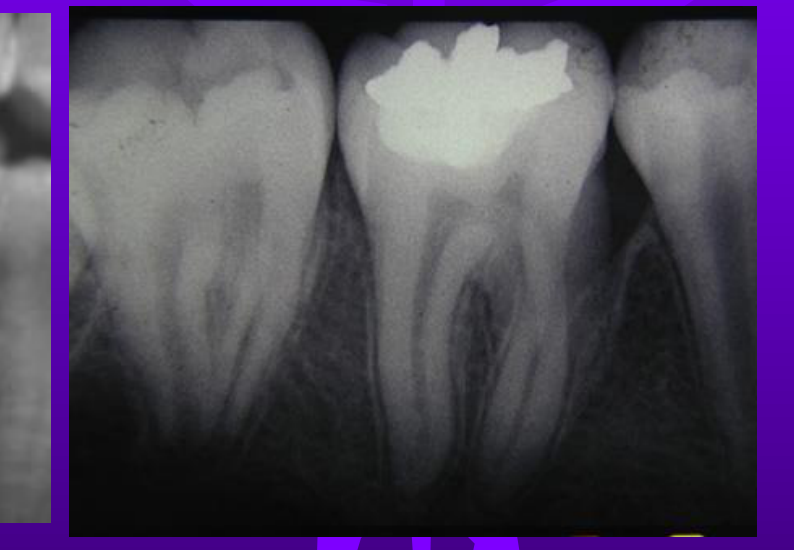
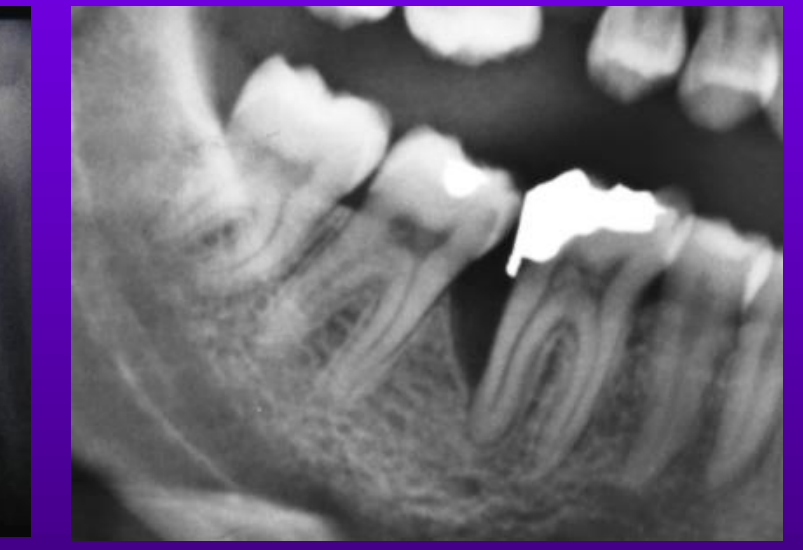
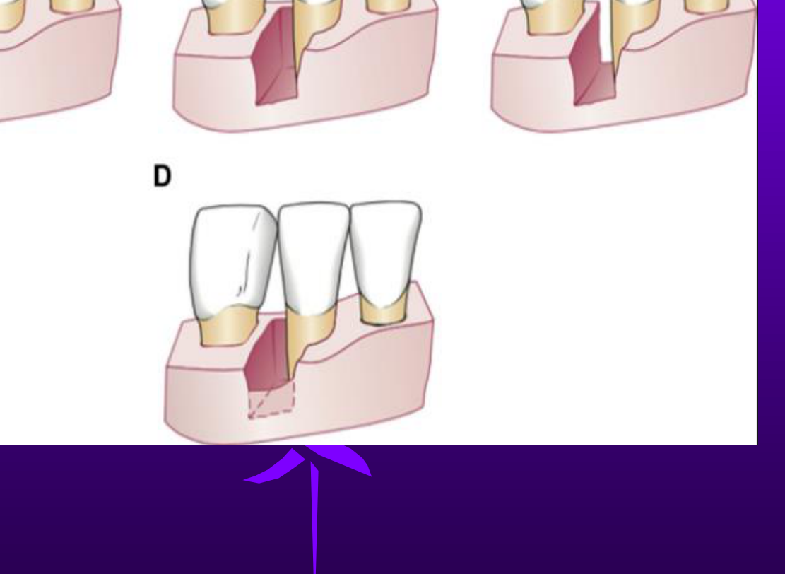
Vertical/angular/intrabony/infrabony/crater bone defects - different types
Pattern of Intrabony Defects; 1, 2, 3 Walled Defects
Number of Remaining Walls
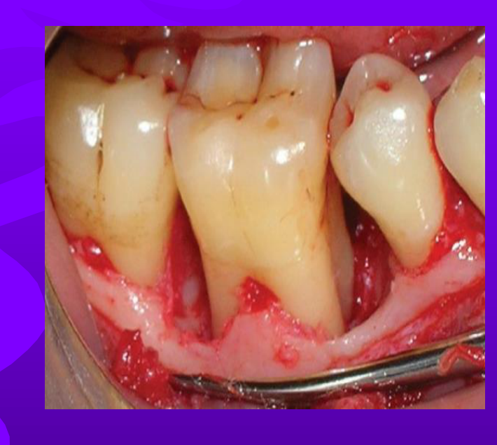
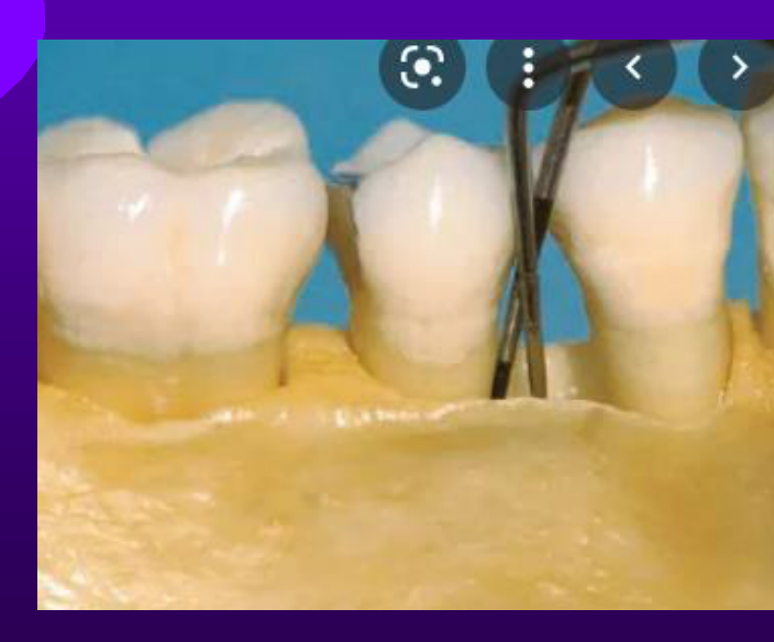
Crater Defects
Buccal and lingual plate higher than the base of a defect - difficult to detect on 2D imaging - may appear as more radiolucent except if B/L bone very thick.
Images of teeth showing crater defects, one intraoperative and one on a dental model.
Radiopaque Horizontal Line for Labial or Lingual Bone Level
Distribution
- Localised less than 30%
- Generalised more than 30%
 |  |  |
 |  |  |
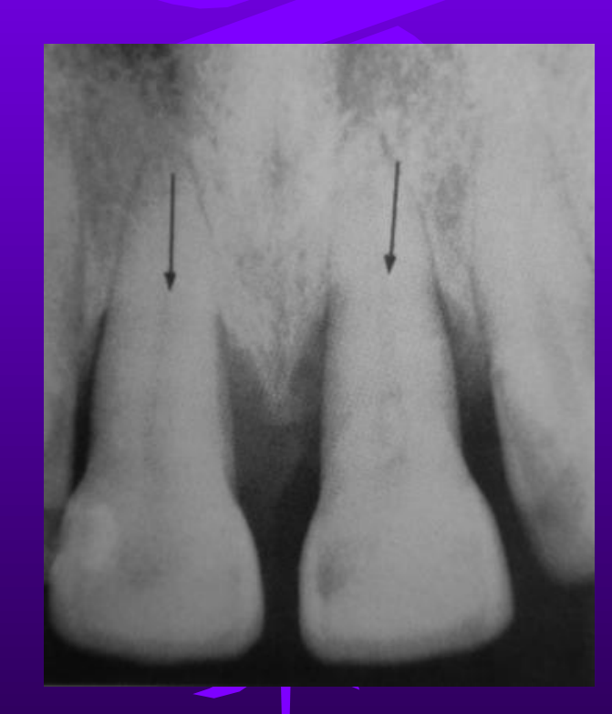 |
Furcation Involvement505152
Furcation Defects
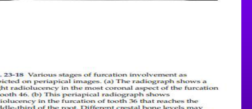
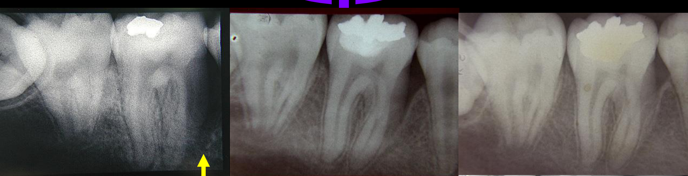
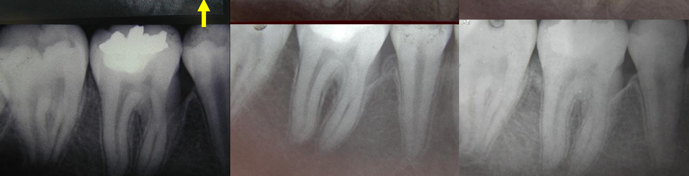
- In multirooted teeth, hard to see bone loss in furcations on 2D images because of superimpositioning of bone and roots.
- Variations in radiolucency may help detect bone loss.
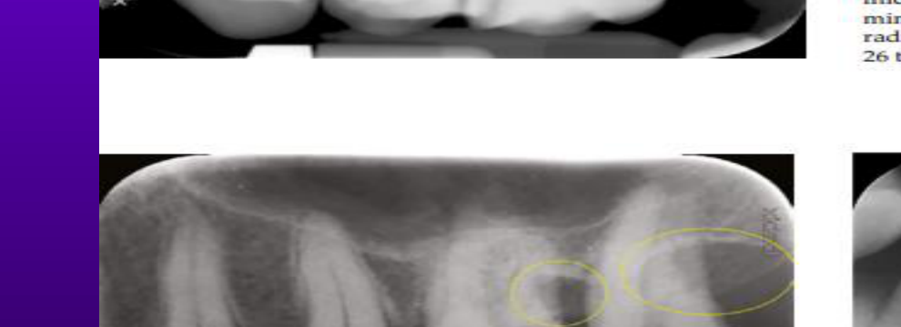
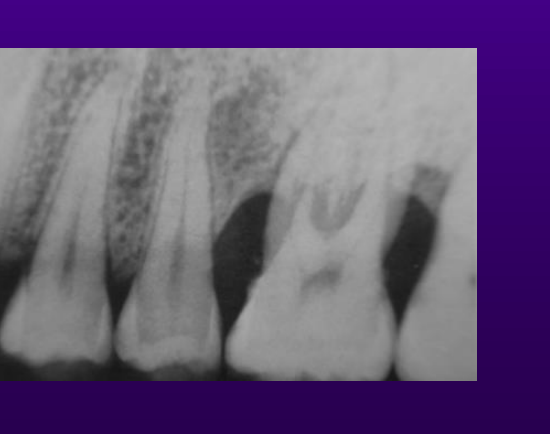
- Inverted J shape on maxillary molars - sign of distal furcation bone loss.
- Unless the radiograph is standardised and reproducible, very hard to compare before and after treatment/deterioration.
- CBCT more accurate as a diagnostic tool but not recommended for follow-up and monitoring.
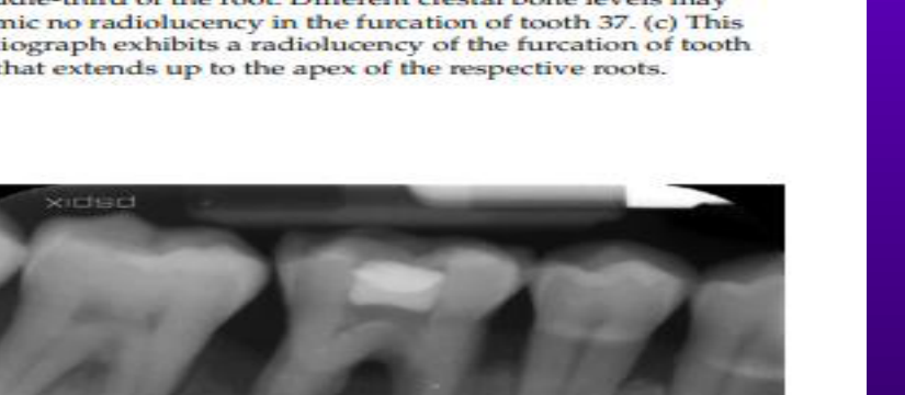
Interpretation of Furcation Defects in 2D Imaging
Fig. 23-18 Various stages of furcation involvement as depicted on periapical images. (a) The radiograph shows a slight radiolucency in the most coronal aspect of the furcation of tooth 46. (b) This periapical radiograph shows radiolucency in the furcation of tooth 36 that reaches the middle-third of the root. Different crestal bone levels may mimic no radiolucency in the furcation of tooth 37. (c) This radiograph exhibits a radiolucency of the furcation of tooth 26 that extends up to the apex of the respective roots.
Fig. 23-19 A periapical image demonstrating a radiolucent triangle superimposed over the distal roots of tooth 26 and demonstrating the hooks of the “J” shaped radiolucency on the distal root of tooth 27, both of which indicate bone destruction extending into the furcation of the respective regions (yellow circles).
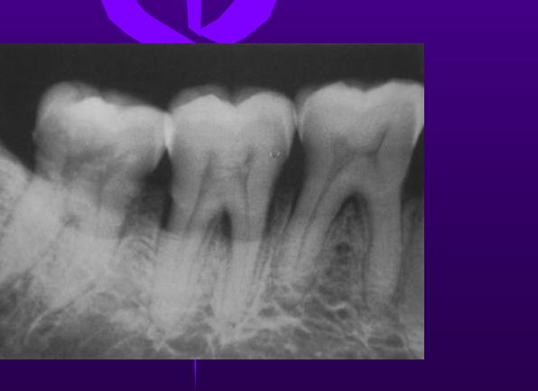
Fig. 23-20 This periapical image shows an extended radiolucency from the alveolar crest to the periapical region of tooth 46. This points towards the presence of periodontal and periapical inflammatory pathologies (perio-endo lesion).
Periodontitis Radiographic Appearance
- Depends on radiographic technique, tube angulation and film placement.
- Also depends on anatomical variations thickness and density of interdental bone, position of teeth.
- Presence of an intact lamina dura indicates health but its absence doesn’t mean disease.
- Furcations may appear as a wedge shaped radiolucent area mesial and or distal with apex pointing to the crown.
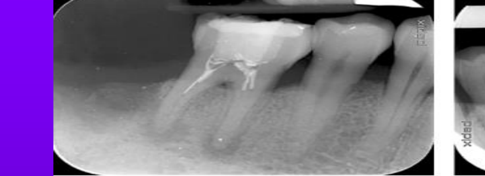 | 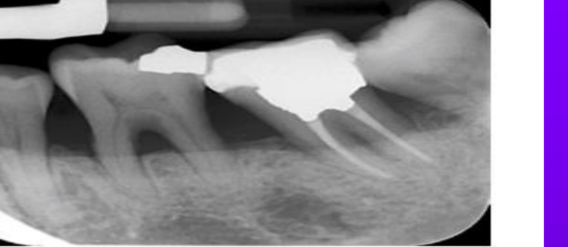 | 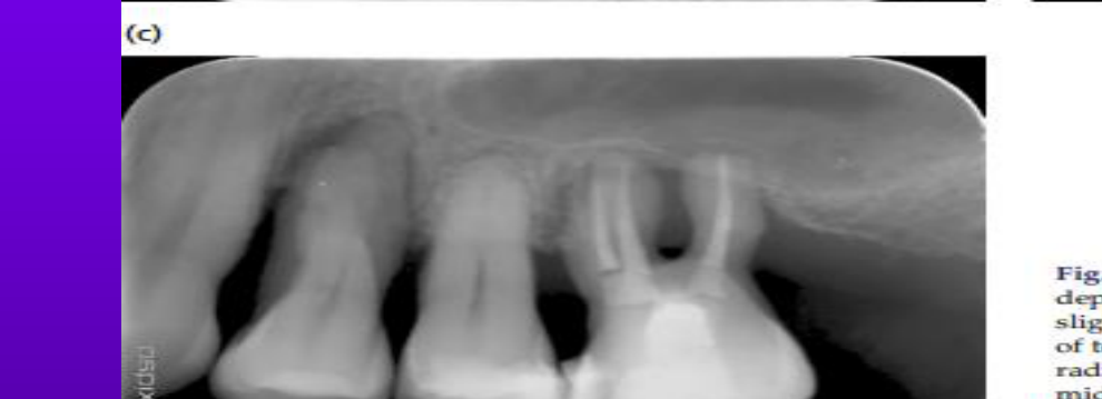 |
 |  |  |
 |  |
Systemic Manifestations And Healing535455
Healing After Treatment
Some Systemic conditions can present with periodontal manifestations radiographically
- OSTEITIS FIBROSA
- PAGET’S DISEASE
- FIBROUS DYSPLASIA
- HISTIOCYTOSIS
- OSTEOPETROSIS
- SCLERODERMA
- MALIGNANCY
- CARCINOMA OF THE JAW
- OSTEOSARCOMA
Distribution
 |  |
 | 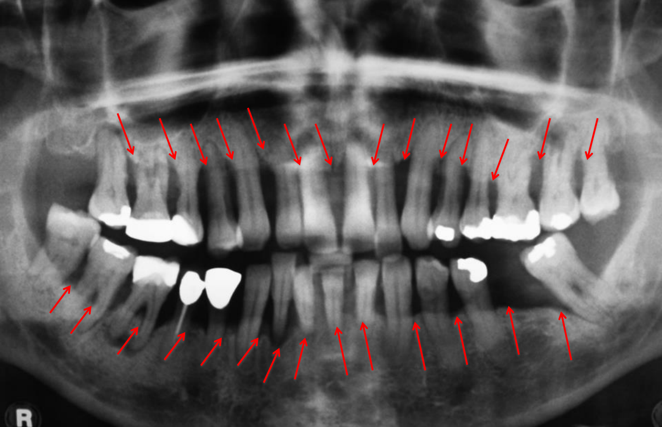 |
Clinical Recommendations And Conclusion
Recommendations for Periodontal disease assessment56
- OPG is sufficient for an overview – occasionally and alternatively full-mouth periapicals can be used.
- Additional intraoral views can be used for more detail on bone levels and root morphology – however limited detail on furcation and intrabony defects.
- CBCT/MDCT provides a lot more detail if accuracy is important in evaluation of prognosis and treatment planning – but not recommended for follow-up examinations.
When is volumetric analysis useful in perio57
- To determine the extent and pattern of periodontal bone loss, including infrabony defects, dehiscences, fenestrations
- Furcation morphology i.e. width of entrance, pattern of bone loss in furcations
- Root morphology
- Root fractures
- Periapical status
- Origin of infection
- Pre-surgical / implant planning
- Pre-ortho in thin phenotypes / perio patients
To conclude58
- Justification – Prescribe radiological exam only if clinical exam does not provide sufficient diagnostic information
- Optimization – Follow the lowest dose protocol to achieve the diagnosis
Keep updated in theories and techniques of radiological assessment.
References59
- THANK YOU!
RECOMMENDED READING
Lindhe’s Clinical Periodontology and Implant Dentistry 7th edition Chapter 23.
Periodontal and Implant Radiology
Joseph P. Fiorellini, DMD, DMSc^a,^b^*, Dennis Sourvanos, BBDH, DDS^a,^b, Hector Sarimento, DMD, MSOB^a,^b, Nadeem Karimbux, DMD, MMSc^a,^b, Kevin W. Luan, BDS, MSOB, MEd^a,^b^c^
Dent Clin N Am 65 (2021) 447–473
https://doi.org/10.1016/j.cden.2021.02.003
0011-8532/21/© 2021 Elsevier Inc. All rights reserved.
Footnotes
-
Original PDF page 1: L2RADIOGRAPHY IN PERIODONTOLOGY, p.1 ↩
-
Original PDF page 2: L2RADIOGRAPHY IN PERIODONTOLOGY, p.2 ↩
-
Original PDF page 3: L2RADIOGRAPHY IN PERIODONTOLOGY, p.3 ↩
-
Original PDF page 4: L2RADIOGRAPHY IN PERIODONTOLOGY, p.4 ↩
-
Original PDF page 5: L2RADIOGRAPHY IN PERIODONTOLOGY, p.5 ↩
-
Original PDF page 6: L2RADIOGRAPHY IN PERIODONTOLOGY, p.6 ↩
-
Original PDF page 7: L2RADIOGRAPHY IN PERIODONTOLOGY, p.7 ↩
-
Original PDF page 8: L2RADIOGRAPHY IN PERIODONTOLOGY, p.8 ↩
-
Original PDF page 9: L2RADIOGRAPHY IN PERIODONTOLOGY, p.9 ↩
-
Original PDF page 10: L2RADIOGRAPHY IN PERIODONTOLOGY, p.10 ↩
-
Original PDF page 11: L2RADIOGRAPHY IN PERIODONTOLOGY, p.11 ↩
-
Original PDF page 12: L2RADIOGRAPHY IN PERIODONTOLOGY, p.12 ↩
-
Original PDF page 13: L2RADIOGRAPHY IN PERIODONTOLOGY, p.13 ↩
-
Original PDF page 15: L2RADIOGRAPHY IN PERIODONTOLOGY, p.15 ↩
-
Original PDF page 16: L2RADIOGRAPHY IN PERIODONTOLOGY, p.16 ↩
-
Original PDF page 18: L2RADIOGRAPHY IN PERIODONTOLOGY, p.18 ↩
-
Original PDF page 21: L2RADIOGRAPHY IN PERIODONTOLOGY, p.21 ↩
-
Original PDF page 22: L2RADIOGRAPHY IN PERIODONTOLOGY, p.22 ↩
-
Original PDF page 23: L2RADIOGRAPHY IN PERIODONTOLOGY, p.23 ↩
-
Original PDF page 24: L2RADIOGRAPHY IN PERIODONTOLOGY, p.24 ↩
-
Original PDF page 25: L2RADIOGRAPHY IN PERIODONTOLOGY, p.25 ↩
-
Original PDF page 26: L2RADIOGRAPHY IN PERIODONTOLOGY, p.26 ↩
-
Original PDF page 27: L2RADIOGRAPHY IN PERIODONTOLOGY, p.27 ↩
-
Original PDF page 28: L2RADIOGRAPHY IN PERIODONTOLOGY, p.28 ↩
-
Original PDF page 29: L2RADIOGRAPHY IN PERIODONTOLOGY, p.29 ↩
-
Original PDF page 30: L2RADIOGRAPHY IN PERIODONTOLOGY, p.30 ↩
-
Original PDF page 31: L2RADIOGRAPHY IN PERIODONTOLOGY, p.31 ↩
-
Original PDF page 32: L2RADIOGRAPHY IN PERIODONTOLOGY, p.32 ↩
-
Original PDF page 33: L2RADIOGRAPHY IN PERIODONTOLOGY, p.33 ↩
-
Original PDF page 34: L2RADIOGRAPHY IN PERIODONTOLOGY, p.34 ↩
-
Original PDF page 35: L2RADIOGRAPHY IN PERIODONTOLOGY, p.35 ↩
-
Original PDF page 36: L2RADIOGRAPHY IN PERIODONTOLOGY, p.36 ↩
-
Original PDF page 37: L2RADIOGRAPHY IN PERIODONTOLOGY, p.37 ↩
-
Original PDF page 38: L2RADIOGRAPHY IN PERIODONTOLOGY, p.38 ↩
-
Original PDF page 39: L2RADIOGRAPHY IN PERIODONTOLOGY, p.39 ↩
-
Original PDF page 40: L2RADIOGRAPHY IN PERIODONTOLOGY, p.40 ↩
-
Original PDF page 45: L2RADIOGRAPHY IN PERIODONTOLOGY, p.45 ↩
-
Original PDF page 46: L2RADIOGRAPHY IN PERIODONTOLOGY, p.46 ↩
-
Original PDF page 41: L2RADIOGRAPHY IN PERIODONTOLOGY, p.41 ↩
-
Original PDF page 42: L2RADIOGRAPHY IN PERIODONTOLOGY, p.42 ↩
-
Original PDF page 43: L2RADIOGRAPHY IN PERIODONTOLOGY, p.43 ↩
-
Original PDF page 44: L2RADIOGRAPHY IN PERIODONTOLOGY, p.44 ↩
-
Original PDF page 47: L2RADIOGRAPHY IN PERIODONTOLOGY, p.47 ↩
-
Original PDF page 48: L2RADIOGRAPHY IN PERIODONTOLOGY, p.48 ↩
-
Original PDF page 49: L2RADIOGRAPHY IN PERIODONTOLOGY, p.49 ↩
-
Original PDF page 50: L2RADIOGRAPHY IN PERIODONTOLOGY, p.50 ↩
-
Original PDF page 51: L2RADIOGRAPHY IN PERIODONTOLOGY, p.51 ↩
-
Original PDF page 52: L2RADIOGRAPHY IN PERIODONTOLOGY, p.52 ↩
-
Original PDF page 53: L2RADIOGRAPHY IN PERIODONTOLOGY, p.53 ↩
-
Original PDF page 54: L2RADIOGRAPHY IN PERIODONTOLOGY, p.54 ↩
-
Original PDF page 55: L2RADIOGRAPHY IN PERIODONTOLOGY, p.55 ↩
-
Original PDF page 56: L2RADIOGRAPHY IN PERIODONTOLOGY, p.56 ↩
-
Original PDF page 57: L2RADIOGRAPHY IN PERIODONTOLOGY, p.57 ↩
-
Original PDF page 58: L2RADIOGRAPHY IN PERIODONTOLOGY, p.58 ↩
-
Original PDF page 59: L2RADIOGRAPHY IN PERIODONTOLOGY, p.59 ↩
-
Original PDF page 60: L2RADIOGRAPHY IN PERIODONTOLOGY, p.60 ↩
-
Original PDF page 61: L2RADIOGRAPHY IN PERIODONTOLOGY, p.61 ↩
-
Original PDF page 62: L2RADIOGRAPHY IN PERIODONTOLOGY, p.62 ↩
-
Original PDF page 63: L2RADIOGRAPHY IN PERIODONTOLOGY, p.63 ↩