Radiation Physics and Safety12
Dr Dayea Oh
Oral and Maxillofacial Radiologist
UWA Dental School
Recommended Textbooks
-
Essentials of dental radiography and radiology 5th edition by Whaites, Eric; Drage, Nicholas Churchill Livingstone 2013
-
Pocket atlas of dental radiology by Pasler, Friedrich A; Visser, Heiko Flexibook, 2007
-
Oral radiology: principles and interpretation 7th edition by White, Stuart C; Pharoah, M. J Permalink 2014
- 8th edition available now
Radiation Physics34
- Radiation Physics
How is x-ray generated?
- X-ray Use in Dentistry
- What is X-ray?
- Ionising radiation
- How is X-ray generated?
- Spectrum of X-ray Photons
- Bremsstrahlung & Characteristic Radiations
- Factors Controlling the X-ray Beam
History and Clinical Indications56
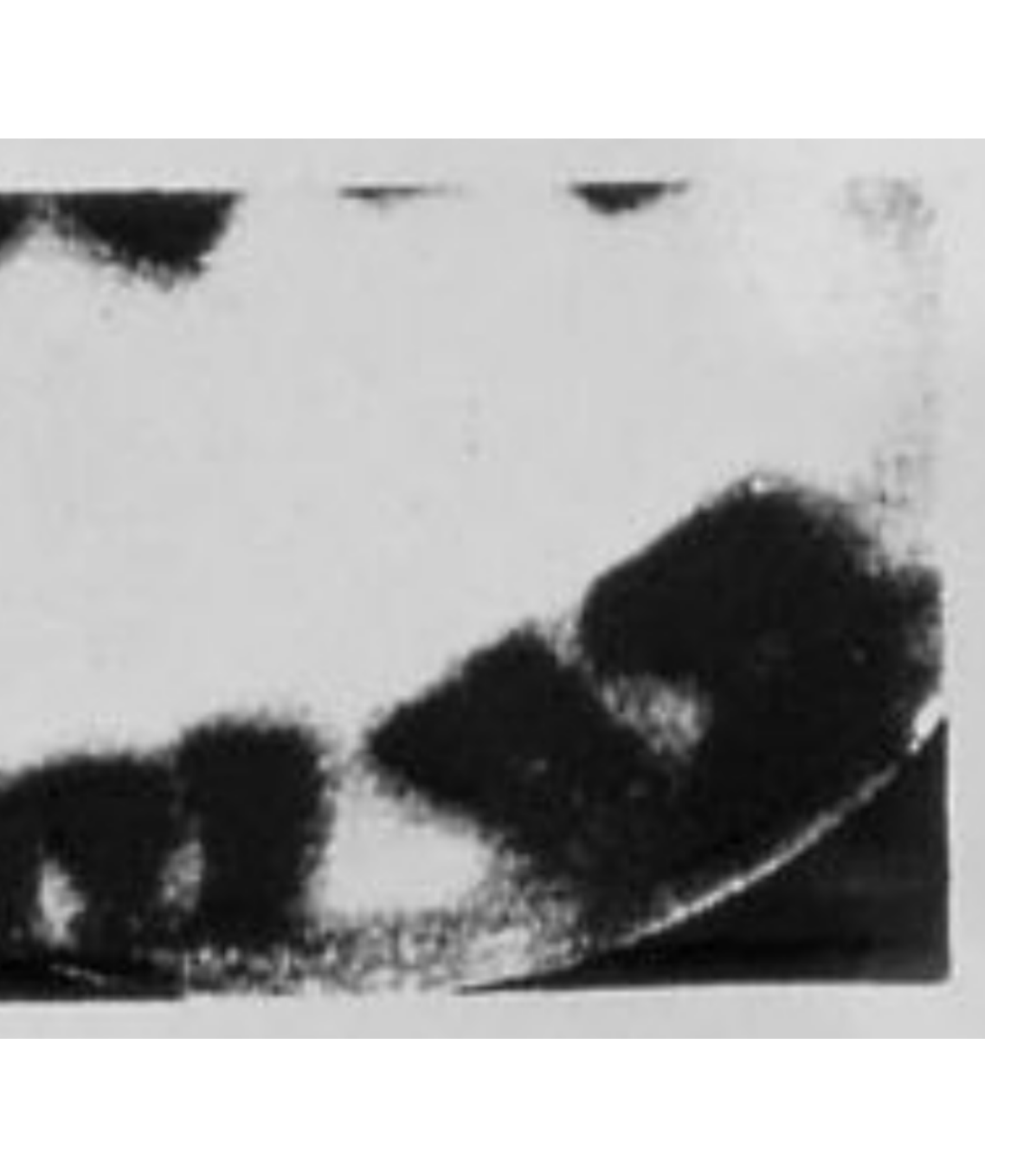
History of Dental X-ray
Professor Wilhelm Conrad Roentgen discovered the X-ray in 1895
Otto Walkhoff took first dental X-rays on himself (took 25 minutes)
“It was a real torture but I felt tremendously happy when I saw the results. It was when I weighed up the importance of Roentgen’s discovery for future dentistry.”
Indications for Dental X-rays
- Dental History
- Previous treatment
- Clinical Signs and Symptoms
- Dental Pain
- Trauma
- Caries
- Periodontal Disease
- Absence of teeth eg. delayed eruption
- Impacted teeth
- Implants, etc…
 |  |
Nature of Radiation7
- Radiation is the transmission of energy through space and matter.
- Occurs as particulate and electromagnetic radiation.
Two Basic Types of Radiation
Particulate Radiation
- Alpha particles
- Beta particles
Electromagnetic Radiation
- Radio waves
- Microwaves
- Infrared waves
- Ultraviolet light
- Gamma radiation
- X-radiation
Electromagnetic Radiation Theories89
1. Quantum Theory:
- Considers electromagnetic radiation as small discrete particles of energy called photons.
- Electron volt (eV) is the unit of energy
- the amount of energy acquired by one electron accelerating through a potential difference of one volt.
2. Wave Theory:
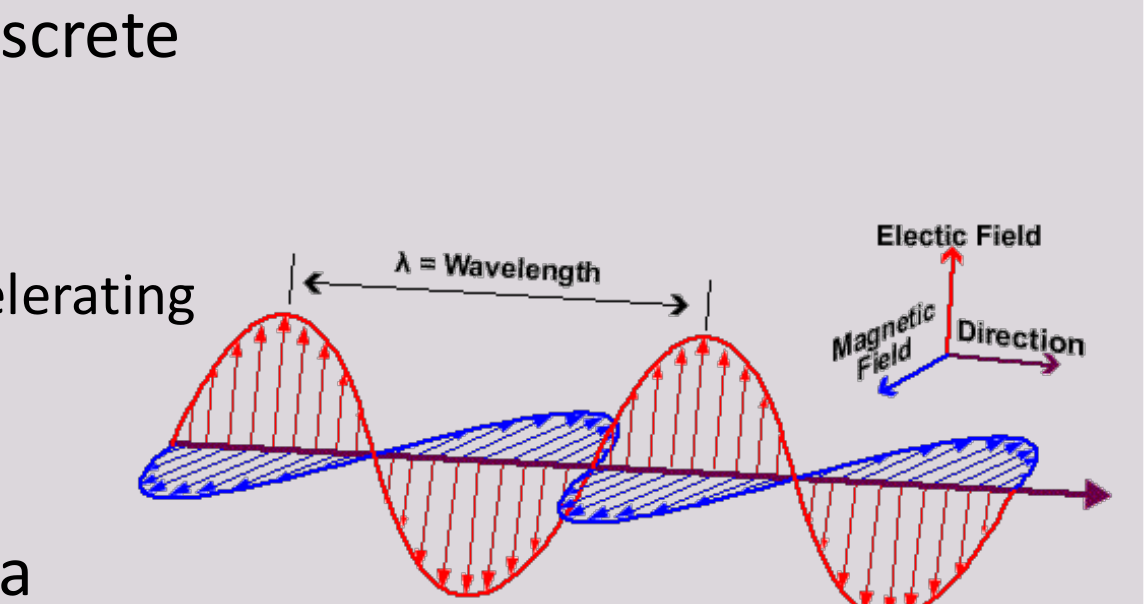
- Movement of photon energy through space as a combination of electric and magnetic fields.
- Fields oriented in planes at right angles to one another that oscillate perpendicular to the direction of motion.
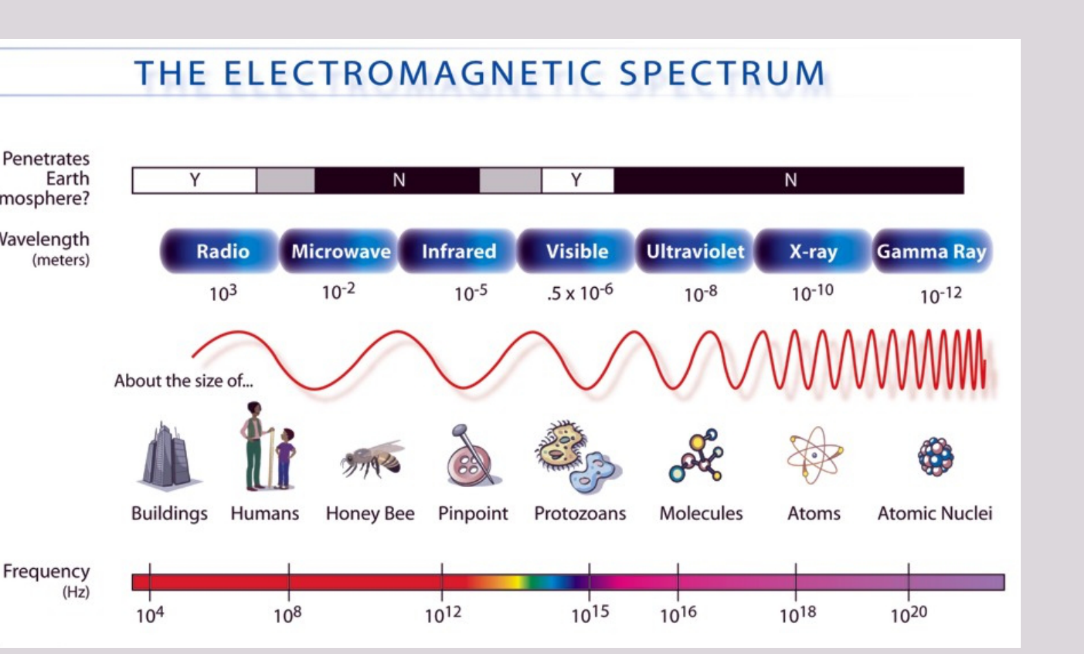
rays, x-rays, UV rays, visible light, infrared radiation (heat), microwaves, and radio waves. All made up of photons.
x-ray photons have high energy and short wavelengths
FIG. Electromagnetic spectrum showing the relationship between wavelength, photon energy, and physical properties of various portions of the spectrum. Note that the photons with shorter wavelengths have higher energy. Photons used in dental radiography have a wavelength of 0.1 to 0.001 nm.
 | 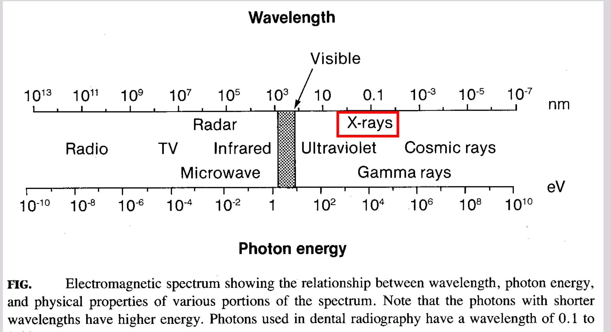 |
The Electromagnetic Spectrum10
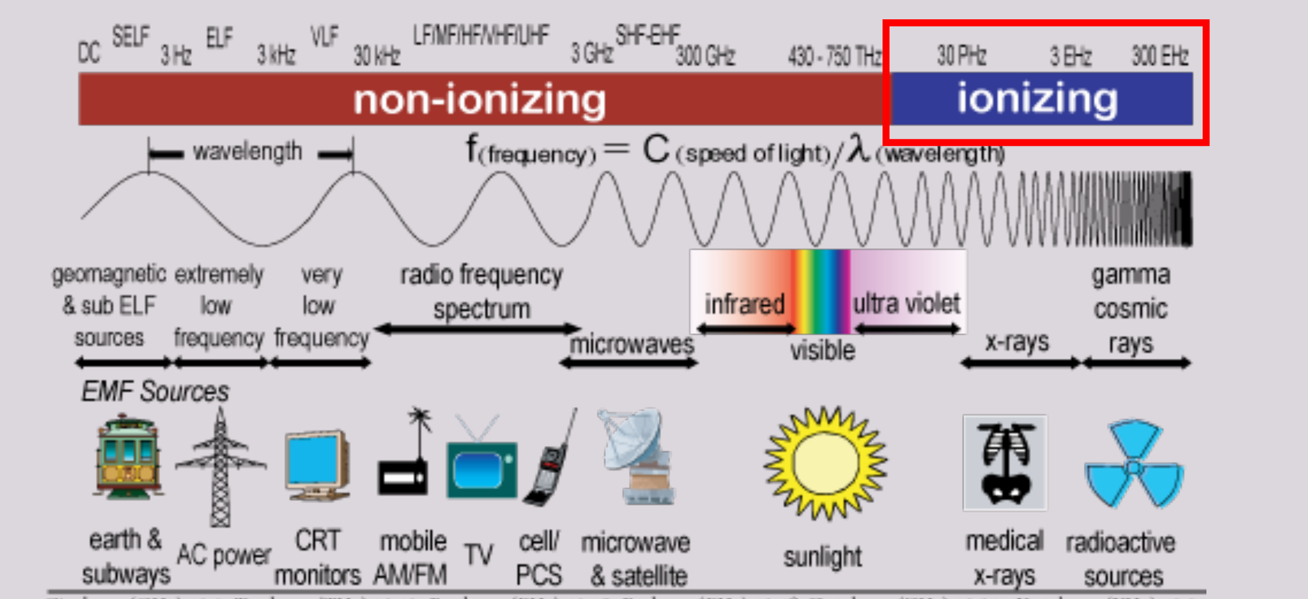
non-ionizing ionizing
wavelength f (frequency) = c (speed of light) / λ (wavelength)
geomagnetic & sub ELF sources extremely low frequency very low frequency radio frequency spectrum microwaves infrared visible ultra violet x-rays gamma cosmic rays
EMF Sources
earth & subways AC power CRT monitors mobile AM/FM TV cell/PCS microwave & satellite sunlight medical x-rays radioactive sources
gigahertz (GHz) 10^-9 terahertz (THz) 10^-12 petahertz (PHz) 10^-15 exahertz (EHz) 10^-18 zettahertz (ZHz) 10^-21 yottahertz (YHz) 10
Properties of X-rays1112
- Composed of photons (a quanta of energy)
- They are invisible
- They have high energy (short wavelengths & high frequencies)
- They have no mass or charge
- Travel at the speed of light
- Each x-ray photon travels in a straight line
- X-ray beam can be deflected and scattered
- Cannot be focused from their point of origin; they diverge
- Can penetrate or may be absorbed by matter (other factors also involved)
- Cause some substances to fluoresce
- Can affect photographic film
- They are ionising radiation & can cause biological damage
 |  |
 |  |
Ionising Radiation and Electron Binding13
Ionising Radiation
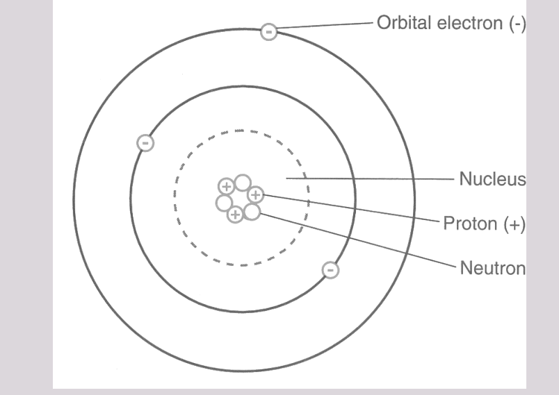
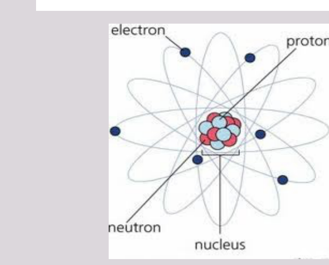
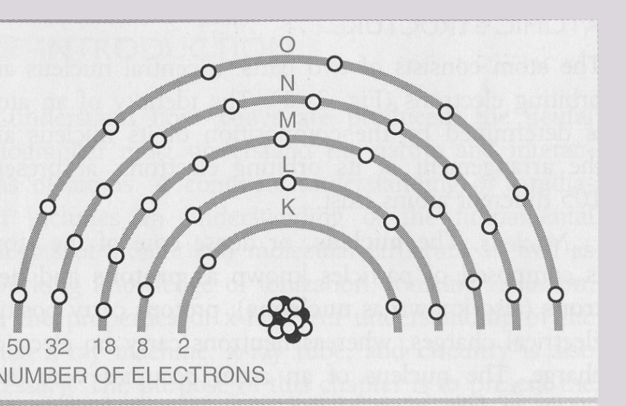
- Ionisation is a process when an atom loses an electron and becomes a positive ion.
- To ionise an atom, sufficient energy is required to overcome the electrostatic force (binding energy of the electrons to the nucleus).
- The binding energy of an electron is related to the atomic number of the atom and the orbital type.
- Large atomic number = large no. of protons in the nucleus → High bind energy of electrons → High energy is required to IONIZE atoms
- For molecules, exposure to ionizing radiation may also break chemical bonds, fragmenting the molecule → biological change!
X-ray Photon Production14
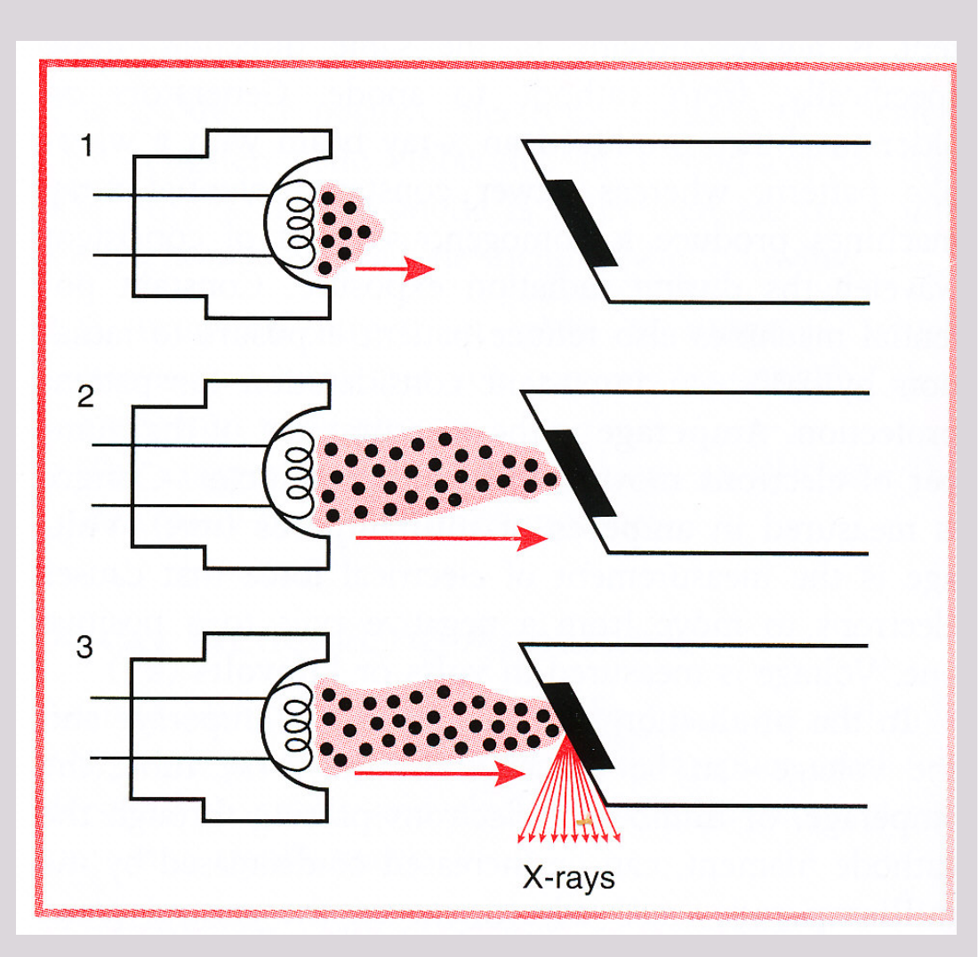
The production of x-ray photons requires 3 important processes:
- Production of electrons
- Acceleration of these electrons such that they have high kinetic energy
- Impact of these electrons into other atoms
Components of the Dental X-ray Tubehead151617
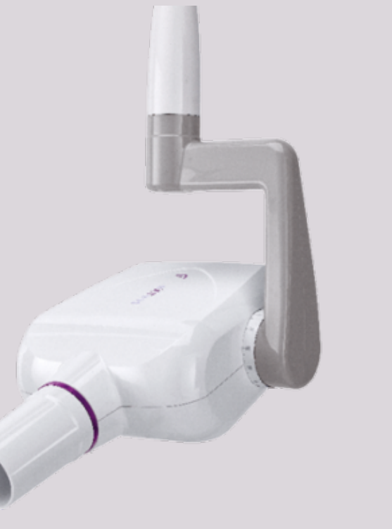
Dental X-ray Tubehead
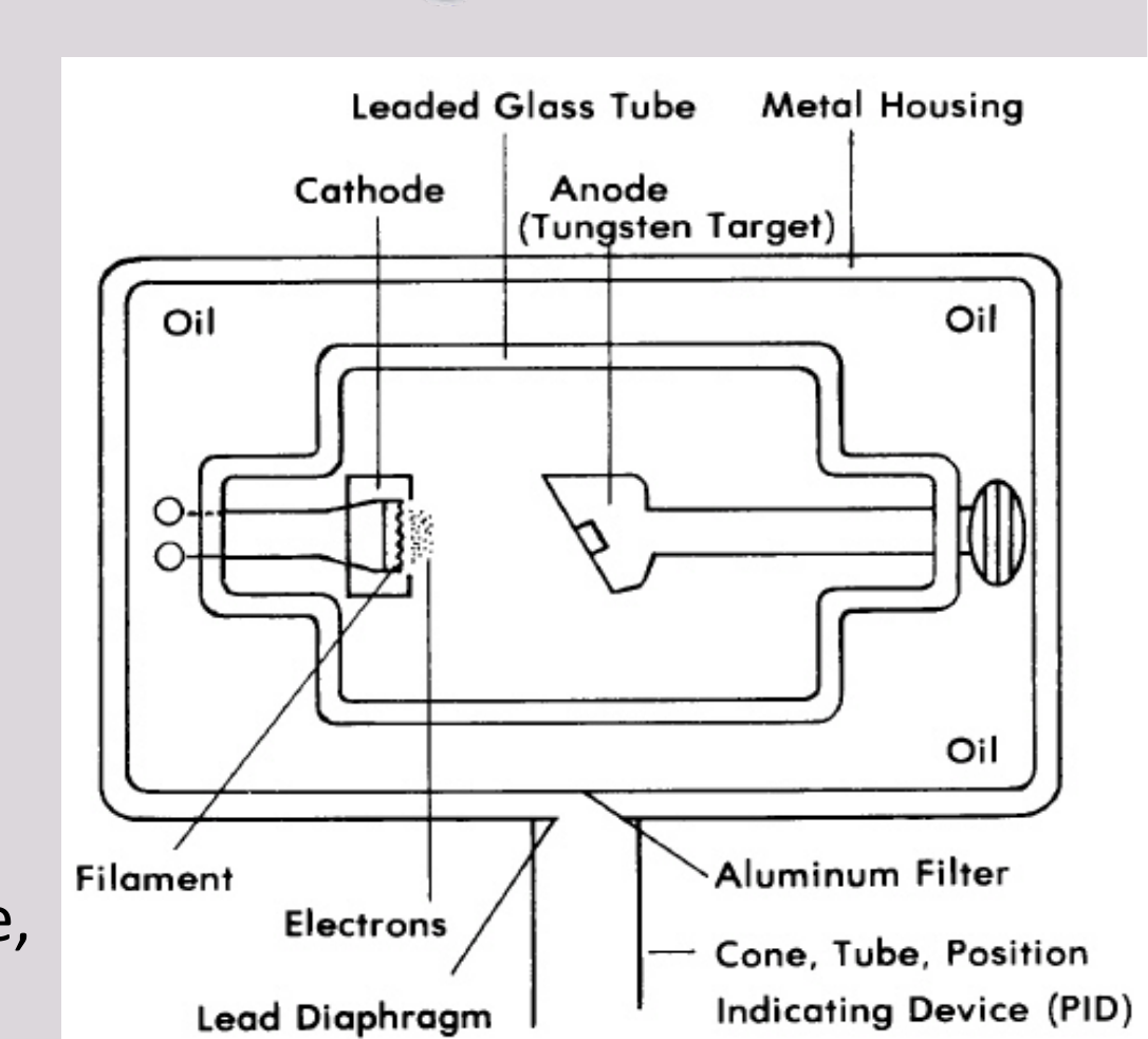
- Primary components of a tube head include:
- X-ray tube and power supply
- Other components:
- An electrical insulating material, usually oil, surrounds the x-ray tube (conducts heat away from the x-ray tube).
- Lead Casing/Glass: Removes scattered x-rays.
- Aluminium Filter: removes soft (low energy) x-rays from the primary beam.
- PID (position indicating device; 200mm in length) → provides optimum distance (least divergence & unclearness)
- Collimator (opening) → restricts beam to usable size
- Entire tube head is supported by an arm that is mounted on a wall.
- Control panel available for adjusting: duration of exposure, and energy and exposure rate of the x-ray beam.
X-ray Tube
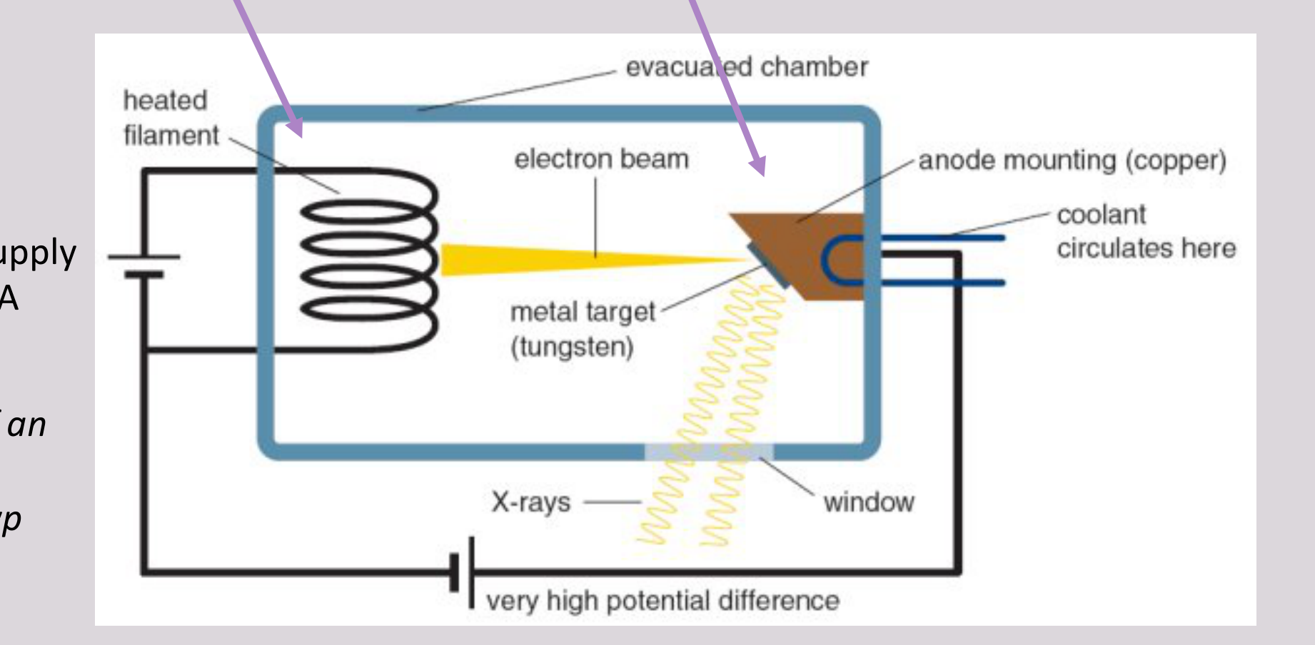
- Composed of a cathode (-ve) and an anode (+ve) within an evacuated glass/tube.
Power Supply kVp & mA
Typically, kVp of an intraoral x-ray machine is 70 kVp.
Cathode Tungsten filament Molybdenum cup Anode Electron stream Tungsten target Copper stem Unleaded glass window X-ray beam Vacuum Leaded-glass housing
 |  |
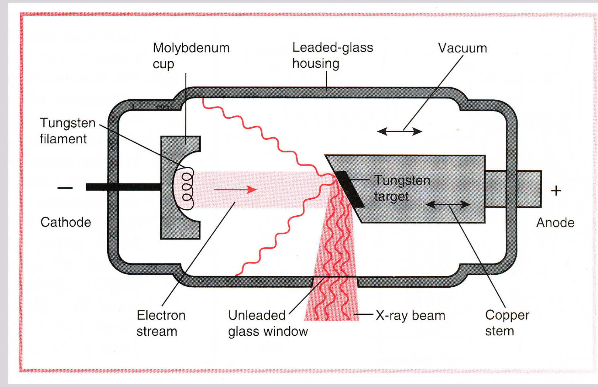 |
Cathode and Anode Functions
Cathode (-)18
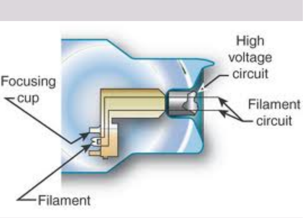
- The cathode (-ve) consists of a tungsten filament and a molybdenum focusing cup. The filament is the source of electrons within the x-ray tube.
- The filament is heated by the flow of current from the low-voltage source (~ 10 volts) and emits electrons at a rate proportional to the temperature of the filament.
- Focusing cup is also negatively charged.
- Concave shape and charge serve to focus the electrons into a beam that is aimed at the focal spot on the anode. (electron clouds)
- Electrons are then accelerated (gaining kinetic energy) by the second high-voltage source (60-100 kilovolts) and move / are attracted to the positively charged anode (focal spot).
- Diagram showing internal x-ray tube: Focusing cup (concave component left), Filament (small rod tip), High voltage circuit (top right electrical lead), and Filament circuit (bottom right electrical lead).
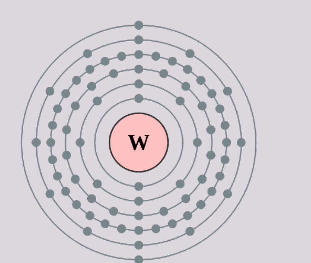
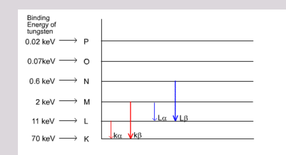
Tungsten Atom (Z = 74)19
- Electron volt binding energy decreases as the shell to nucleus distance increases.
- Tungsten has an K shell electron binding energy is approximately 70 keV.
- It has a high atomic number (74), a high melting point, high thermal conductivity, and low vapor pressure at the working temperatures of an x-ray tube.
- Tungsten has high thermal conductivity, thus readily dissipating its heat into the copper stem.
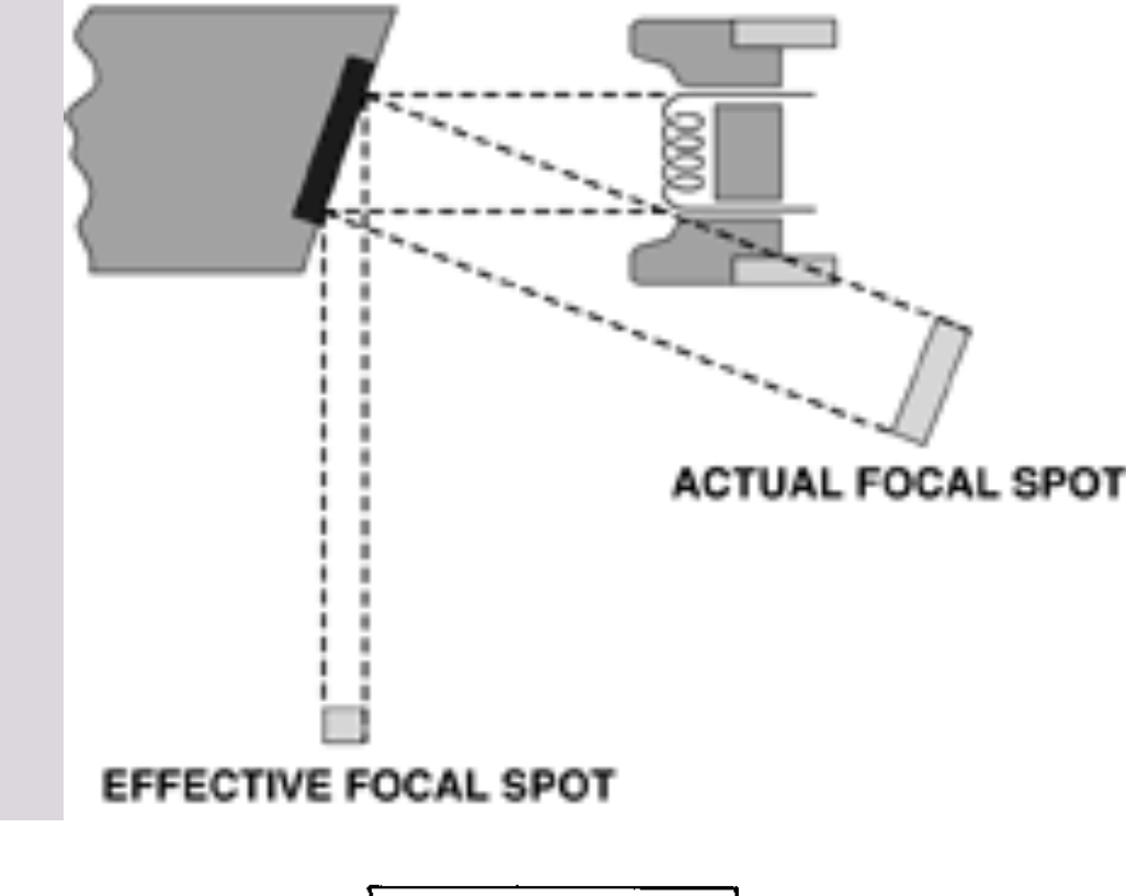
Anode (+)20
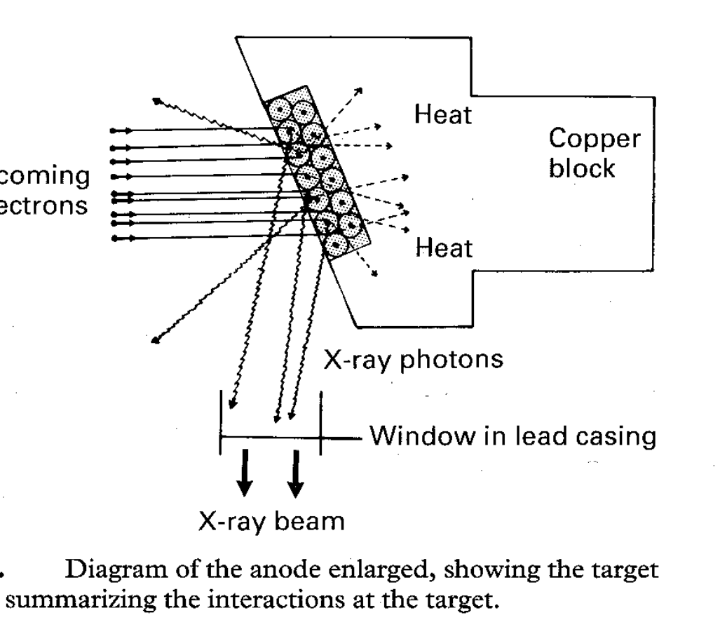
- Consists of a tungsten target in a copper stem.
- Typically, the target is placed at an angle (inclined about 20 degrees) to the electron beam
- to generate a much smaller (outgoing) beam → the more ‘focused’ the beam, the sharper the radiographic image at the expense of generating more heat
- Target converts the kinetic energy of the colliding electrons into x-ray photons.
- Conversion of the kinetic energy of the electrons into x-ray photons is an inefficient process as 99% of the electron kinetic energy converted to heat.
- A target made of a high atomic number material is most efficient in producing x rays.
- Copper stem removes heat from the tungsten, reducing the risk of the target melting.
- Additionally, the insulating oil carries heat away from the copper stem.
 |  |
Heat Production in the Tungsten Target2122
Heat Production in Tungsten Target (on Anode)
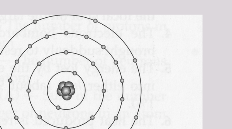
- Most high-speed electrons interacting with the tungsten target release their energy as heat (99%) ☹
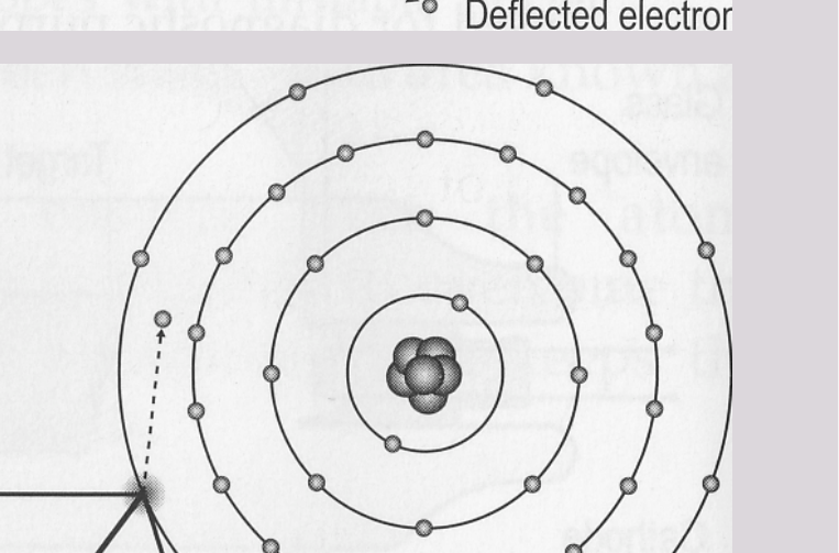
- Heat is produced the following ways:
- The incoming electron is deflected by the cloud of outer-shell target electrons with a small loss of energy in the form of heat
- The incoming electron collides with an outer shell target electron displacing the target electron to a more peripheral shell (excitation) or displacing the target electron from the atom (ionisation) with a small loss of energy in the form of heat
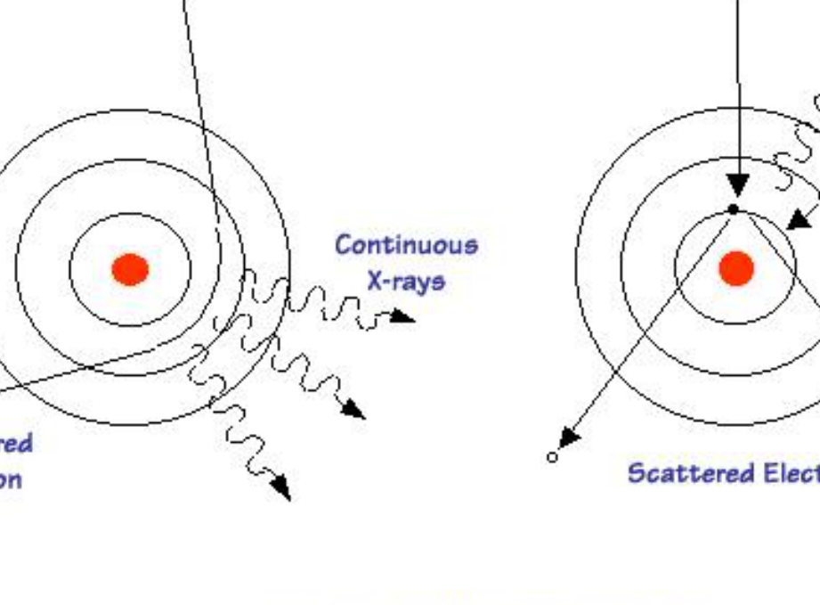
Bremsstrahlung radiation and characteristic radiation.
 |  |
 |
Mechanisms of X-ray Generation
Bremsstrahlung Radiation23
Bremsstrahlung = “Braking” in German
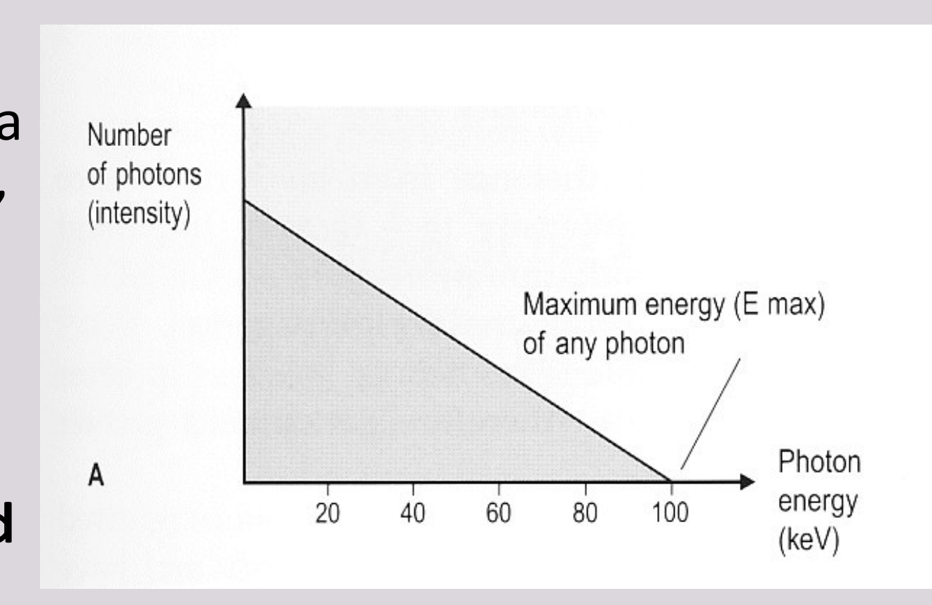
- More than 70% of dental x-rays
- Electrons’ sudden stopping or decrease in speed by tungsten nuclei causes the electrons to lose kinetic energy → producing bremsstrahlung photons
- The closer the electron approaches the nuclei, the greater the braking effect, and the greater the energy of the resulting bremsstrahlung photons.
- High Z (atomic number) metals (more protons) are more effective in deflecting the path of the incident electrons.
- Large deflections produce high-energy photons
- Small deflections produce low-energy photons
Bremsstrahlung Radiation cont’d.
- Reality → more low energy
- Resultant spectrum shows a large number of small energy photons and a small number of high energy photons, with a continuous spectrum in between
- Note: Low energy photons have little penetrating power and do not contribute to a useful x-ray beam and are removed by filtration.
Characteristic Radiation24
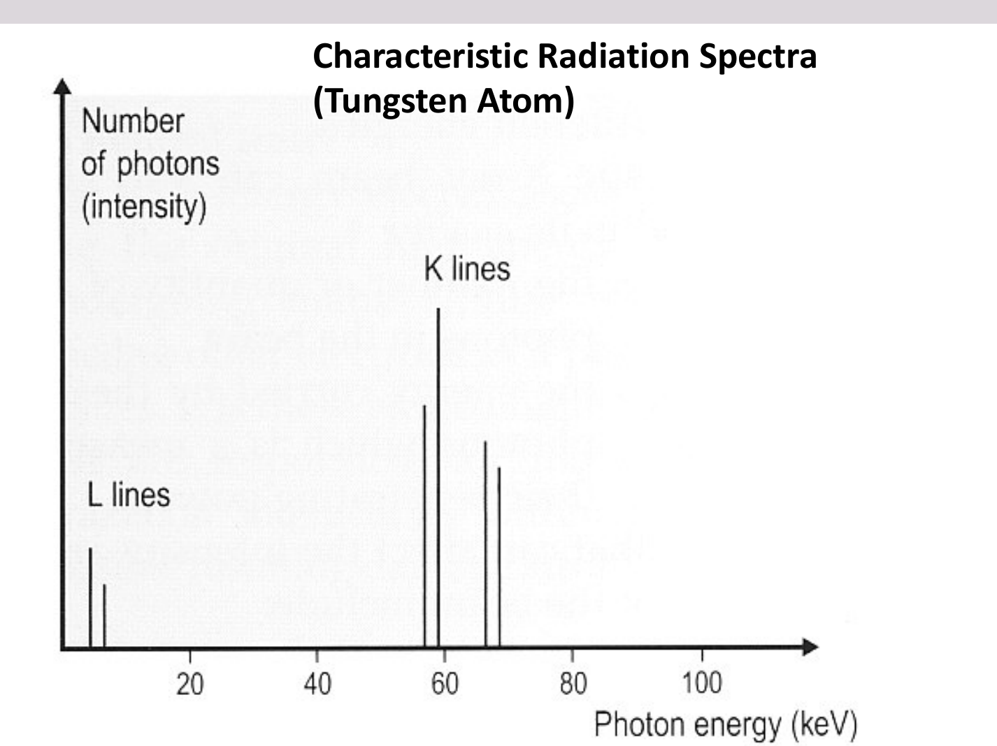
- Only a small fraction of dental x-rays
- Occurs when an incident electron (from the incoming beam) ejects an inner orbit electron from the tungsten target.
- The electron vacancy is filled by an electron from an outer orbit.
- A photon is emitted with energy equal to the difference in energy between the two orbits.
- The energies of characteristic photons are discrete because they represent the difference of the energy levels of electron orbital levels and hence are characteristic of the target atom.
Characteristic Radiation cont’d.
- Discrete, specific energies (characteristic) ie. no continuous spectrum
 |  |
Spectrum of X-ray Photons
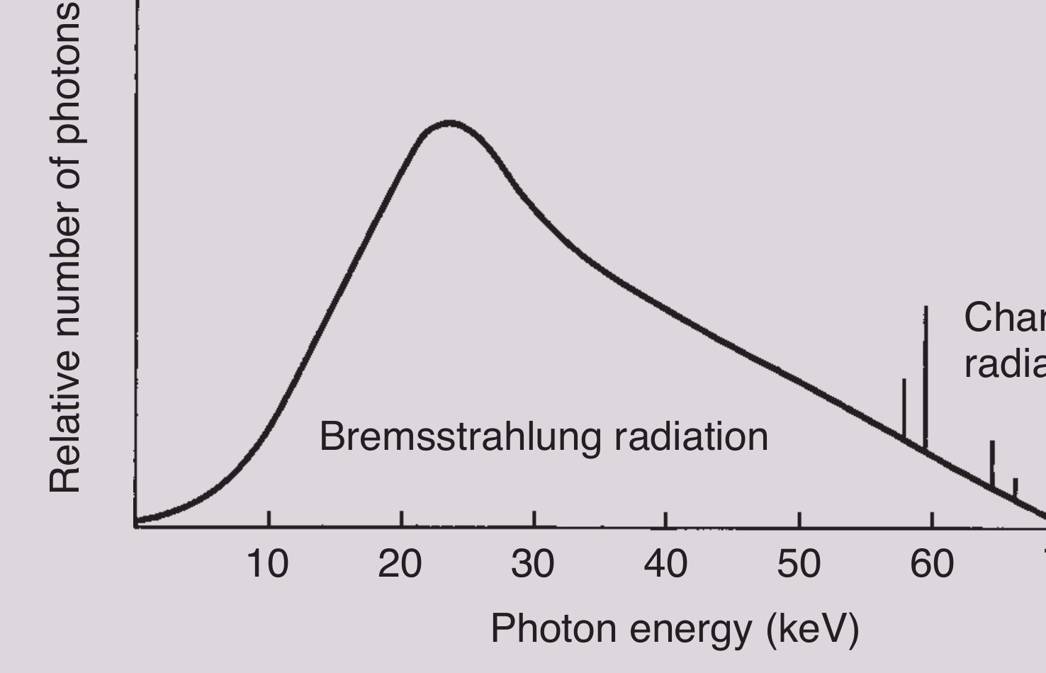
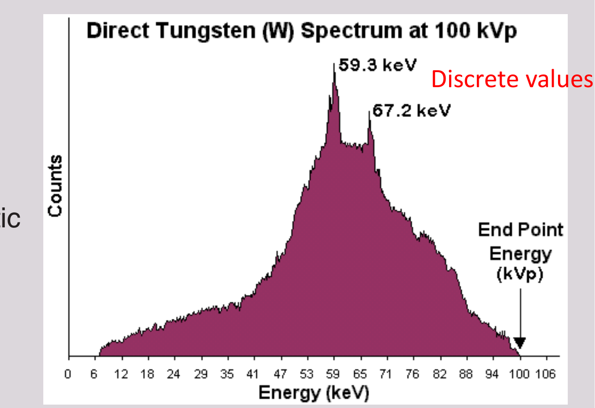
Spectrum of X-ray Photons (at 70 kVp & 100 kVp, Tungsten Target)25
Left Graph
- Y-axis: Relative number of photons
- X-axis: Photon energy (keV) [Scale: 10, 20, 30, 40, 50, 60, 70]
- Main Curve: Bremsstrahlung radiation
- Spikes: Characteristic radiation
Right Graph
- Title: Direct Tungsten (W) Spectrum at 100 kVp
- Y-axis: Counts
- X-axis: Energy (keV) [Scale: 0 to 106]
- Labeled Peaks (Discrete values):
- 59.3 keV
- 67.2 keV
- Labeled End Point:
- End Point Energy (kVp) at 100 keV
 |  |
Factors Controlling the X-ray Beam
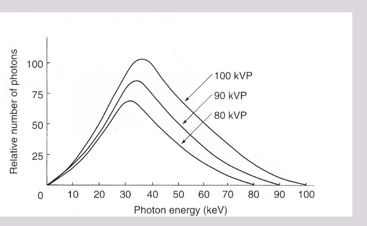
- Tube Voltage (kVp)
- Filtration
- Tube Current (mA)
- Duration (time in seconds)
- Collimation
- Target-Patient Distance
- Inverse-square law
Tube Voltage and Filtration26
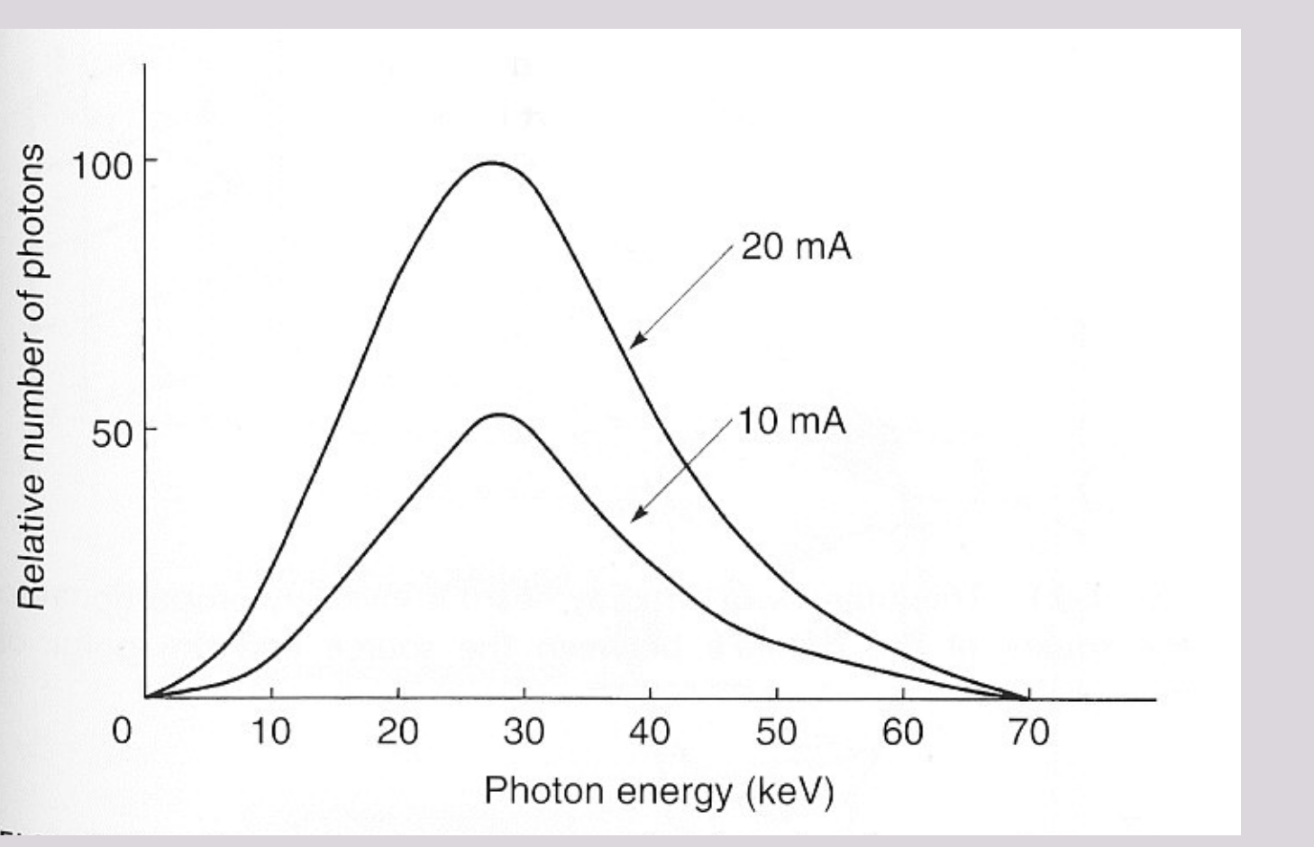
X-ray Altered by: Tube Voltage (kVp)27
- Spectrum of photon energies showing that as the kVp increases (mA constant) there is a corresponding increase in:
- the mean energy of the beam,
- the total number of photons emitted, and
- the maximum energy of the photons.
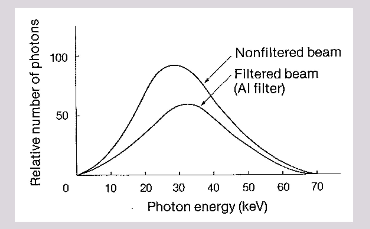
X-ray Altered by: Filtration of Beam28
- Filtration of an x-ray beam with aluminium results in the preferential removal of low-energy photons, reducing the intensity of the beam but increasing its mean energy. (also decrease in no. of photons)
(Note: The graph has “Relative number of photons” on the y-axis and “Photon energy (keV)” on the x-axis. It displays two curves: “Nonfiltered beam” (peaking around 90-100) and “Filtered beam (Al filter)” (peaking around 55-60).)
Exposure Time and Collimation
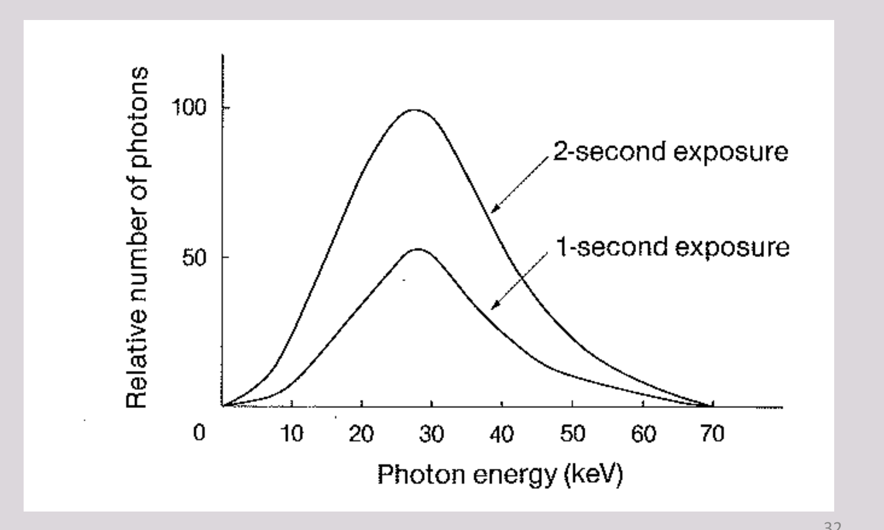
X-ray Altered by: Duration / Exposure Time29
- As the exposure time increases the total number of photons increases, but the mean energy and maximum energy of the beams are unchanged.
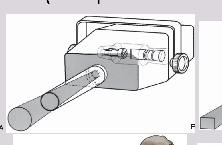
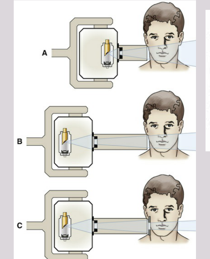
X-ray Altered by: Collimation (shape of the beam)30
- A collimator is a metallic barrier with an aperture in the middle used to reduce the size of the x-ray beam
- Dental x-ray beams are usually collimated to a circle (7 cm in diameter)
- Less frequently, there are rectangular collimators in dentistry
- Typically, round collimators are built into open-ended aiming cylinders.
- Rectangular collimators further limit the size of the beam to just larger than the x-ray film (intraoral x-ray films are rectangular), thereby further reducing patient exposure.
A | B
 |  |
Intensity and the Inverse Square Law
X-ray Altered by: Intensity / Distance31
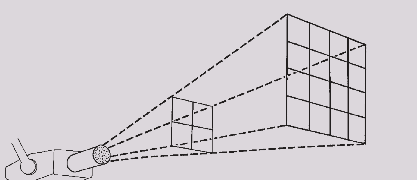
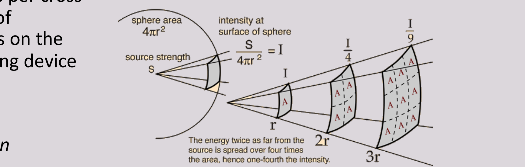
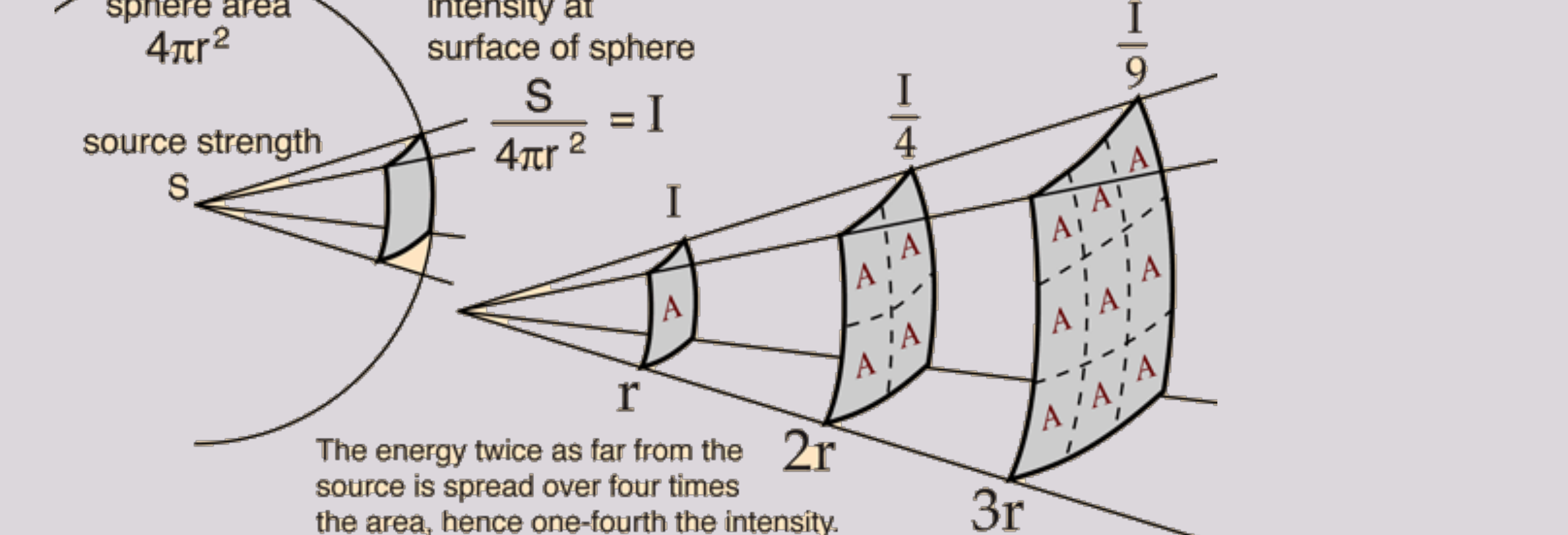
- Inverse Square Law = For a given beam, the intensity is inversely proportional to the square of the distance from the source
- The intensity of an x-ray beam (the number of photons per cross-sectional area per unit of exposure time) depends on the distance of the measuring device from the focal spot.
2x distance = ¼ x Radiation
Visual Description: The page contains two diagrams illustrating the Inverse Square Law. The top diagram shows an X-ray tube on the left emitting diverging dashed lines onto a grid of squares at two different distances (nearer and farther) to demonstrate beam divergence. The bottom diagram shows a source point emitting rays outward through three cross-sections marked A, , and , with labels for sphere area () and intensity (), along with fractions representing intensity (, ).
 |  |
Radiation Safety3233
How to minimise radiation for patient and staff?
- X-ray & Tissue (eg. Patient) Interaction
- Direct and Indirect Damage
- Biological Effects of X-rays (& all other ionising radiation)
- Dosimetry
- Other Sources of Ionising Radiation (Patient Education)
- How to minimise radiation in clinic?
X-ray Interactions with Matter
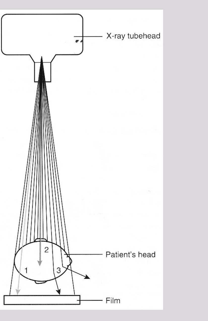
Patient Interactions with X-ray Photon34
3 possible outcomes:
- X-ray photons pass through patient without any interaction
- X-ray photons are completely absorbed by patient
- X-ray photons are scattered (coherent and incoherent)
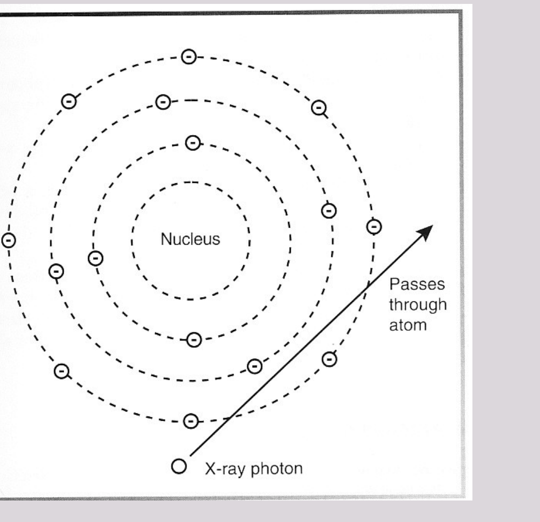
No Interaction with Tissues (Atoms)35
- X-ray photon passes through atom unchanged
- These photons contact the film emulsion or receptor to produce an area of darker density
- ~9% of the primary photons
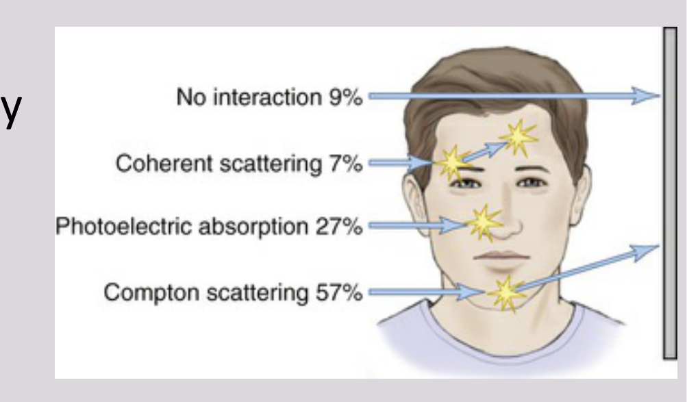
X-ray Absorption & Scattering36
- As the x-ray beam passes through tissues, photons get absorbed or scattered by the tissues, resulting in decreased energy of the beam
- Beam attenuation: reduction of the x-ray beam intensity as it passes through tissues.
- In a dental x-ray beam, there are three means of beam attenuation:
-
- Photoelectric absorption (~27%)
-
- Thompson/Coherent scattering (~7%)
-
- Compton/Incoherent scattering (~57% of the primary beam)
-
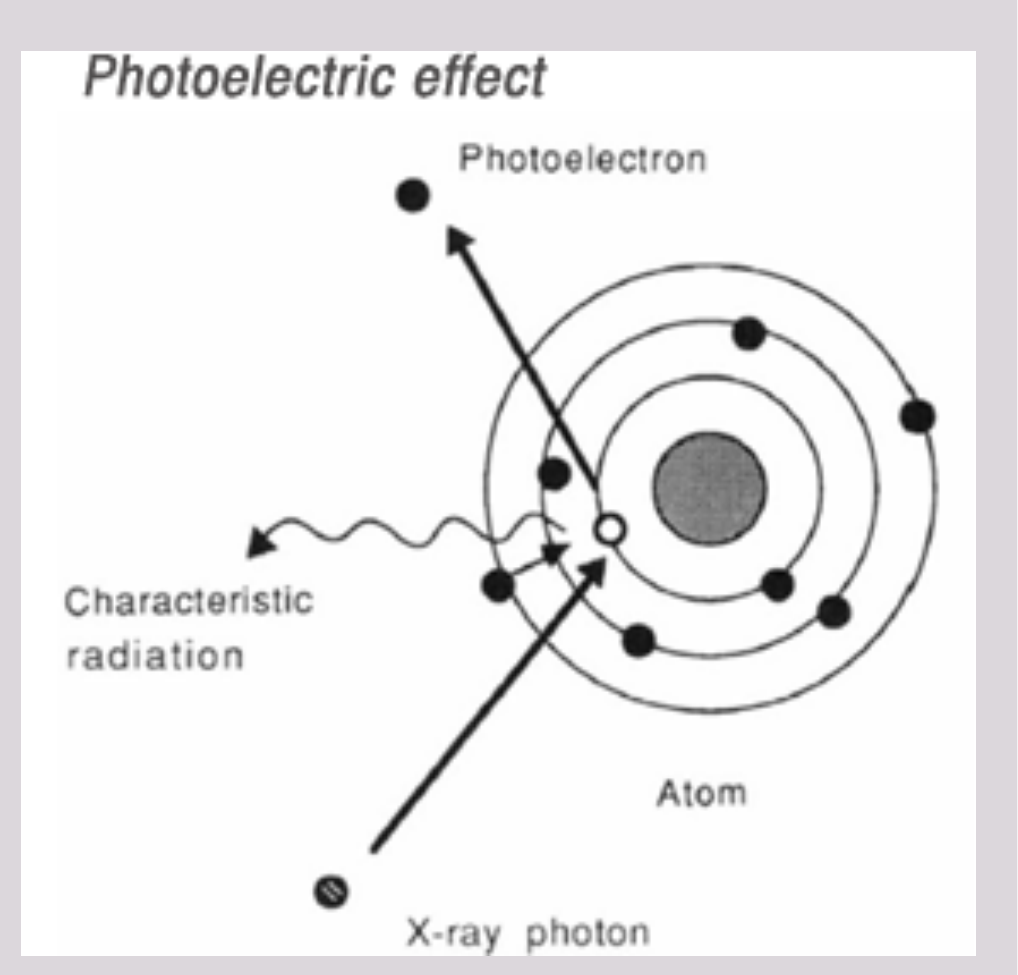
Photoelectric Absorption37
Incident photon interacts with an inner orbital electron of an atom in the patient.
Incident photon gives up all of its energy and ceases to exist.
Incident photon ejects the electron from its inner orbital, and it becomes a recoil electron (photoelectron).
An atom that has participated in a photoelectric interaction is ionized as result of the loss of an electron.
Electron deficiency is instantly filled, releasing characteristic radiation.
The characteristic photons generated are of such low energy that they are absorbed within the patient and do not fog the film.
Primary contributor to diagnostic imaging.
Coherent and Compton Scattering
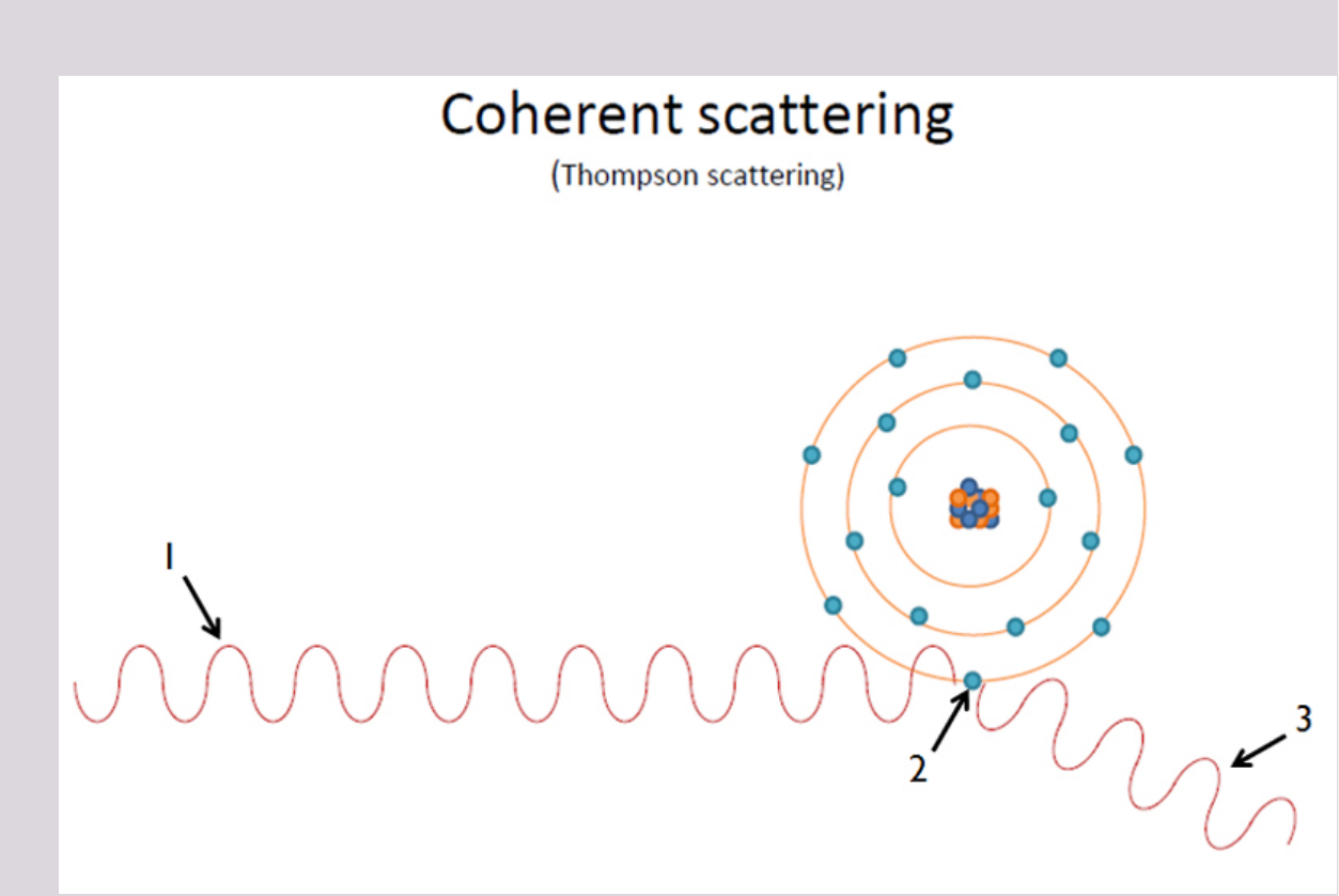
Coherent Scattering / Thompson Scattering38
- Occurs minimally (7%)
- Low-energy incident photon (<10 keV) interacts with a whole atom (patient’s)
- Atom becomes momentarily excited and incident photon ceases to exist.
- Excited atom returns to the ground state and generates another x-ray photon with the same frequency (energy) as the incident photon, however this secondary photon is emitted in a different direction than the path of the incident photon (scattered).
Coherent scattering contributes little to film fog (reduced image contrast)
- Too low energy
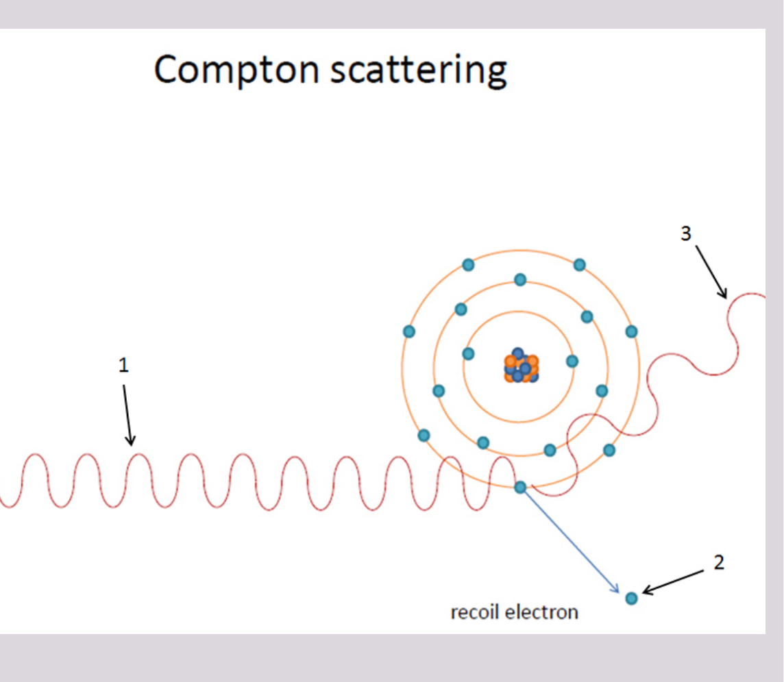
Compton Scattering39
- About 57% of interactions in a dental x-ray beam exposure involve Compton scattering.
- Occurs when a photon interacts with an outer orbital electron.
- Recoil electron: collided electron receives kinetic energy and recoils from the point of impact.
- Scattered photon: the path of the incident photon is deflected by this interaction and is scattered in a new direction.
- As with photoelectric absorption, Compton scattering results in the loss of an electron and ionization of the absorbing atom.
- Scattered photons travel in all directions, carry no useful information and degrade the image by reducing contrast (film fog).
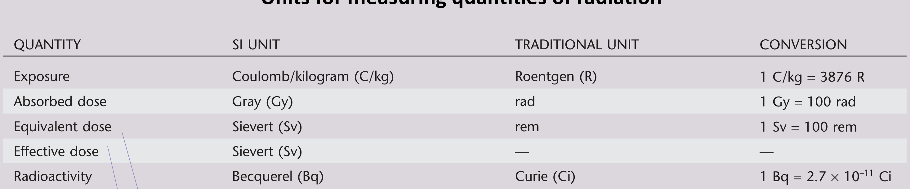
Sources of Ionizing Radiation4041
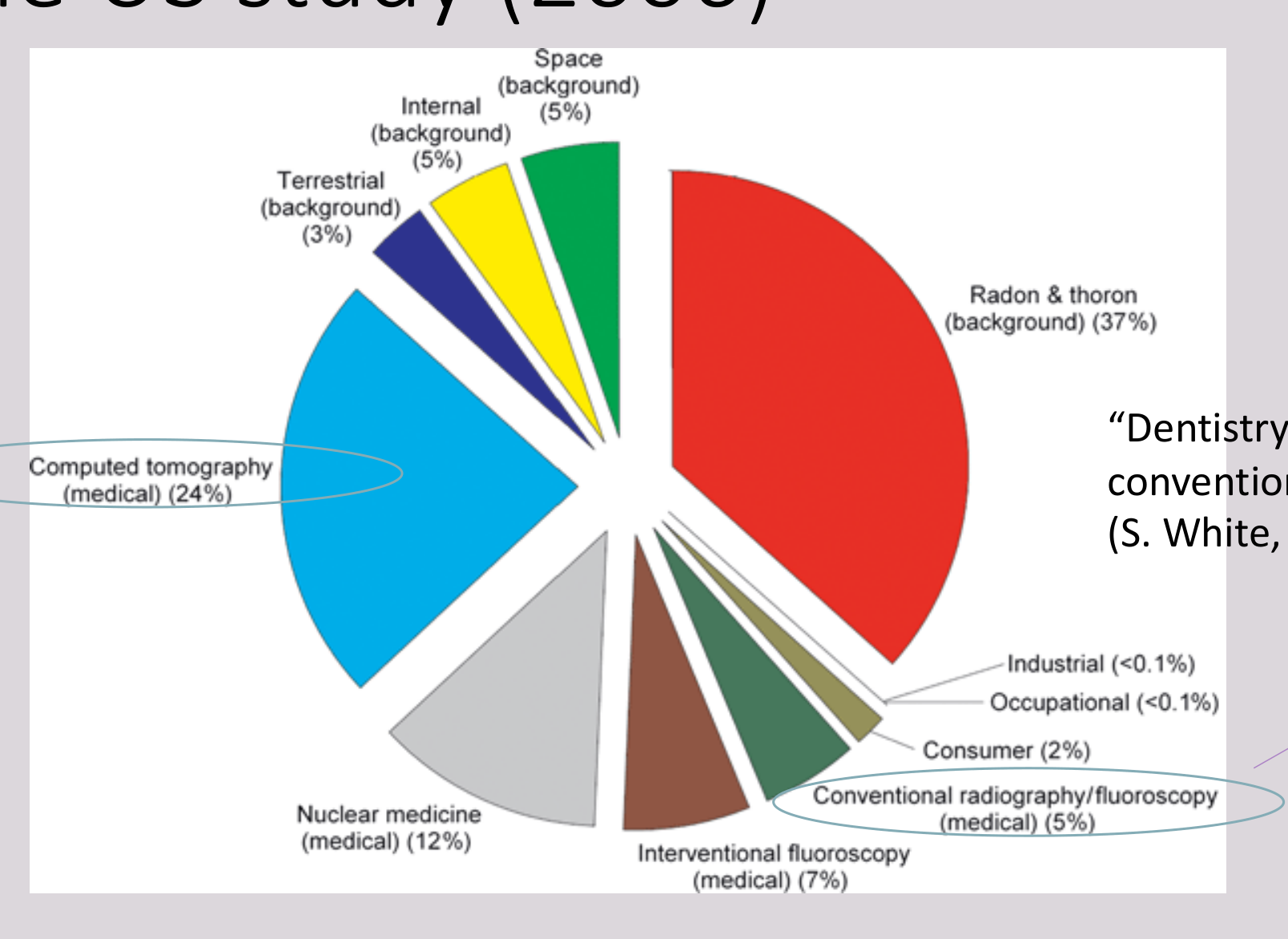 |  |
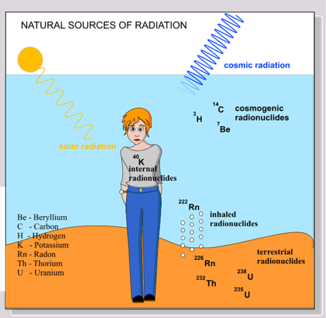
Natural Source42
- Background radiation (cosmic, terrestrial, etc.)
- Approx. each person receives 2 mSv per year
- 1 day of background radiation = ~0.005 mSv
 |  |
Artificial Source
- Medical & Dental
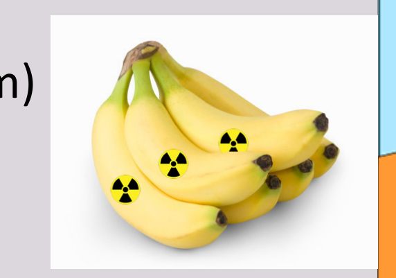
- Consumed products (potassium)
- Occupational
- Nuclear
Natural >>> Artificial per year
solar radiation —— o ——— 14C cosmogenic radionuclides 3H 7Be 40K internal radionuclides 222Rn inhaled radionuclides 226Rn 232Th 238U 235U terrestrial radionuclides
Be - Beryllium C - Carbon H - Hydrogen K - Potassium Rn - Radon Th - Thorium U - Uranium
In the US study (2006)
Dosimetry and Dose Limits
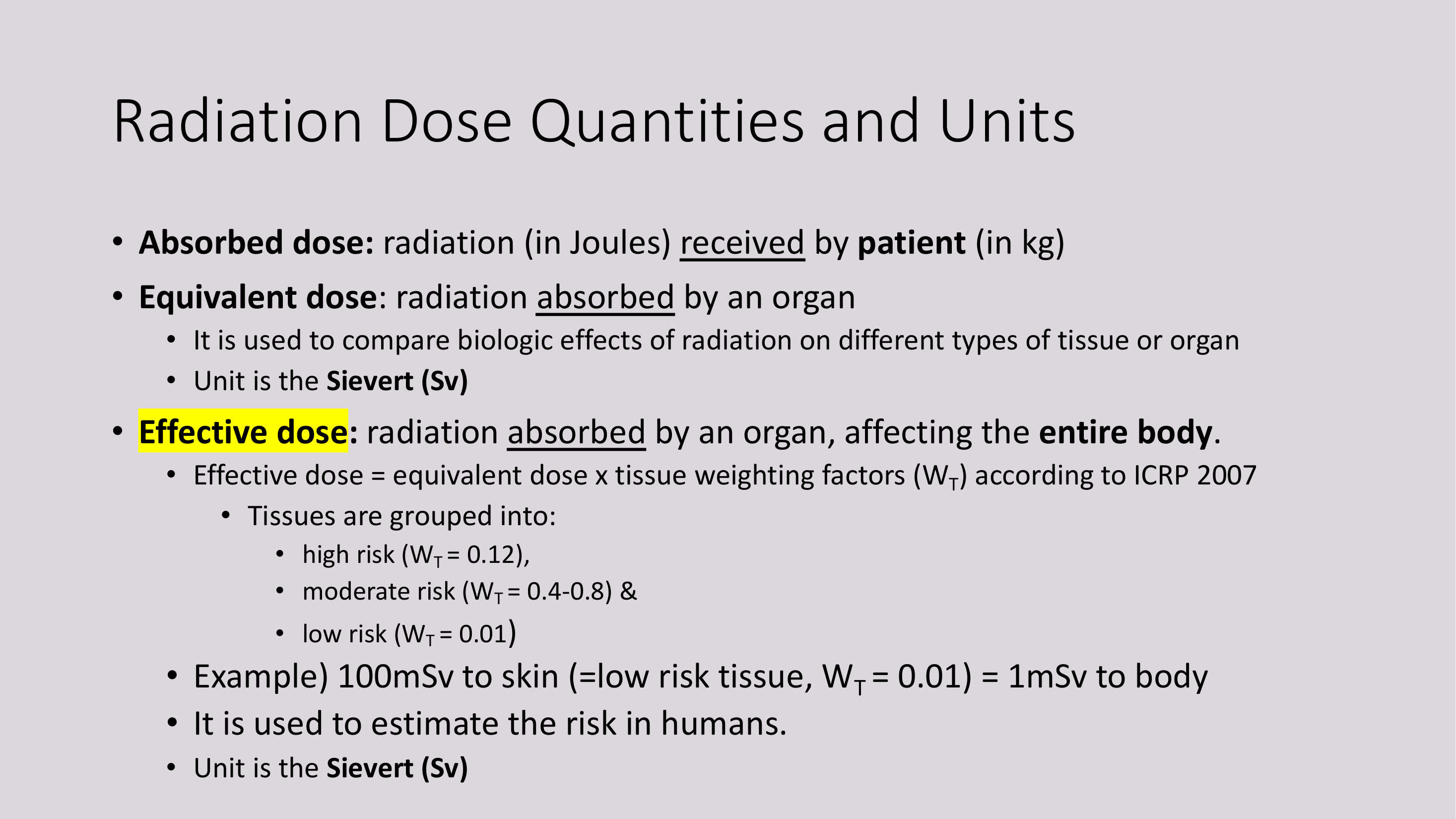
Radiation Dose Quantities and Units43
- Absorbed dose: radiation (in Joules) received by patient (in kg)
- Equivalent dose: radiation absorbed by an organ
- It is used to compare biologic effects of radiation on different types of tissue or organ
- Unit is the Sievert (Sv)
- Effective dose: radiation absorbed by an organ, affecting the entire body.
- Effective dose = equivalent dose x tissue weighting factors (WT) according to ICRP 2007
- Tissues are grouped into:
- high risk (WT = 0.12),
- moderate risk (WT = 0.4-0.8) &
- low risk (WT = 0.01)
- Tissues are grouped into:
- Example) 100mSv to skin (=low risk tissue, WT = 0.01) = 1mSv to body
- It is used to estimate the risk in humans.
- Unit is the Sievert (Sv)
- Effective dose = equivalent dose x tissue weighting factors (WT) according to ICRP 2007
Tissue Weighting and Radiosensitivity44
Tissue Weighting Factors & Radiosensitivity
 |  |
ICRP 2007 Tissue Weighting Factors
| Organs/tissue | 2007 WT |
|---|---|
| Gonads | 0.08 |
| Bone marrow (red) | 0.12 |
| Colon | 0.12 |
| Lung | 0.12 |
| Stomach | 0.12 |
| Bladder | 0.04 |
| Breast | 0.12 |
| Liver | 0.04 |
| Oesophagus | 0.04 |
| Thyroid | 0.04 |
| Skin | 0.01 |
| Bone surface | 0.01 |
| Brain | 0.01 |
| Salivary glands | 0.01 |
| Remainder | 0.12* |
Radiosensitivity List
- BLOOD CELLS
- REPRODUCTIVE CELLS
- YOUNG BONE
- SKIN
- GLANDS
- MUSCLE
- NERVE
- MATURE BONE
List of types of cells in order of sensitivity to x rays.
Sensitive Cells Description
Sensitive cells are more susceptible to damage:
- Cells with a high mitotic activity
- Cells with a high metabolic activity
- Pluripotent (primitive) cells
- Eg. Children
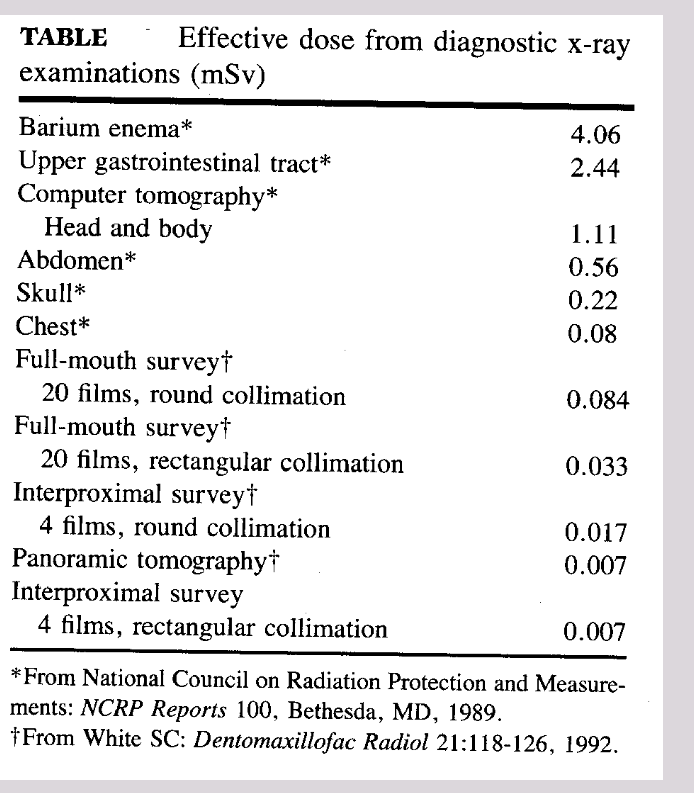
| Effective dose from diagnostic x-ray examinations (mSv) | |
|---|---|
| Barium enema* | 4.06 |
| Upper gastrointestinal tract* | 2.44 |
| Computer tomography* | |
| Head and body | 1.11 |
| Abdomen* | 0.56 |
| Skull* | 0.22 |
| Chest* | 0.08 |
| Full-mouth survey† | |
| 20 films, round collimation | 0.084 |
| 20 films, rectangular collimation | 0.033 |
| Interproximal survey† | |
| 4 films, round collimation | 0.017 |
| Panoramic tomography† | 0.007 |
| Interproximal survey | |
| 4 films, rectangular collimation | 0.007 |
From National Council on Radiation Protection and Measurements: NCRP Reports 100, Bethesda, MD, 1989. †From White SC: Dentomaxillofac Radiol 21:118-126, 1992.
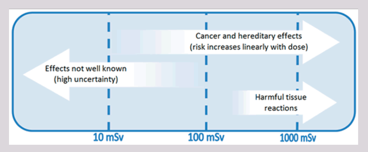
Dose Thresholds (from top graphic)
- 10 mSv
- 100 mSv
- 1000 mSv
Intra-oral x-ray (bitewing / PA) = ~4μSv (0.004mSv) → Comparable to daily Australian background radiation (4-5μSv at sea level) OPG ~ 10μSv Ceph view ~5μSv CBCT varies from 5 to 1073 μSv (depends on many factors)
Annual Occupational and Public Dose Limits
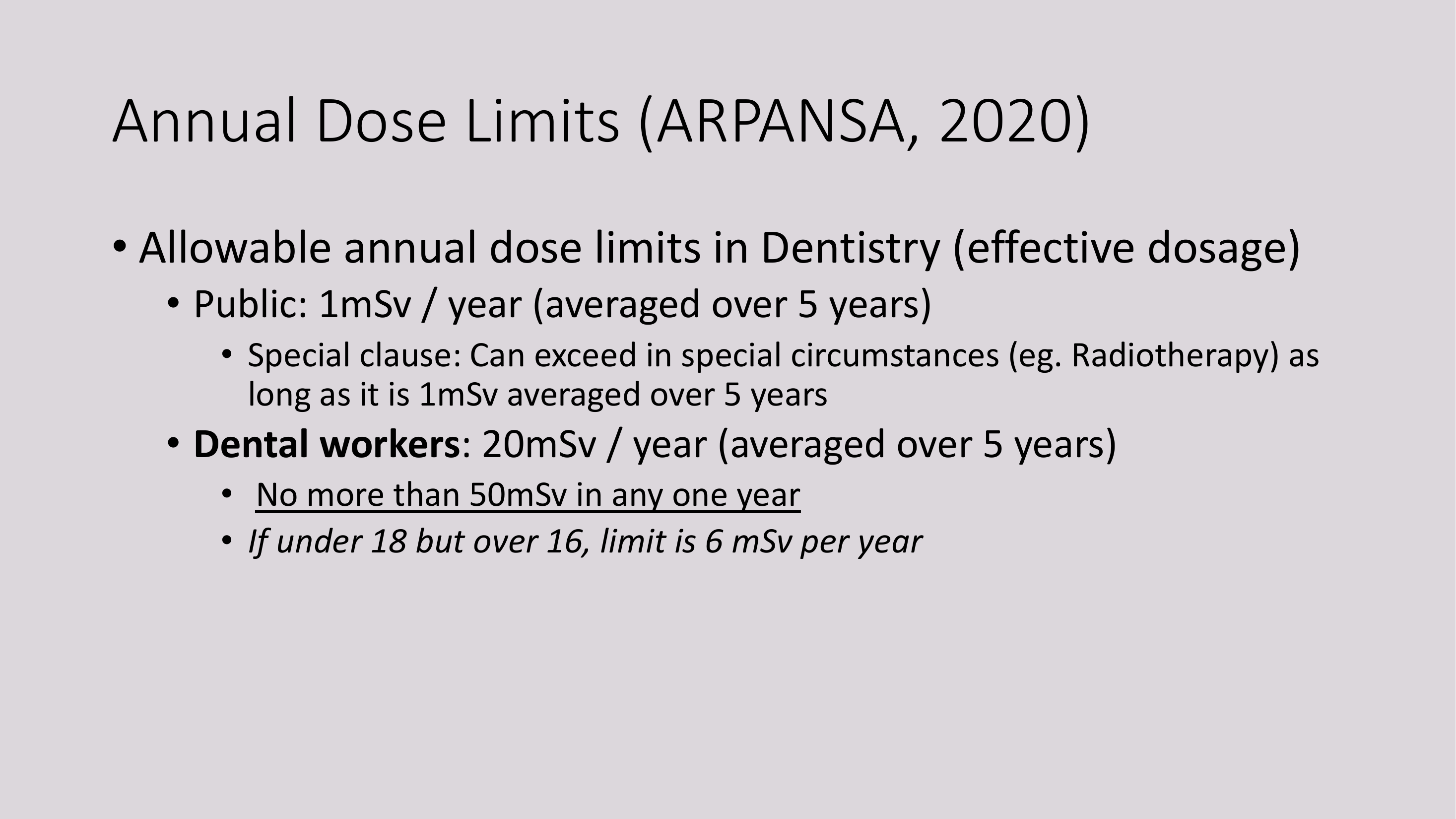
Annual Dose Limits (ARPANSA, 2020)45
- Allowable annual dose limits in Dentistry (effective dosage)
- Public: 1mSv / year (averaged over 5 years)
- Special clause: Can exceed in special circumstances (eg. Radiotherapy) as long as it is 1mSv averaged over 5 years
- Dental workers: 20mSv / year (averaged over 5 years)
- No more than 50mSv in any one year
- If under 18 but over 16, limit is 6 mSv per year
- Public: 1mSv / year (averaged over 5 years)
Biological Effects of Ionizing Radiation
Ionising Radiation & Cell Damage46
- It may pass directly through the cell without causing any damage
- It may interact with cells and cause DAMAGE
Cells can either:
- Repair itself
- Mutate, or
- Die
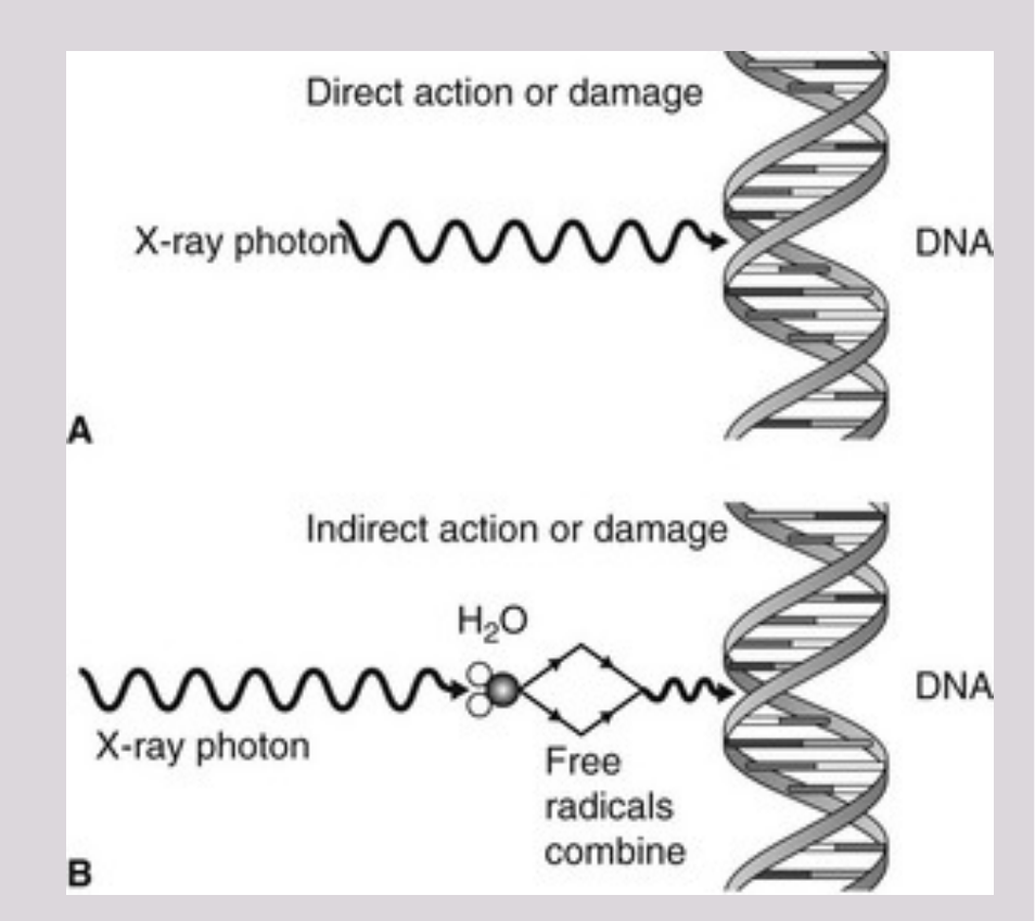
Direct and Indirect Cell Damage4748
- Damage to cell walls, mitochondria, mRNA, nuclear membrane, DNA, etc.
- DIRECT damage:
- 25%-30% of total damage
- Direct damage to atoms / molecules eg. DNA
- INDIRECT damage:
- 70%-75% of total damage
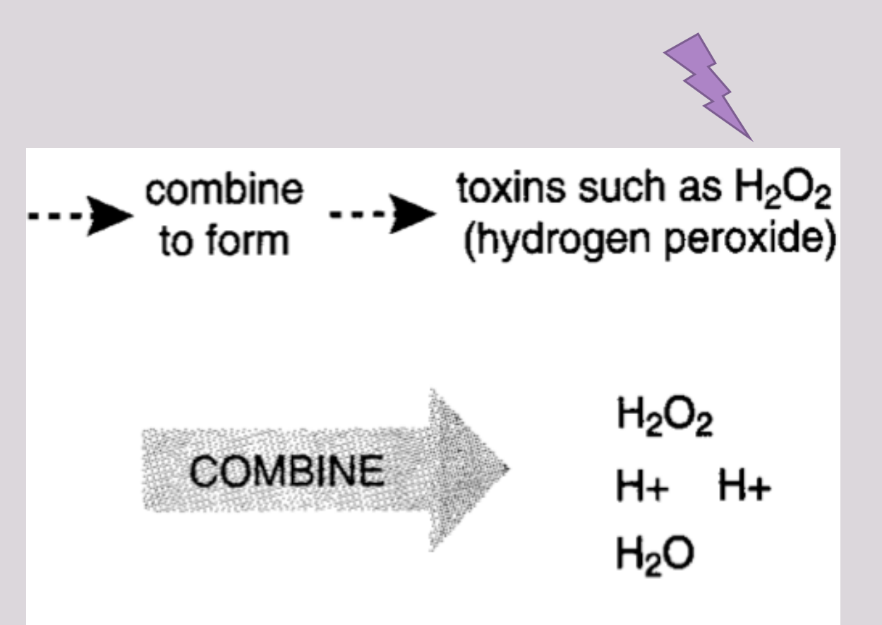
- Radiolysis of water (in cells) → release of toxic free radicals
- Changes to DNA result in:
- Changes in genetically sensitive information
- Changes in structural protein synthesis
- Changes in enzyme structure and function and enzyme substrate
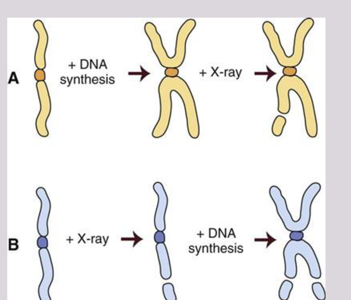
DNA Damage
- When only one strand is damaged (single strand defects/breaks), the other strand can be used as a template to guide the correction of the damaged strand. → repair
- Double strand breaks are hard to repair and often result in cell death.
 |  |
Direct Damage49
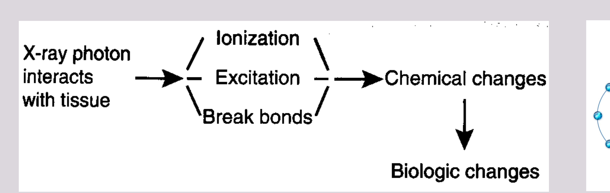
Flowchart
| Input | Processes | Result | Outcome |
|---|---|---|---|
| X-ray photon interacts with tissue | Ionization, Excitation, Break bonds | Chemical changes | Biologic changes |
Molecule Comparison
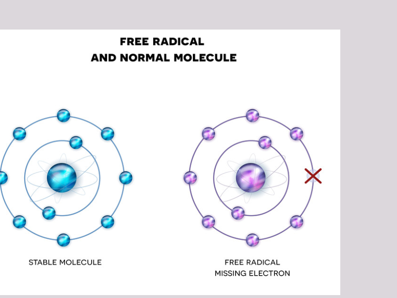
FREE RADICAL AND NORMAL MOLECULE
STABLE MOLECULE FREE RADICAL MISSING ELECTRON
- When an atom becomes ionized, it become unstable = free radicals, which are highly reactive and short-lived
- Free radicals then quickly stabilize by dissociation (breaking apart) or cross-linking
- Structurally and functionally different molecules and a consequent biologic change.
 |  |
Dissociation and Cross-linking50
Molecule (RH) becomes Free Radical R*
Free radical production: RH + x-radiation → R* + H+ + e−
Free radical fates: Dissociation: Breaking apart R* → X + Y*
Cross-linking: R* + S* → RS
Formation of structurally and functionally different molecules
Joining of two molecules

Indirect Damage51
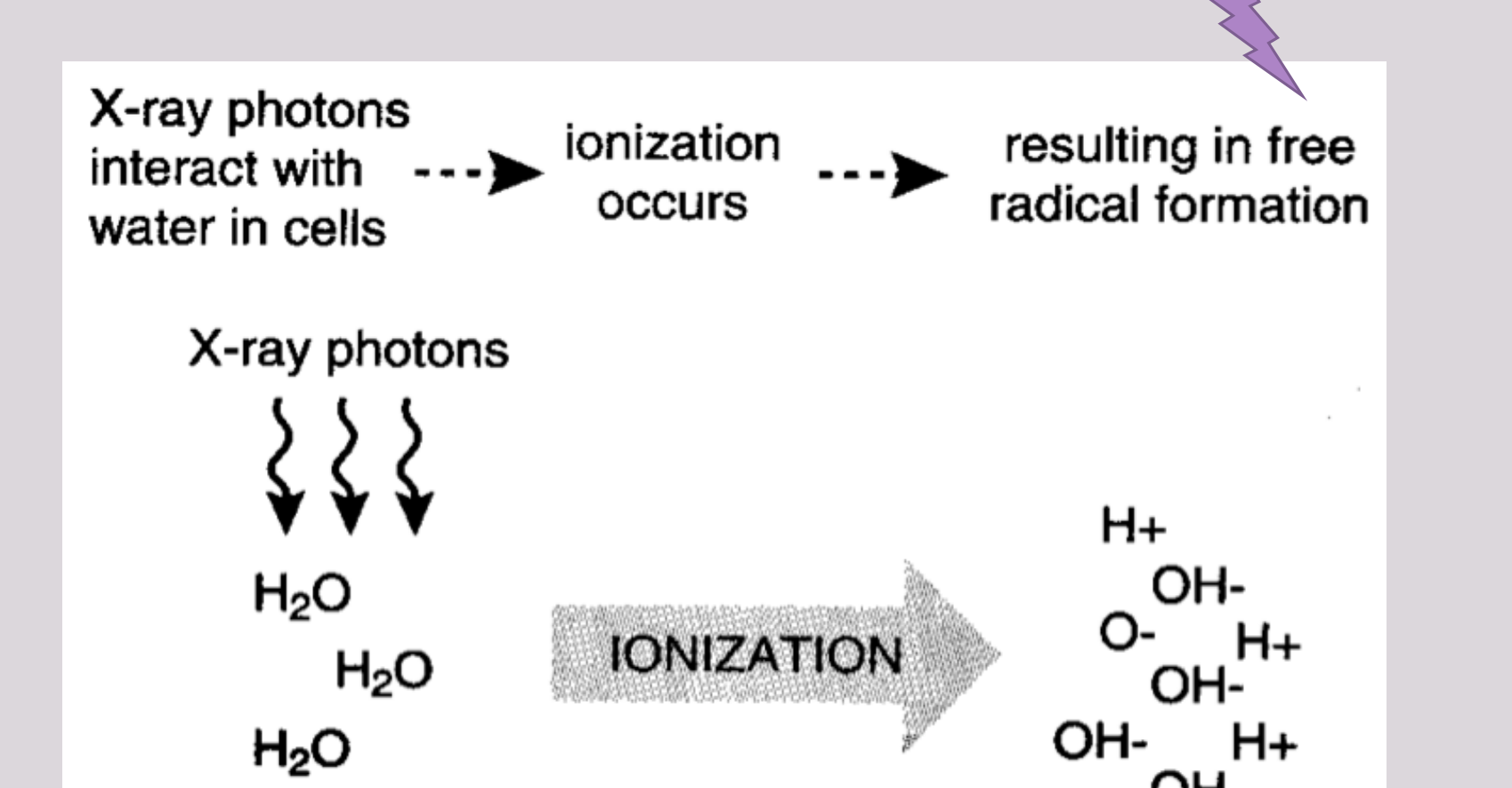
X-ray photons interact with water in cells ionization occurs resulting in free radical formation
X-ray photons H2O H2O H2O IONIZATION H+ OH- O- H+ OH- H+ OH- OH-
Oxidative damage to cells
 |  |
Stochastic and Deterministic Effects
Stochastic and Non-stochastic Effects52
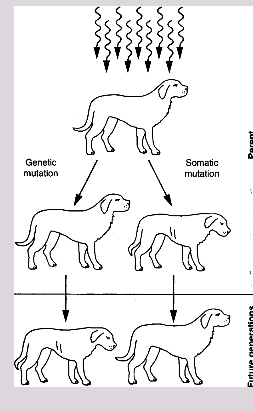
- Stochastic effects on somatic tissues
- Stochastic effects on genetic tissues
- Non-stochastic effects / Deterministic effects (always on somatic tissues)
Somatic Stochastic Effect53
- ‘Somatic’ = body cells
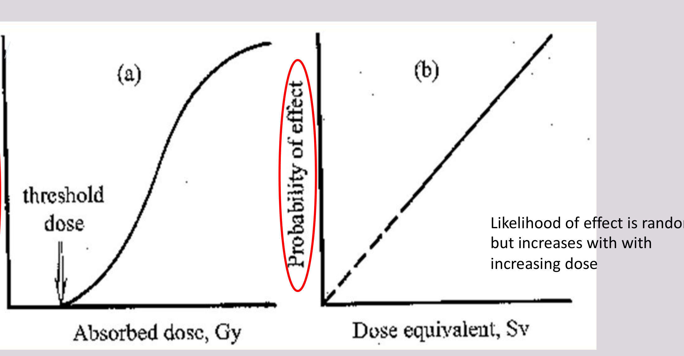
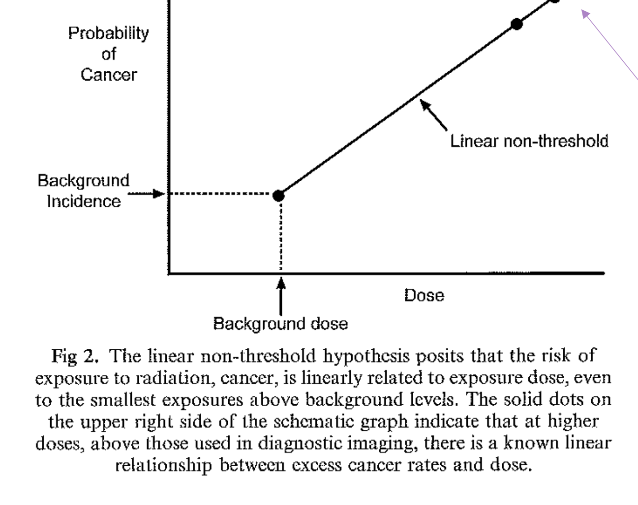
- Probability of the change occurring (not severity) of which, is greater for a higher radiation dose
- No safe dose (= no threshold)
- Therefore, every exposure has the possibility of producing a stochastic effect
- Cancer
Genetic Stochastic Effect54
- Reproductive organs
- Damage to gonad / reproductive cells can result in congenital abnormality of the offspring
- No safe threshold
- Risk of inducing a heritable mutation is estimated to be about 2 in 100,000 per mSv
Non-stochastic / Deterministic Effect555657585960
- Somatic tissues
- Severity of the change is proportional to dose
- There is a threshold dose below which no effect is seen
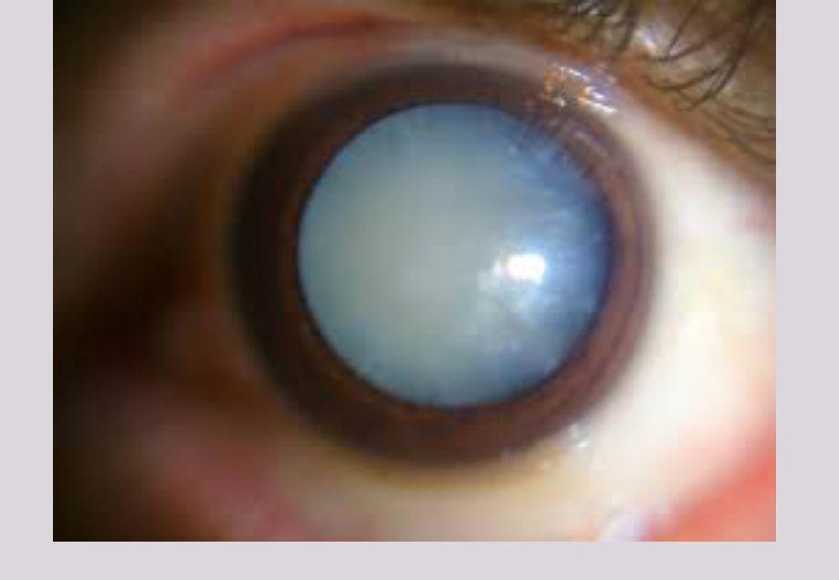
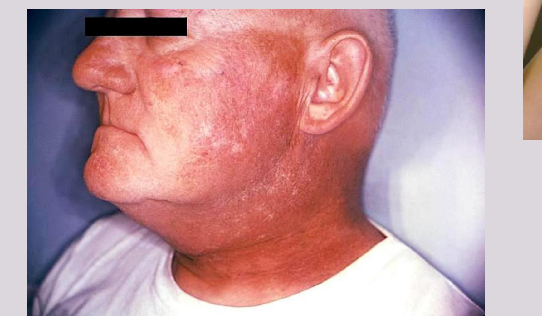
- Biological Changes: loss of somatic function (> 1Gy → not seen in dental)
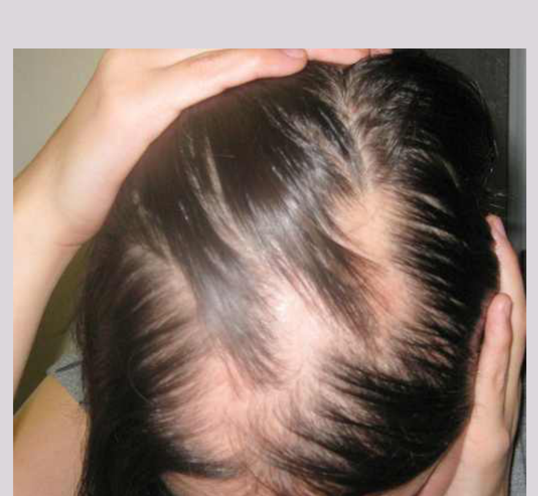
- Xerostomia, loss of taste, skin reddening, hair loss, cataract formation
- Severe = death
The image displays three images: an eye with a cloudy lens, a face with red skin, and a top of a head with thinning hair.
There is no text on or related to this image that can be extracted.
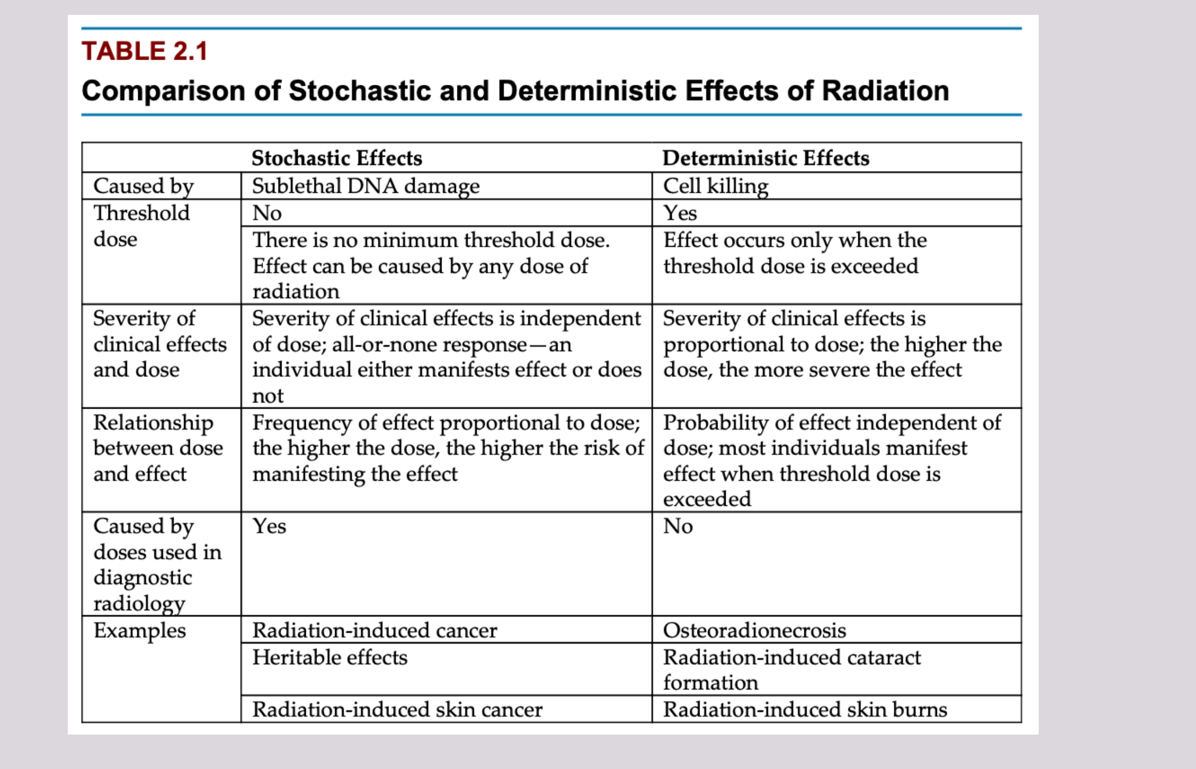
TABLE 2.1
Comparison of Stochastic and Deterministic Effects of Radiation
| Stochastic Effects | Deterministic Effects | |
|---|---|---|
| Caused by | Sublethal DNA damage | Cell killing |
| Threshold dose | No There is no minimum threshold dose. Effect can be caused by any dose of radiation | Yes Effect occurs only when the threshold dose is exceeded |
| Severity of clinical effects and dose | Severity of clinical effects is independent of dose; all-or-none response—an individual either manifests effect or does not | Severity of clinical effects is proportional to dose; the higher the dose, the more severe the effect |
| Relationship between dose and effect | Frequency of effect proportional to dose; the higher the dose, the higher the risk of manifesting the effect | Probability of effect independent of dose; most individuals manifest effect when threshold dose is exceeded |
| Caused by doses used in diagnostic radiology | Yes | No |
| Examples | Radiation-induced cancer Heritable effects Radiation-induced skin cancer | Osteoradionecrosis Radiation-induced cataract formation Radiation-induced skin burns |
HBO ORIGINAL CHERNOBYL
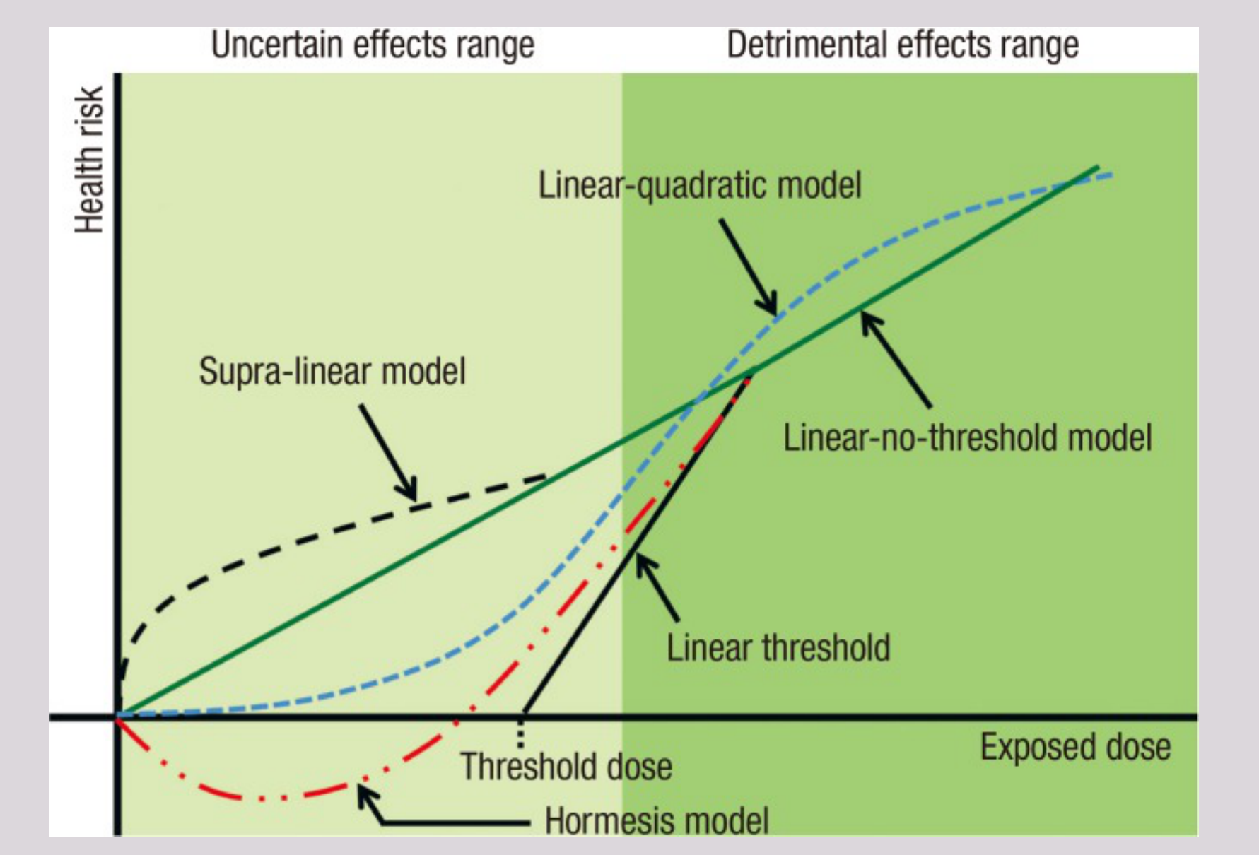
Fig 2. The linear non-threshold hypothesis posits that the risk of exposure to radiation, cancer, is linearly related to exposure dose, even to the smallest exposures above background levels. The solid dots on the upper right side of the schematic graph indicate that at higher doses, above those used in diagnostic imaging, there is a known linear relationship between excess cancer rates and dose.
3 accidents (>100mSv)
- Fukushima Daiichi nuclear accident
- Chernobyl → On-site workers received ~6 Sv (= 6000mSv), died in a month
- Three Mile Island (TMI) nuclear power plant accident
 |  |  |
 |  |  |
 |  |
Cumulative Effects and Repair
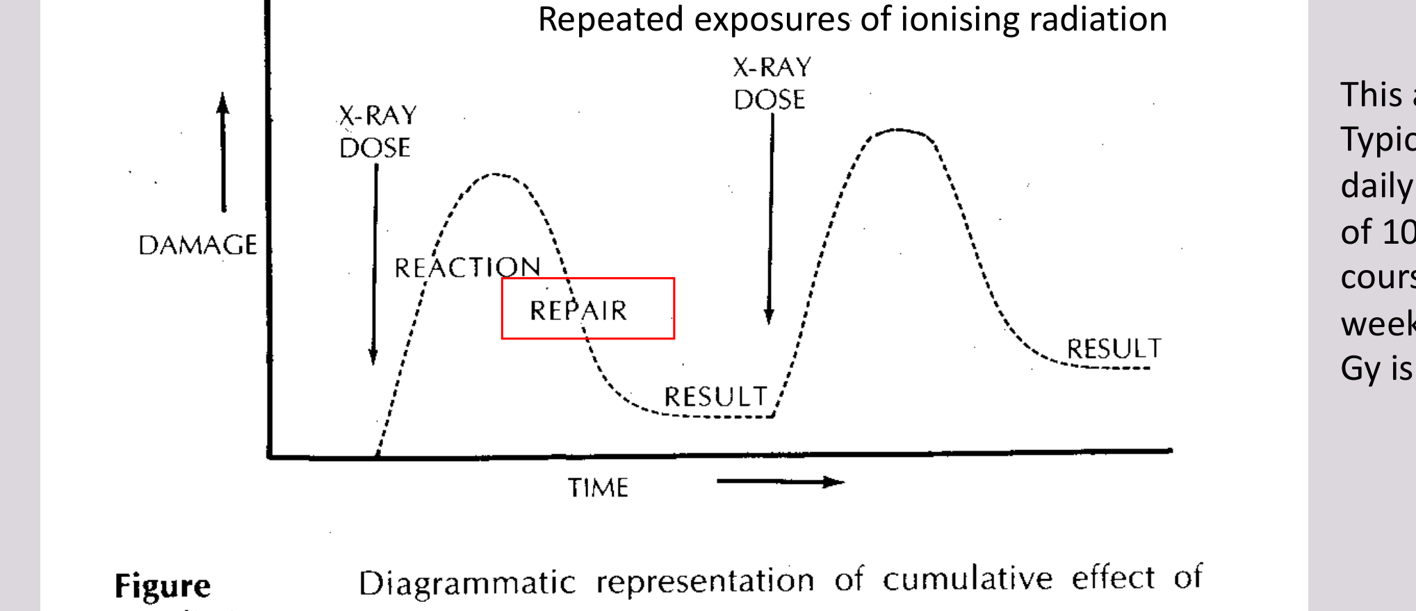
Cumulative Effect of X-ray61
There is evidence that dose accumulated over a long period carries less risk than the same dose received over a short period.
Diagrammatic representation of cumulative effect of x-radiation
- Repeated exposures of ionising radiation
- Fast (Reaction)
- X-RAY DOSE
- Failure
- DAMAGE
- TIME
- Slower effective rate
- Damage accumulation
This applies to radiotherapy. Typically, 2 Gy is delivered daily for a weekly exposure of 10 Gy. The radiotherapy course continues for 6 to 7 weeks until a total of 60 to 70 Gy is administered.
Damaging effect of radiation at different doses. The descending curve shows that survival decreases as the dose increases. The rising curve shows that survival increases as time elapsed after exposure increases. This indicates that cells have time to repair themselves if given enough time.
The diagram illustrates that the effect of radiation on a cell is not immediate but depends on both the size of the dose and the time interval between doses. This suggests that repeated exposures may be less harmful than a single large exposure because cells have time to repair themselves.
The graph shows that if you split the total dose into smaller fractions given at intervals long enough for repair mechanisms to act, then the overall damage will be less than if all the dose were received at once. Hence the concept of the ‘cellular survival curve’.
This approach forms the basis of fractionated radiotherapy where full therapeutic effect is achieved using multiple daily treatments of small doses rather than one large dose of the same total amount. It is based upon the principle that biologically effective dose decreases with increasing separation of treatment sessions within the cellular recovery period of the organism (usually around 24 hours).
Radiation Protection Principles
The ALARA Principle
ALARA / ALARP / ALADA62
- As
- Low
- As
- Reasonably
- Achievable
ALWAYS!
Principle of radioprotection stating that whenever ionizing radiation has to be applied to humans, animals or materials exposure should be as low as reasonably or diagnostically achievable / practicable / acceptable. It is fundamental to the principles of radiation protection.
Minimising Exposure for Patients and Staff
Minimising Exposure for Patient63
- Only take radiographs when necessary
- Adequate filtration
- Adequate collimation
- Constant potential rectification
- Lead apron and thyroid shield *
- Fastest film or intensifying screens (in Analogue system)
- Use digital imaging
- Minimize technical errors
- Well-maintained equipment
Minimising Exposure for Dental Staff64
- Avoid the primary beam
- Increase Distance (inverse square law), at least 2m
- Shielding
- Position
- Most of the measures already mentioned to protect the patient
Inverse Square Law65
source strength S sphere area 4πr² intensity at surface of sphere S / (4πr²) = I
The energy twice as far from the source is spread over four times the area, hence one-fourth the intensity. 2r → I/4 3r → I/9
the intensity of an X-ray beam at a given point is inversely proportional to the square of the distance from the source of radiation.
Clinical Responsibilities and Risk Communication66
 |  |
Dentist’s Responsibilities67
- Patient Care
- Determination of the clinical NEED to take X-ray
- Radiography and dose determination
- Processing technique (analogue films)
- Maintenance of radiographic records
- Maintenance of radiographic equipment
- Interpretation & Diagnosis (get help from DMF Radiologist)
- All 3D imaging legally requires radiologist’s report in WA
Irradiating Pregnant Women68
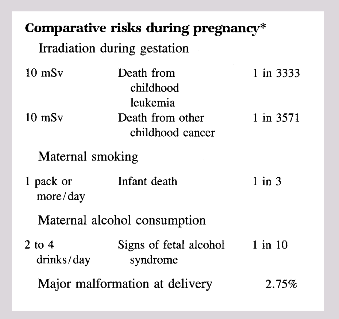
Probability of Child’s Death from Diagnostic X-ray (dental or medical) VS. Probability of Child’s Death from Maternal Smoking
→ 10 x annual patient radiation dose <<<< 1 cig/day maternal smoking
Comparative risks during pregnancy*
Irradiation during gestation
| Dose | Outcome | Probability |
|---|---|---|
| 10 mSv | Death from childhood leukemia | 1 in 3333 |
| 10 mSv | Death from other childhood cancer | 1 in 3571 |
Maternal smoking
| Dose | Outcome | Probability |
|---|---|---|
| 1 pack or more/day | Infant death | 1 in 3 |
Maternal alcohol consumption
| Dose | Outcome | Probability |
|---|---|---|
| 2 to 4 drinks/day | Signs of fetal alcohol syndrome | 1 in 10 |
| Major malformation at delivery | 2.75% |
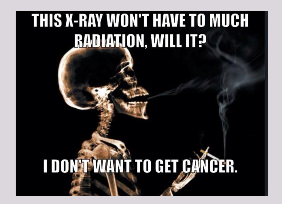
“This X-ray won’t have to much radiation, will it?” “I don’t want to get cancer.”
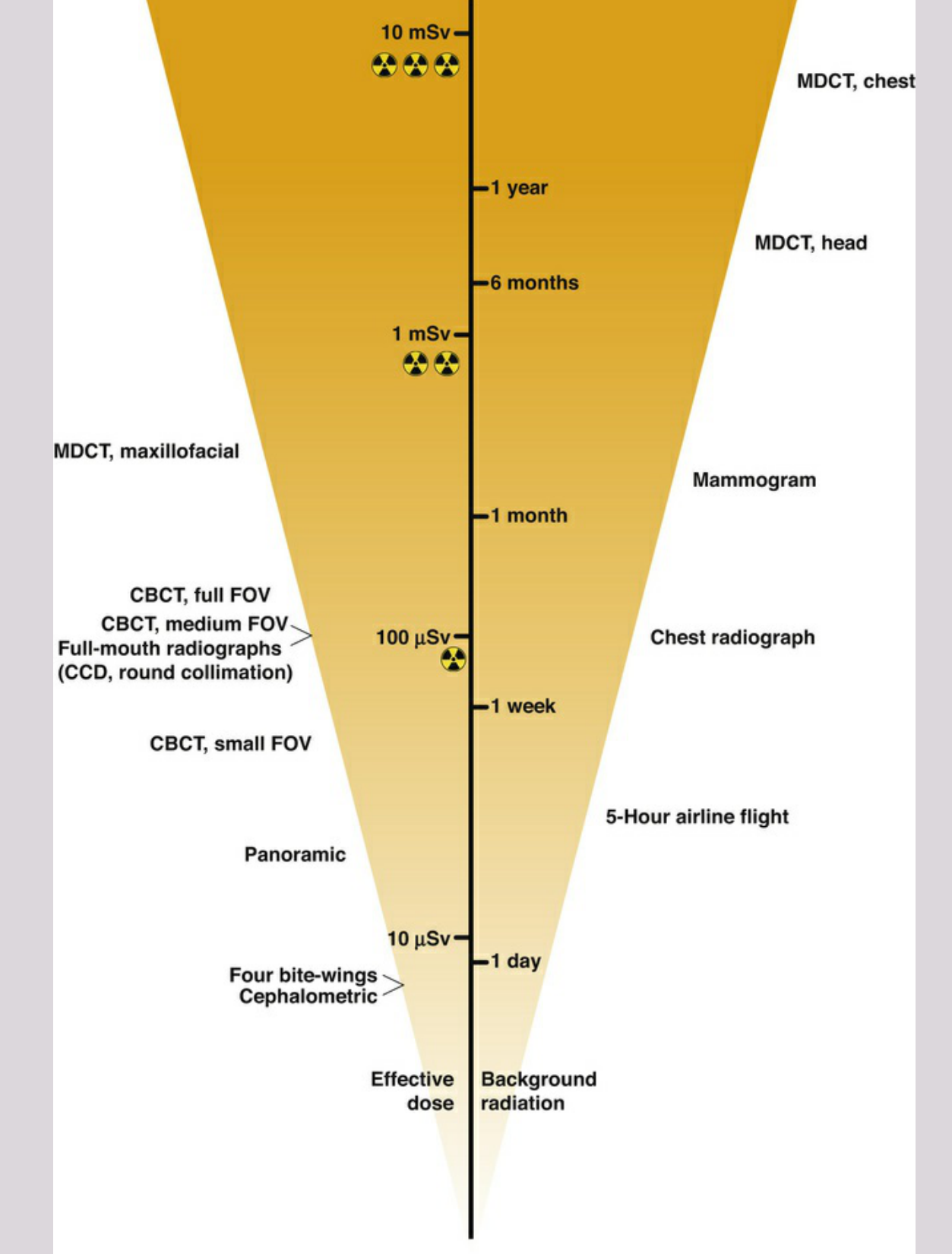
- 10 mSv: MDCT, chest, 1 year
- MDCT, head, 6 months
- Mammogram, 1 month
- CBCT, full FOV; CBCT, medium FOV; Full-mouth radiographs (CCD, round collimation)
- 100 µSv: Chest radiograph, 1 week; CBCT, small FOV; 5-Hour airline flight; Panoramic
- 10 µSv: 1 day; Four bite-wings; Cephalometric
Effective dose Background radiation
Footnotes
-
Original PDF page 1: 1.Radiation Physics and Safety(1), p.1 ↩
-
Original PDF page 2: 1.Radiation Physics and Safety(1), p.2 ↩
-
Original PDF page 3: 1.Radiation Physics and Safety(1), p.3 ↩
-
Original PDF page 4: 1.Radiation Physics and Safety(1), p.4 ↩
-
Original PDF page 5: 1.Radiation Physics and Safety(1), p.5 ↩
-
Original PDF page 6: 1.Radiation Physics and Safety(1), p.6 ↩
-
Original PDF page 7: 1.Radiation Physics and Safety(1), p.7 ↩
-
Original PDF page 8: 1.Radiation Physics and Safety(1), p.8 ↩
-
Original PDF page 9: 1.Radiation Physics and Safety(1), p.9 ↩
-
Original PDF page 10: 1.Radiation Physics and Safety(1), p.10 ↩
-
Original PDF page 11: 1.Radiation Physics and Safety(1), p.11 ↩
-
Original PDF page 12: 1.Radiation Physics and Safety(1), p.12 ↩
-
Original PDF page 13: 1.Radiation Physics and Safety(1), p.13 ↩
-
Original PDF page 14: 1.Radiation Physics and Safety(1), p.14 ↩
-
Original PDF page 15: 1.Radiation Physics and Safety(1), p.15 ↩
-
Original PDF page 16: 1.Radiation Physics and Safety(1), p.16 ↩
-
Original PDF page 17: 1.Radiation Physics and Safety(1), p.17 ↩
-
Original PDF page 18: 1.Radiation Physics and Safety(1), p.18 ↩
-
Original PDF page 19: 1.Radiation Physics and Safety(1), p.19 ↩
-
Original PDF page 20: 1.Radiation Physics and Safety(1), p.20 ↩
-
Original PDF page 21: 1.Radiation Physics and Safety(1), p.21 ↩
-
Original PDF page 22: 1.Radiation Physics and Safety(1), p.22 ↩
-
Original PDF page 24: 1.Radiation Physics and Safety(1), p.24 ↩
-
Original PDF page 26: 1.Radiation Physics and Safety(1), p.26 ↩
-
Original PDF page 27: 1.Radiation Physics and Safety(1), p.27 ↩
-
Original PDF page 31: 1.Radiation Physics and Safety(1), p.31 ↩
-
Original PDF page 29: 1.Radiation Physics and Safety(1), p.29 ↩
-
Original PDF page 30: 1.Radiation Physics and Safety(1), p.30 ↩
-
Original PDF page 32: 1.Radiation Physics and Safety(1), p.32 ↩
-
Original PDF page 33: 1.Radiation Physics and Safety(1), p.33 ↩
-
Original PDF page 34: 1.Radiation Physics and Safety(1), p.34 ↩
-
Original PDF page 35: 1.Radiation Physics and Safety(1), p.35 ↩
-
Original PDF page 36: 1.Radiation Physics and Safety(1), p.36 ↩
-
Original PDF page 37: 1.Radiation Physics and Safety(1), p.37 ↩
-
Original PDF page 38: 1.Radiation Physics and Safety(1), p.38 ↩
-
Original PDF page 39: 1.Radiation Physics and Safety(1), p.39 ↩
-
Original PDF page 40: 1.Radiation Physics and Safety(1), p.40 ↩
-
Original PDF page 41: 1.Radiation Physics and Safety(1), p.41 ↩
-
Original PDF page 42: 1.Radiation Physics and Safety(1), p.42 ↩
-
Original PDF page 44: 1.Radiation Physics and Safety(1), p.44 ↩
-
Original PDF page 45: 1.Radiation Physics and Safety(1), p.45 ↩
-
Original PDF page 43: 1.Radiation Physics and Safety(1), p.43 ↩
-
Original PDF page 46: 1.Radiation Physics and Safety(1), p.46 ↩
-
Original PDF page 48: 1.Radiation Physics and Safety(1), p.48 ↩
-
Original PDF page 49: 1.Radiation Physics and Safety(1), p.49 ↩
-
Original PDF page 50: 1.Radiation Physics and Safety(1), p.50 ↩
-
Original PDF page 51: 1.Radiation Physics and Safety(1), p.51 ↩
-
Original PDF page 52: 1.Radiation Physics and Safety(1), p.52 ↩
-
Original PDF page 53: 1.Radiation Physics and Safety(1), p.53 ↩
-
Original PDF page 54: 1.Radiation Physics and Safety(1), p.54 ↩
-
Original PDF page 55: 1.Radiation Physics and Safety(1), p.55 ↩
-
Original PDF page 56: 1.Radiation Physics and Safety(1), p.56 ↩
-
Original PDF page 57: 1.Radiation Physics and Safety(1), p.57 ↩
-
Original PDF page 58: 1.Radiation Physics and Safety(1), p.58 ↩
-
Original PDF page 59: 1.Radiation Physics and Safety(1), p.59 ↩
-
Original PDF page 60: 1.Radiation Physics and Safety(1), p.60 ↩
-
Original PDF page 61: 1.Radiation Physics and Safety(1), p.61 ↩
-
Original PDF page 62: 1.Radiation Physics and Safety(1), p.62 ↩
-
Original PDF page 63: 1.Radiation Physics and Safety(1), p.63 ↩
-
Original PDF page 64: 1.Radiation Physics and Safety(1), p.64 ↩
-
Original PDF page 65: 1.Radiation Physics and Safety(1), p.65 ↩
-
Original PDF page 66: 1.Radiation Physics and Safety(1), p.66 ↩
-
Original PDF page 67: 1.Radiation Physics and Safety(1), p.67 ↩
-
Original PDF page 68: 1.Radiation Physics and Safety(1), p.68 ↩
-
Original PDF page 69: 1.Radiation Physics and Safety(1), p.69 ↩
-
Original PDF page 72: 1.Radiation Physics and Safety(1), p.72 ↩
-
Original PDF page 70: 1.Radiation Physics and Safety(1), p.70 ↩
-
Original PDF page 71: 1.Radiation Physics and Safety(1), p.71 ↩