Computed Tomography: CT and CBCT1
Computed Tomography: CT & CBCT
Dr Dayea Oh
OMF Radiologist
 |  |
Learning Objectives2
- To understand the basic theory of computed tomography
- Understand when to order advanced imaging (CT, MRI, ultrasound, and nuclear medicine).
- What is Hounsfield Unit?
- What are the indications for Multislice CT?
- What are the indications for Cone Beam CT?
- What are the CBCT artefacts?
- What are the differences between Multislice CT and Cone Beam CT?
- Distinguish between the two primary types of CT used in the head and neck region: Multi-Slice CT (MSCT) and Cone Beam CT (CBCT).
Advanced Imaging Modalities in DMFR3
- Multi-slice / Multi-detector Computed Tomography (MSCT / MDCT)
- Cone Beam Computed Tomography (CBCT)
- Magnetic Resonance Imaging (MRI)
- Ultrasound
- Nuclear Medicine Imaging (NMI)
Computed Tomography Fundamentals456
Computed Tomography, CT
-
Invented in 1971 by Sir Godfrey Hounsfield
- Sir Godfrey Hounsfield received the Nobel Prize in 1979 for this invention.
- First CT scan was Brain CT
-
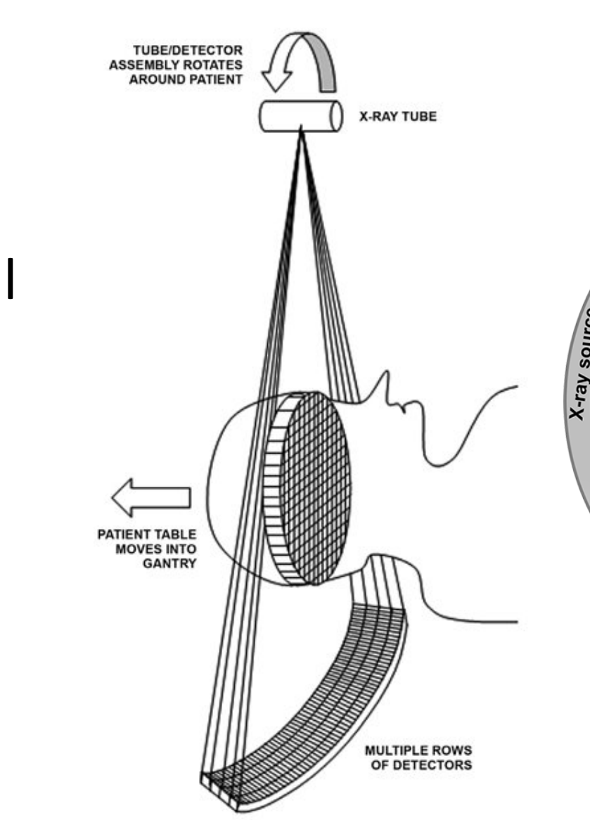
Fan-shaped, continuous, rotational x-ray beam
-
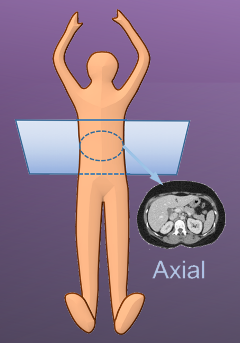
“Slices” of cross-sectional / transverse / axial im
-
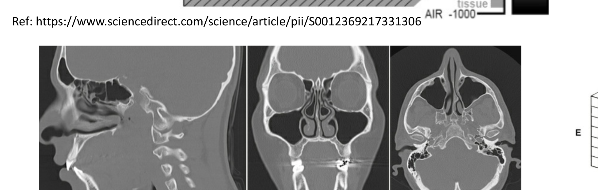
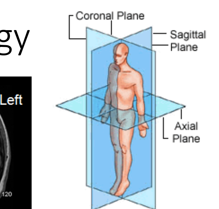
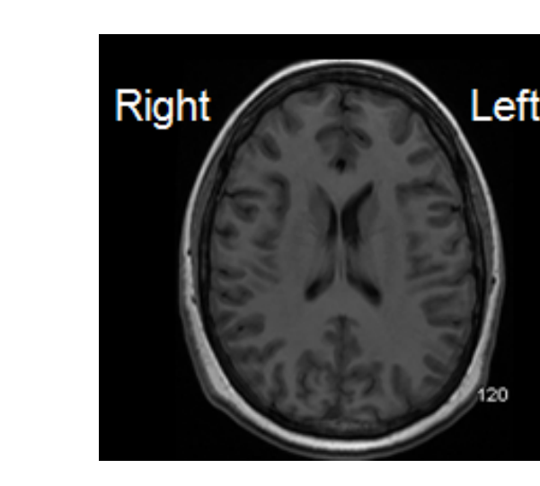
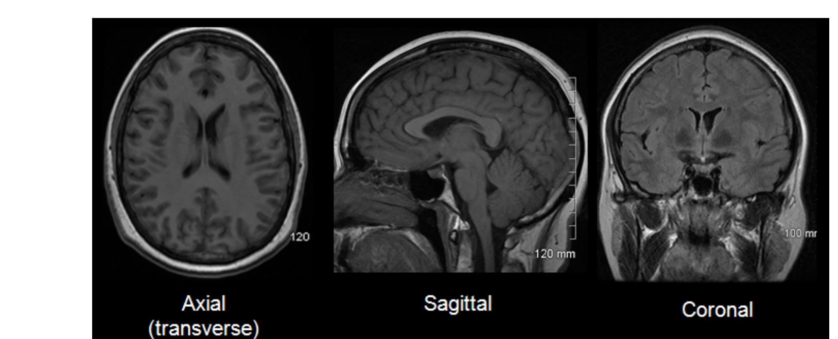
Axial (Transverse) Plane: Horizontal plane dividing the body into superior and inferior parts.
-
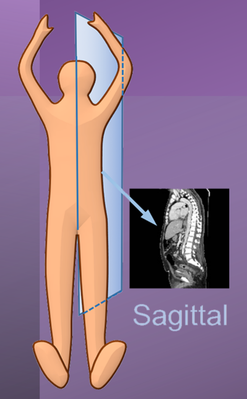
Sagittal Plane: Vertical plane dividing the body into right and left halves.
-
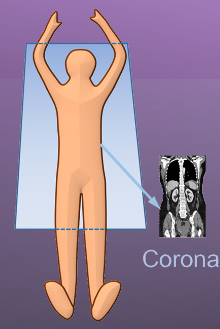
Coronal Plane: Vertical plane dividing the body into anterior and posterior parts. ages
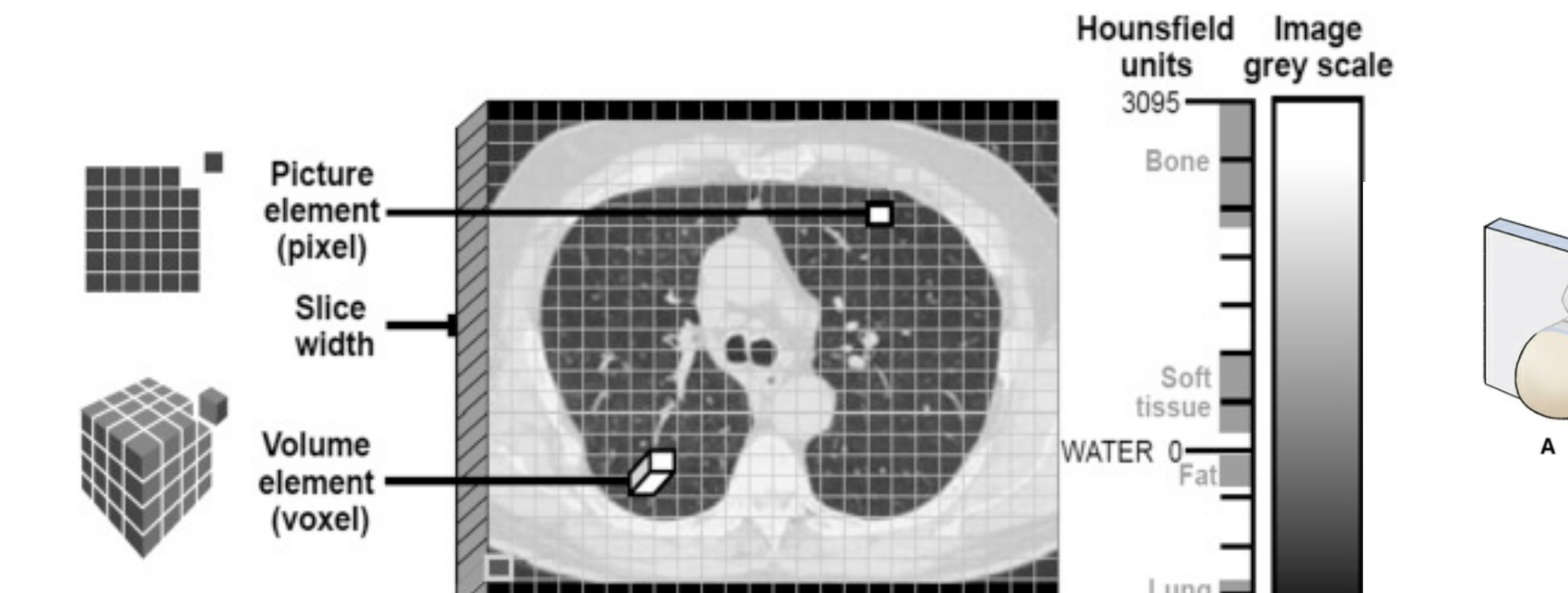
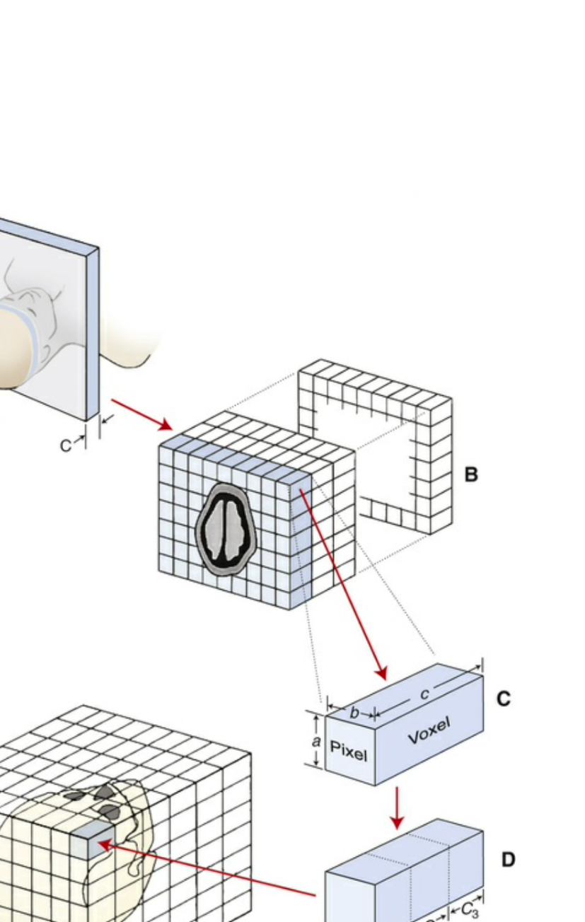
- Hundreds to thousands of acquired slices are later reconstructed (= digitally stacked together) to form volumetric imaging
-
Voxels: Three-dimensional volumetric pixels containing photon attenuation data.
-
Attenuation: Denser tissue results in greater attenuation and a brighter image.
-
Hounsfield Units (HU): A scale from -1000 (air, darkest) to approximately 3000 (compact bone, brightest).
Evolution of CT Speed
The first brain CT took five minutes to scan and 2.5 hours to reconstruct. Modern CTs can scan a whole head in less than a second with reconstruction taking only a few seconds.
<TUBE/DETECTOR ASSEMBLY ROTATES AROUND PATIENT>
 |  |  |
 |  |  |
 |  |
Three-Dimensional Imaging Orientation and Terminology7
3D Imaging Orientation - Terminology
- Anterior
- Posterior
- Superior
- Inferior
- Medial
- Lateral
- Superficial
- Deep
- Ipsilateral
- Contralateral
- Note: In radiology, the viewer’s right is the patient’s left.
Right
Left
MRI images
Axial (transverse) Sagittal Coronal
| Coronal | Sagittal |
|---|---|
| Plane | |
| Body | |
| Right | |
| Plane | Left |
| Sagittal | |
| Plane | |
| Axial | |
| Body | |
| Plane |
 |  |
 |
Modern Multislice CT Technology8
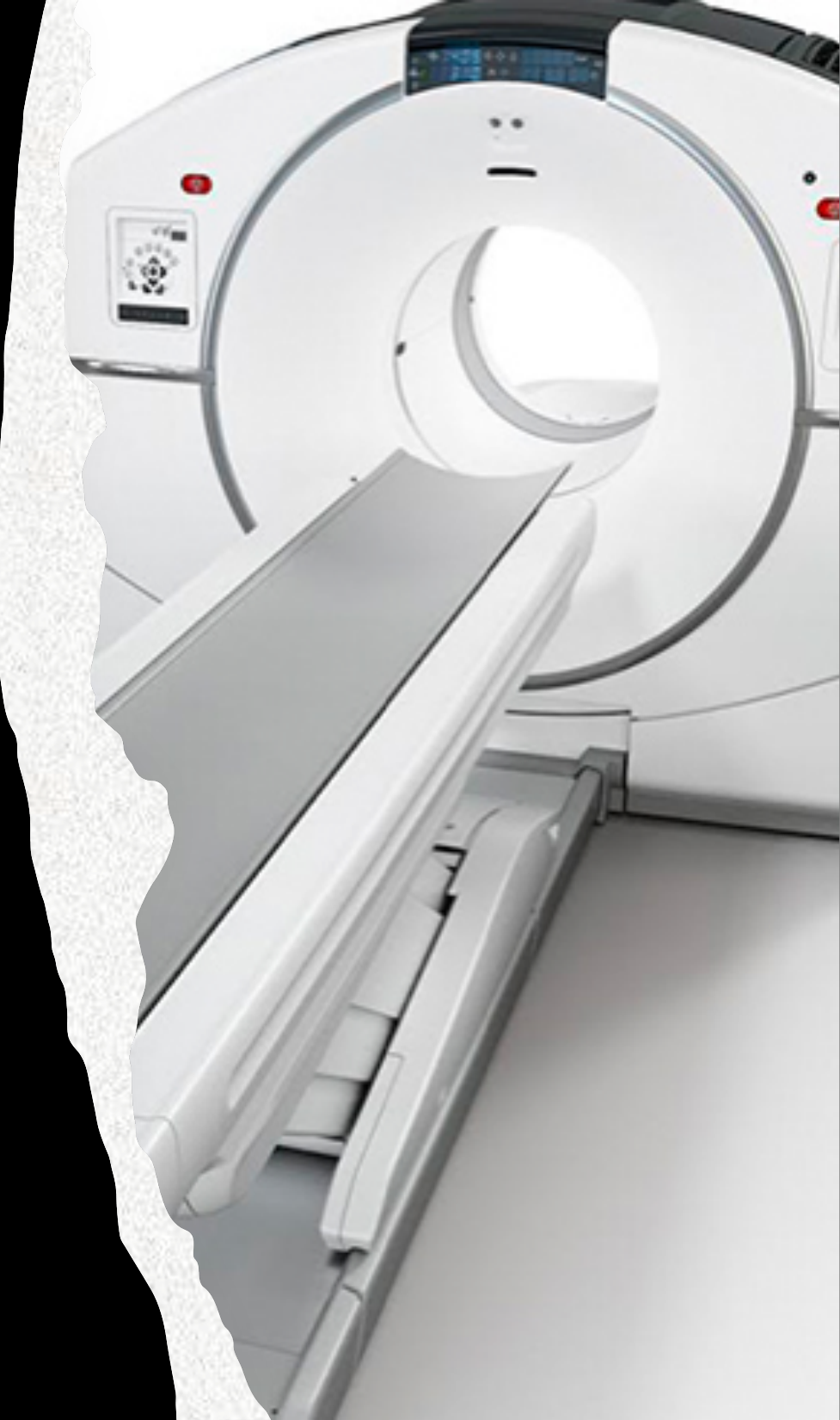
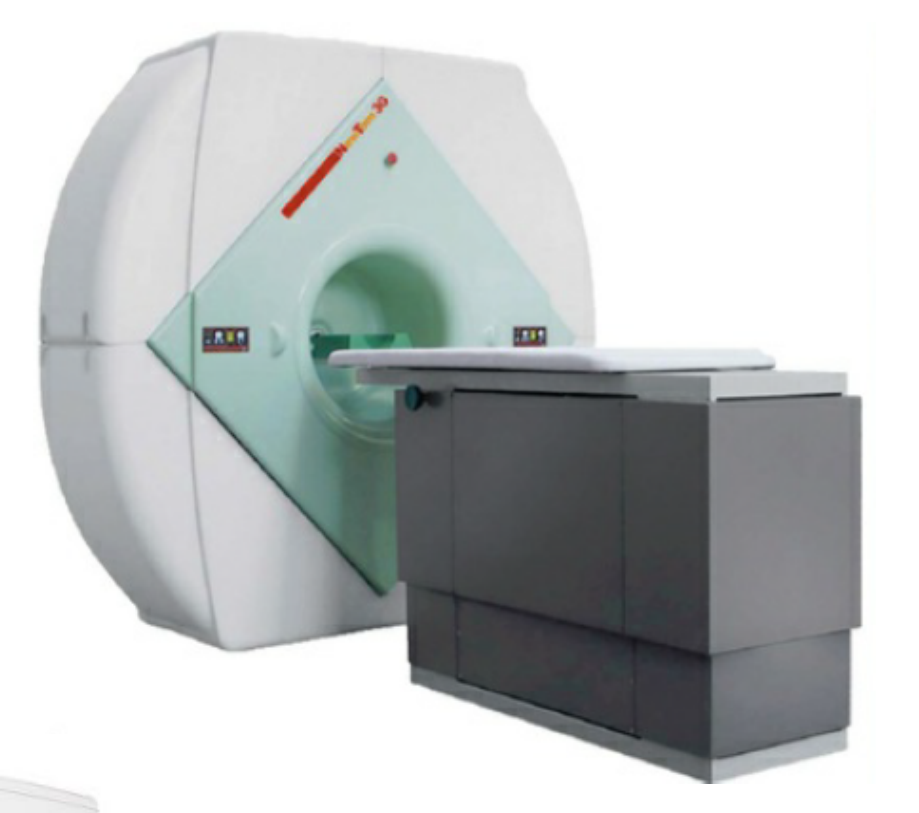
Modern CT Machine
- Helical CT
- 3rd generation
- Multi-detector CT aka Multislice CT
- Very fast scan time (~ 1 second to scan jaws)
- The extreme speed makes it ideal for emergency trauma and cardiac assessment.
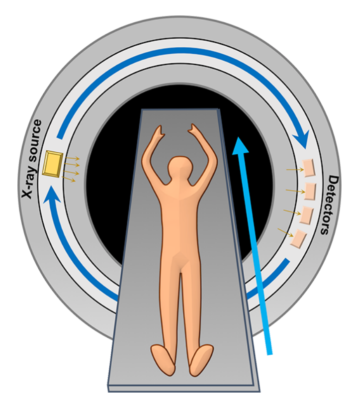
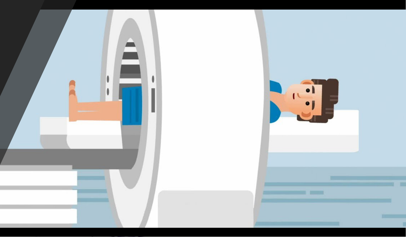
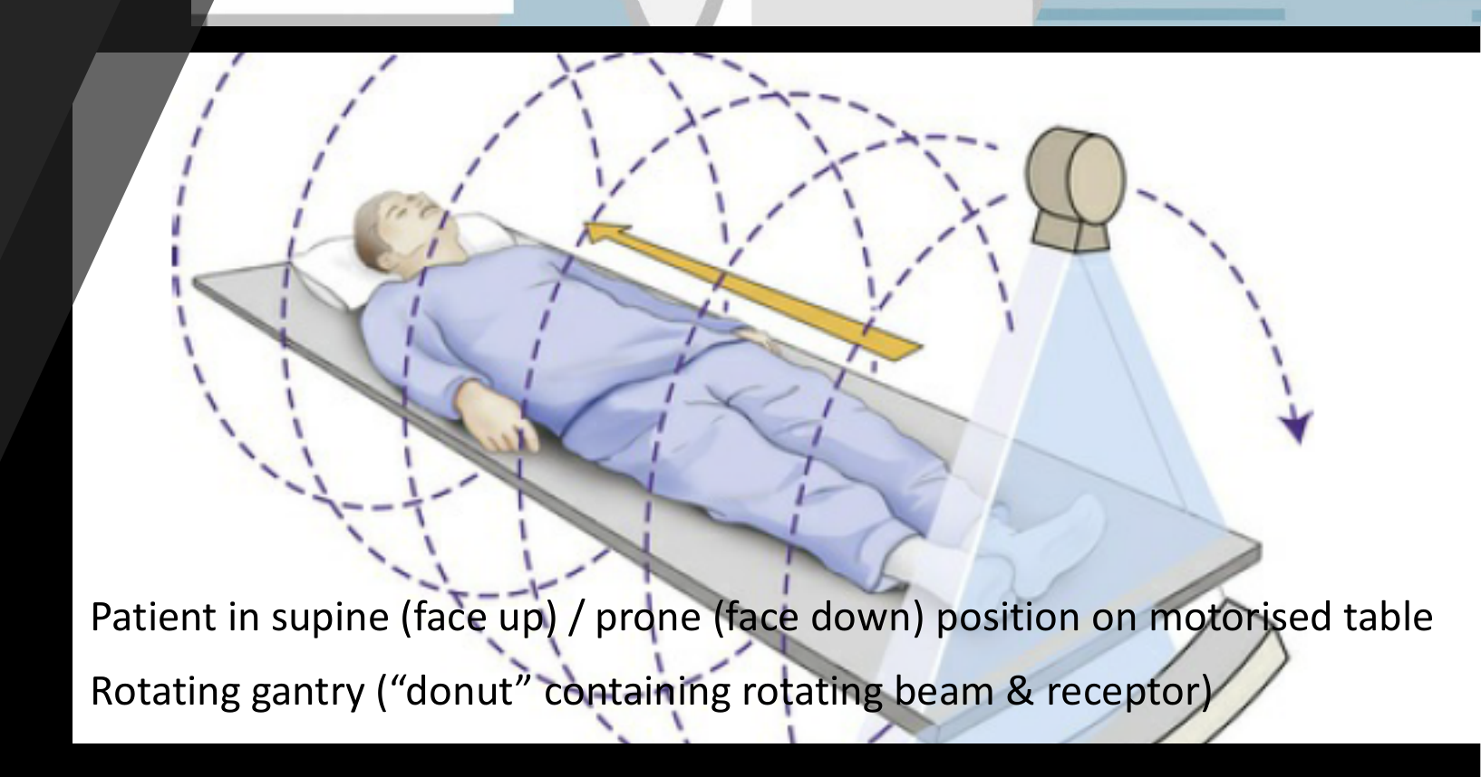
- X-ray tube & detectors continuously revolve around the patient while the patient table moves through the gantry
- Continuous helix of data is acquired as the x-ray beam moves down the patient
- Patient in supine (face up) / prone (face down) position on motorised table
Rotating gantry (“donut” containing rotating beam & receptor)
 |  |
Head and Neck CT Applications9
CT Applications – Head and Neck
- Trauma
- Pathology
- Jaw pathology (cysts, tumours, malignancies, etc.)
- Sinus pathology
- Salivary gland pathology
- Oral cancer
- ON
- Non-specific dental pain
- Rule out neuropathic pain
- Dentistry (low dose protocol)
- Implant dentistry - Used by surgeons to measure bone volume in 3D and assess bone density via Hounsfield units.
- Other:
- Special needs dentistry
Not used in General Dentistry
Clinical CT Workflow10
CT Workflow
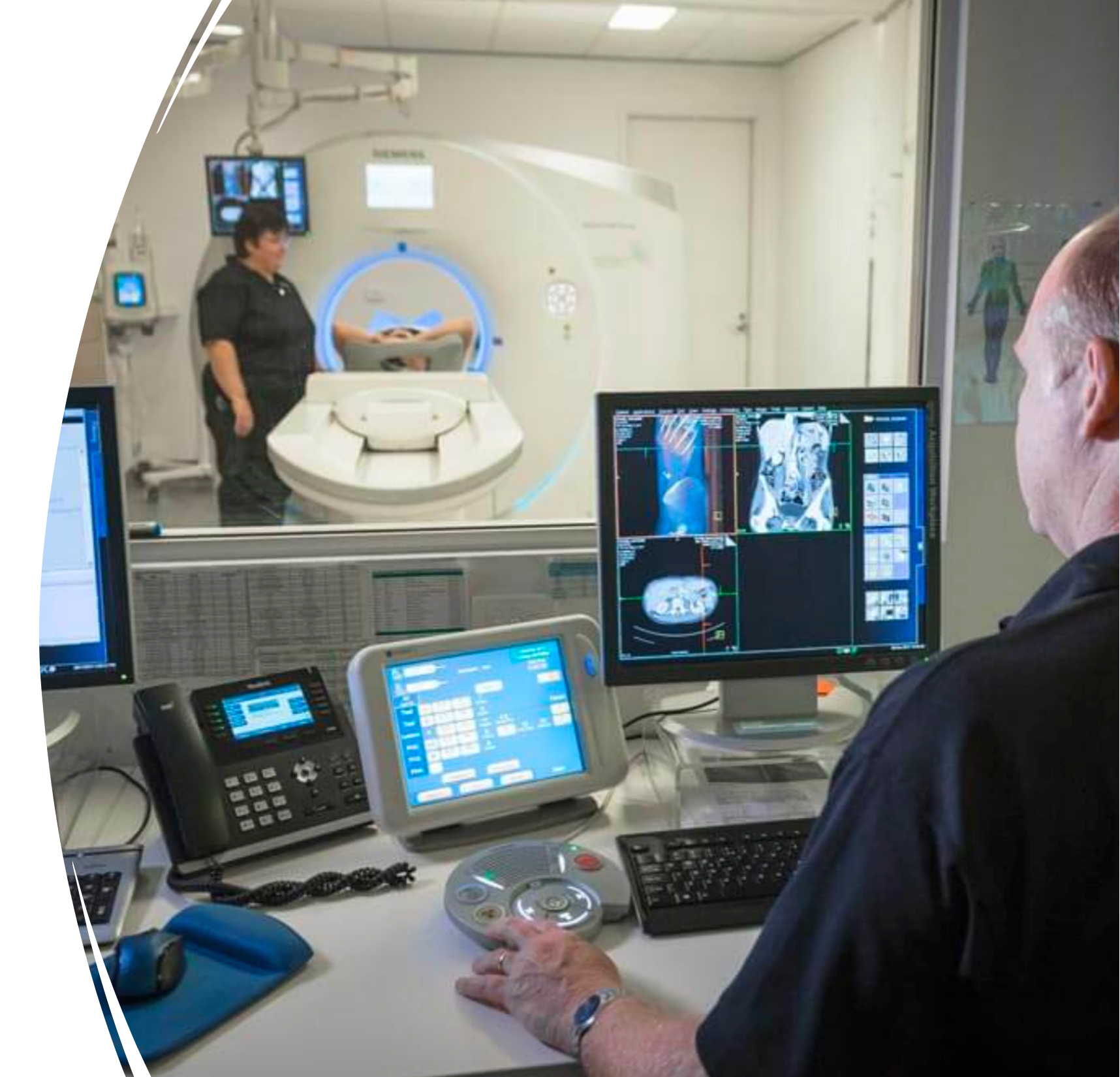
- Referral
- Must include patient details, area of focus, and clinical history (e.g., “trauma to right mandible”).
- Protocol
- Radiographer and radiologist select the protocol based on clinical need and radiation safety.
- Acquisition (scan)
- Data preprocessing
- Reconstruction
- Interpretation
- Report
Cone Beam Computed Tomography11
Cone Beam CT
CBCT Technical Principles and Scanning Methods12
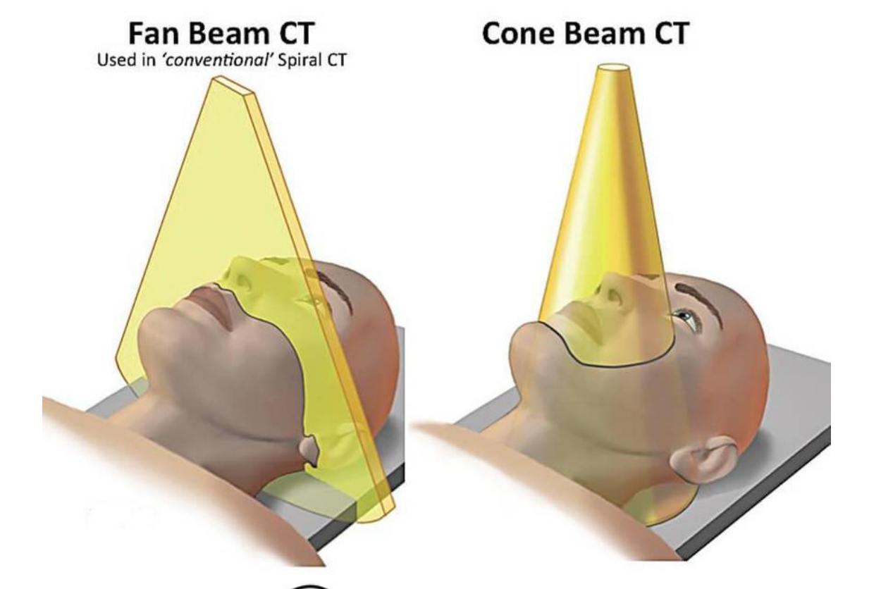
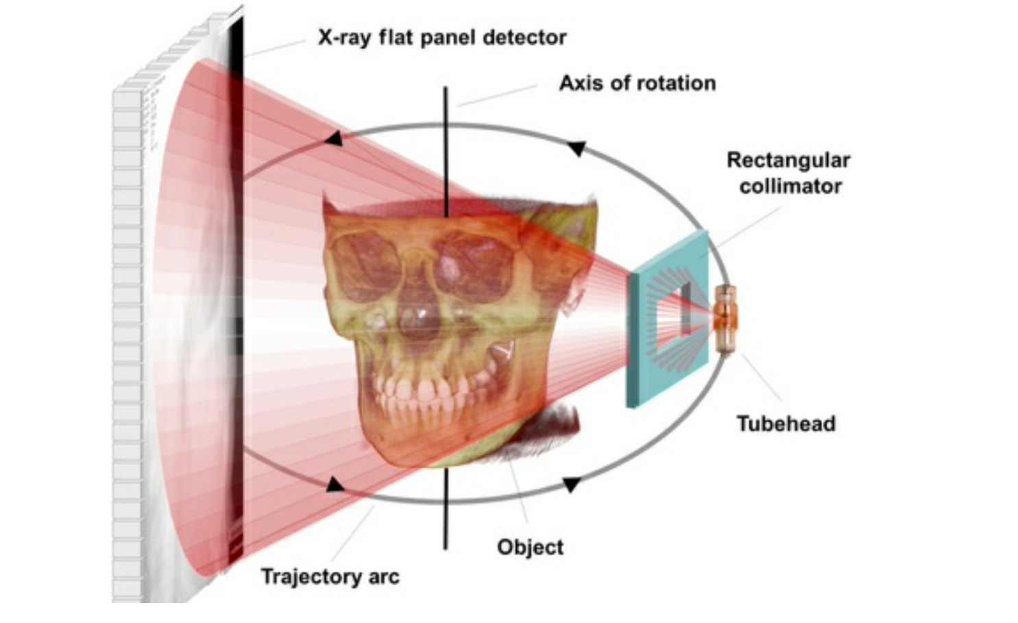
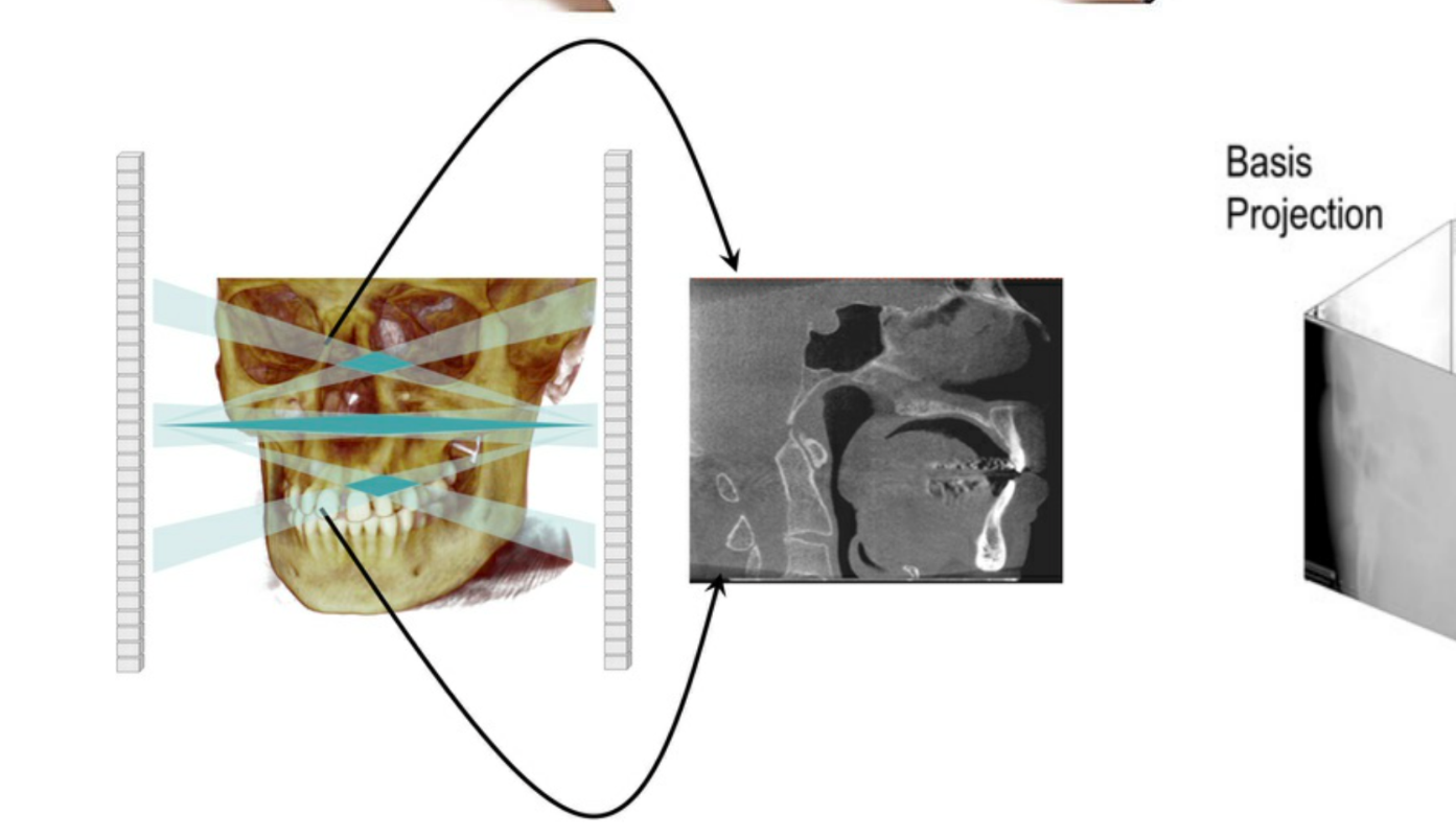
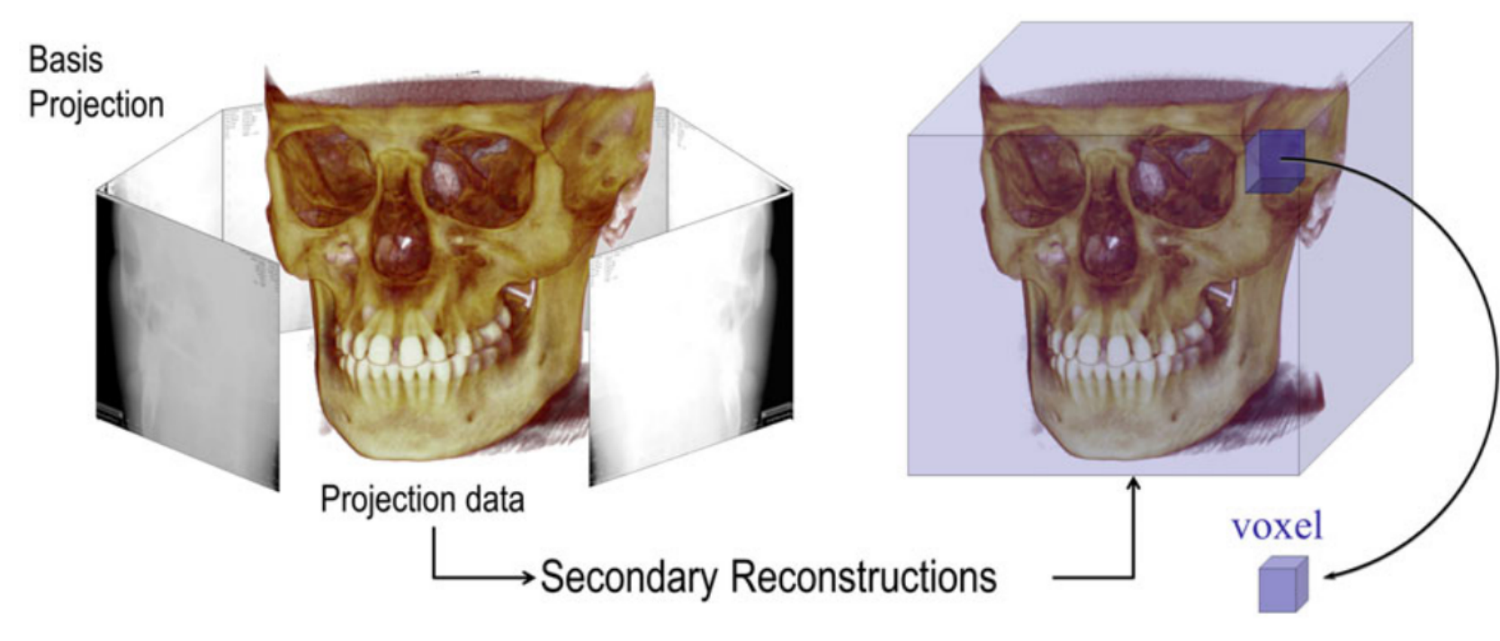
Figure describing Fan Beam, Cone Beam, and Reconstruction CT scanning methods
- Fan Beam CT: Used in ‘conventional’ Spiral CT
- Cone Beam CT
- Rectangular collimator
- X-ray flat panel detector
- Axis of rotation
- Trajectory arc
- Object
- Tubehead
- Basis Projection
- Projection data
- Secondary Reconstructions
- voxel
Basis Images and Attenuation
- CBCT basis images look like conventional skull views (e.g., PA or lateral skull views) rather than MSCT slices.
- Voxels do not accurately represent photon attenuation because the cone beam is heterogeneous and prone to scattering.
 |  |
 |  |
CBCT Machine Design and Resolution1314
- Early
- Similar design to MDCT
- Supine
- Fixed table (not mobile)
- Modern CBCT
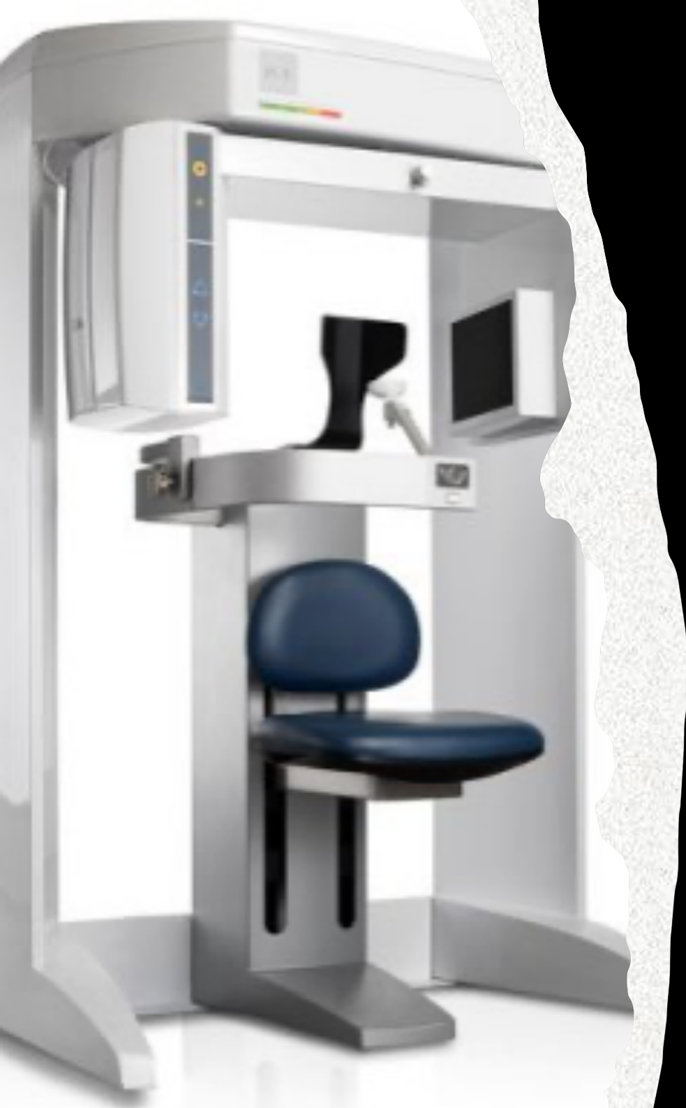
- Compact design
- Some are similar to PR units
- Stand-up or Seated
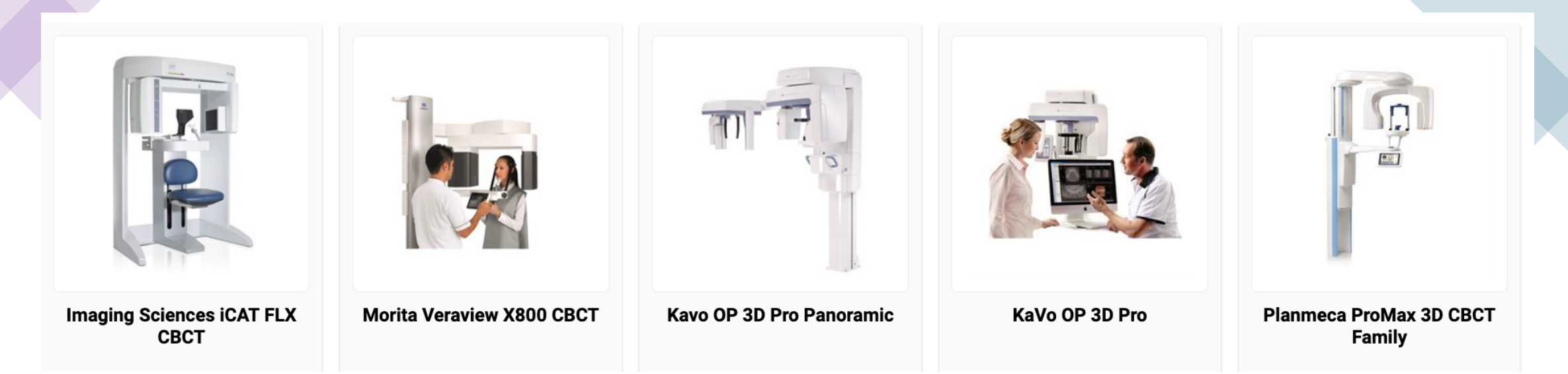
Example CBCT Machines
- Imaging Sciences iCAT FLX CBCT
- Morita Veraview X800 CBCT
- Kavo OP 3D Pro Panoramic
- KaVo OP 3D Pro
- Planmeca ProMax 3D CBCT Family
Spatial Resolution & Voxel Size
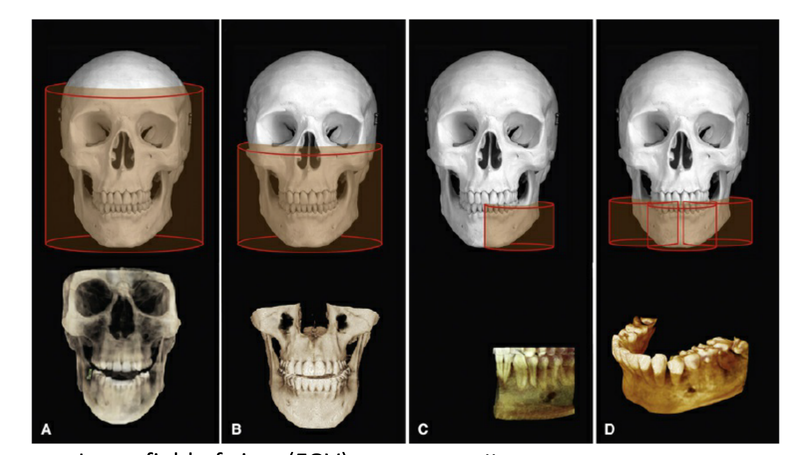
- Large field of view (FOV)
- Small FOV
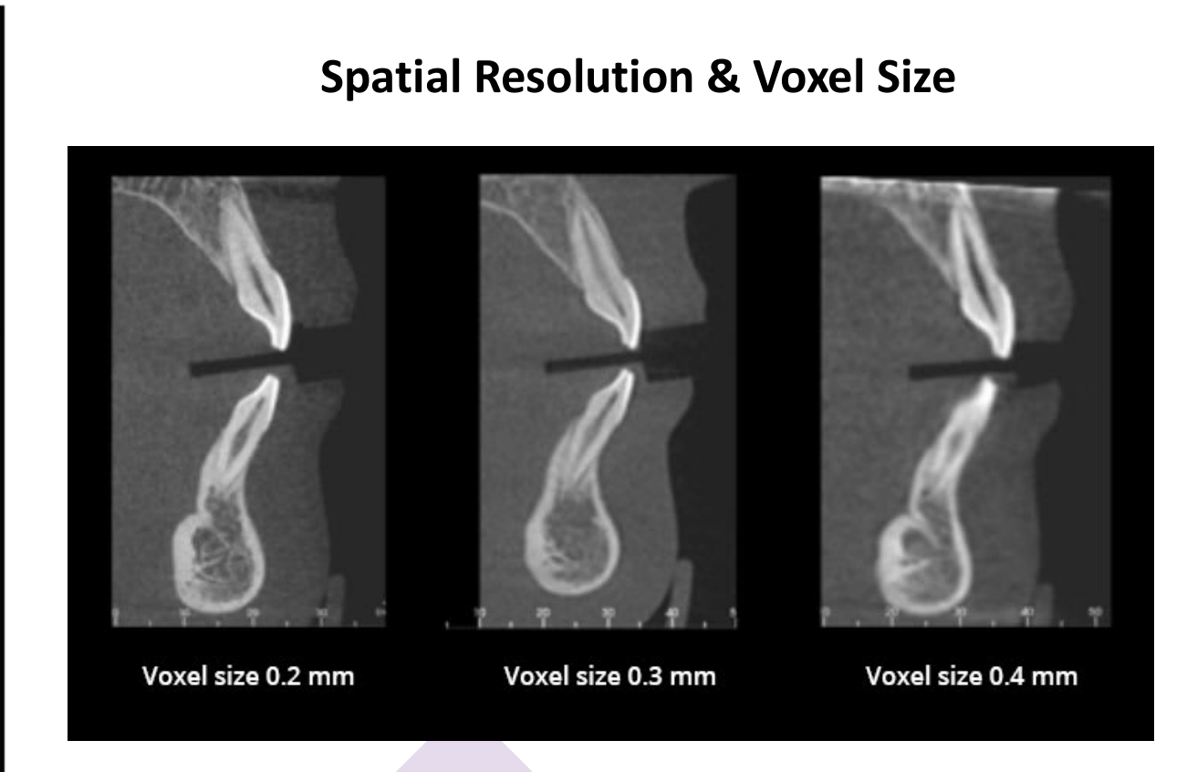
- Voxel size 0.2 mm
- Voxel size 0.3 mm
- Voxel size 0.4 mm
- Small voxels (0.07 mm to 0.1 mm) provide higher detail but are only available in small Fields of View (FOV).
- Endodontics requires a voxel size of 0.1 mm or less to locate calcified canals.
 | 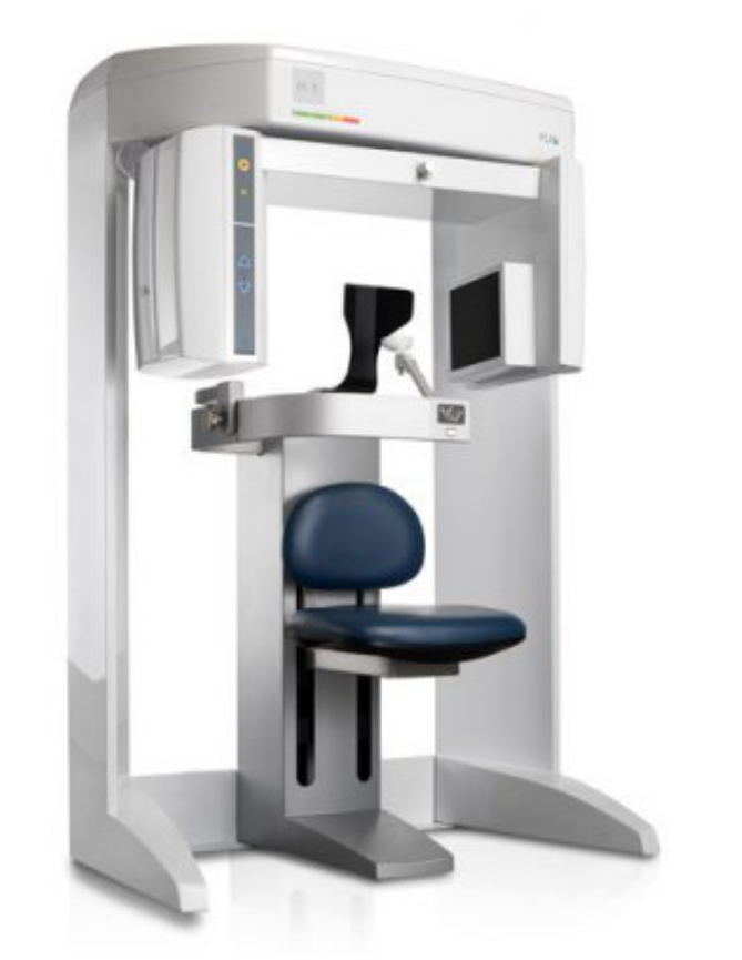 | 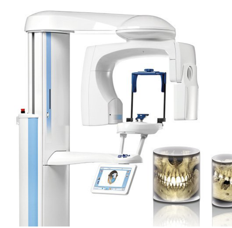 |
 |  |  |
Clinical Indications for CBCT in Dentistry15
- Dental Trauma
- Root fractures
- Third molar assessment
- Supernumerary teeth
- Impacted Canines
- Implant assessment
- Periodontal assessment
- 3D bone loss
- Complex endodontic therapy
- High res for root canal morphology
- Root resorption
- Orthodontic assessment
- Orthognathic surgical planning
- Digital dentistry
- 3D printing eg. surgical guides
- TM Joint (limited to osseous)
- Pathology (limited to osseous)
Soft Tissue Limitation
CBCT is not used for tumors or soft tissue pathology as the nature of the cone beam prevents clear demonstration of soft tissues.
Radiation Safety and Effective Dose
Effective Radiation Dose16
- Background at sea level: 1.5mSv / year in Australia
- 1 PA is approximately 0.004 mSv (1 day of background radiation)
- 1 OPG: 0.008 – 0.01 mSv (2-3 days of background radiation)
- 1 Lat Ceph: ~0.005 mSv
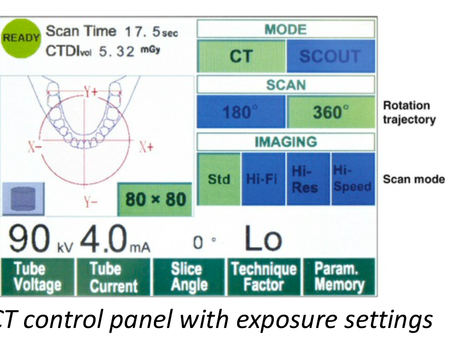
- CBCT dose varies and largely depends on FOV, voxel size, mA, kVp, rotation trajectory, etc.
- iCAT large FOV (maxillofacial region): ~0.07 mSv (2-3 weeks of background radiation)
- Large FOV (e.g., i-CAT) dose can range between 0.1 - 0.2 mSv.
- Planmeca 3D small FOV: ~0.03mSv (1 week of background radiation)
- Note: the radiation dosage of high resolution, small FOV can be as high as standard large FOV
- Low dose MSCT dosage is comparable to CBCT dosage
- Standard MSCT is usually high dose (up to 1 mSv), but low-dose protocols can match CBCT levels.
CBCT Anatomical Interpretation17
CBCT Data Display
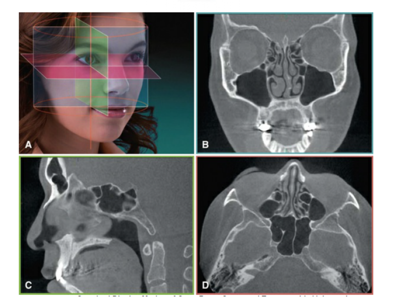
- Standard display (Orthogonal / Multiplanar view)
- Axial
- Coronal
- Sagittal
Planmeca Romexis
Axial CBCT Anatomy
Top Left Panel
- (Anatomical diagram labels) A, B, C, D, E
1. Frontal sinus 2. Frontal bone 3. Anterior cranial fossa 4. Squamous portion of temporal bone 5. Crista galli 6. Orbit 7. Greater wing of sphenoid bone 8. Nasal bone 9. Anterior ethmoid air cells 10. Perpendicular plate of ethmoid bone 11. Posterior ethmoid air cells 12. Optic canal 13. Superior orbital fissure 14. Nasal process of maxillary bone 15. Uncinate process 16. Sphenethmoid recess 17. Sphenoid sinus 18. Floor of sella turcica 19. Nasolacrimal duct 20. Superior turbinate 21. Inferior orbital fissure 22. Middle cranial fossa
Top Middle-Right Panel
- (Anatomical diagram labels) A, B, C, D, E
1. Nasal septum 2. Nasolacrimal duct 3. Maxillary sinus 4. Nasal turbinate 5. Zygomatic process of maxilla 6. Zygomaxillary suture 7. Zygomatic arch 8. Pterygopalatine fossa 9. Greater wing of sphenoid bone 10. Carotid canal 11. Petrous portion of temporal bone 12. Internal auditory canal 13. Infraorbital canal 14. Lateral wall of maxillary sinus 15. Pterygomaxillary fissure 16. Foramen ovale 17. Foramen spinosum 18. Glenoid fossa 19. Mandibular condyle 20. Carotid canal 21. Infraorbital foramen 22. Nasal cavity 23. Pterygoid plates 24. Nasopharyngeal airway 25. Occipital bone 26. Jugular foramen 27. Medial wall of maxillary sinus 28. Coronoid process 29. Pharyngeal wall 30. External auditory meatus 31. Mastoid process 32. Anterior nasal spine 33. Nasopalatine canal 34. Hard palate 35. Intermaxillary suture 36. Ramus of mandible 37. Anterior arch of atlas (C1) 38. Foramen magnum
Top Right Panel
- (Anatomical diagram labels) A, B, C, D, E
1. Incisive foramen 2. Tongue 3. Maxillary tuberosity 4. Soft palate 5. Oropharyngeal airway 6. Styloid process 7. Anterior arch of atlas (C1) 8. Odontoid process of C2 9. Ramus of mandible 10. Mandibular foramen 11. Inferior body of C2 12. Transverse foramen 13. Lamina of C2 14. Mandibular symphysis 15. Genial tubercles 16. Mental foramen 17. Epiglottis 18. Body of hyoid bone 19. Greater cornu of hyoid bone 20. C2-C3 neural foramen 21. Superior articular process of C3 22. Inferior articular process of C2
Coronal CBCT Anatomy
Anatomy Key 1
- Frontal bone
- Frontal sinus
- Nasal bone
- Maxillary bone
- Nasal septum
- Inferior nasal turbinate
- Ethmoid air cells
- Nasolacrimal duct
- Infraorbital canal
- Maxillary sinus
- Nasopalatine canal
- Incisive foramen
- Orbit
- Middle nasal turbinate
- Zygomatic process of the maxilla
- Mandible
- Crista galli of ethmoid bone
- Fronto-zygomatic suture
- Uncinate process
- Infraorbital ethmoid air cells (Haller cells)
- Ostium of maxillary sinus
- Infundibulum
- Hiatus semilunaris
- Frontal recess
- Ethmoid bulla
- Inferior meatus
Anatomy Key 2
- Ethmoid air cells
- Superior nasal turbinate
- Middle nasal turbinate
- Zygomatic arch
- Maxillary sinus
- Inferior nasal turbinate
- Hard palate (floor of nasal cavity)
- Sphenoid bone
- Inferior orbital fissure
- Perpendicular plate of ethmoid bone
- Coronoid process of mandible
- Maxillary tuberosity
- Inferior alveolar canal
- Sphenoid sinus
- Pterygopalatine fossa
- Lateral pterygoid plate
- Medial pterygoid plate
- Mandibular ramus
- Floor of sella turcica
- Anterior clinoid process
- Optic canal
- Foramen rotundum
- Pterygoid (vidian) canal
- Nasopharyngeal airway
- Squamous temporal bone
- Zygomatic process of temporal bone
- Sphenosquamousal suture
- Foramen ovale
- Palatine tonsils
- Hyoid bone
Anatomy Key 3
- Glenoid fossa
- Mandibular condyle
- Foramen spinosum
- Basiocciput
- Carotid canal
- Petro-occipital suture
- Styloid process
- Oropharyngeal airway
- Epiglottis
- Semicircular canal
- External auditory meatus
- Odontoid process of C2
- Ossicles of ear
- Occipital condyles
- Lateral mass of C1
- Mastoid air cells
- Internal auditory meatus
- Jugular foramen
- Jugular bulb
- Body of C2
- Body of C3
- Foramen magnum
- Mastoid process
- Occipito-mastoid suture
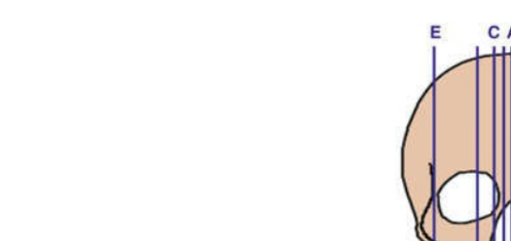
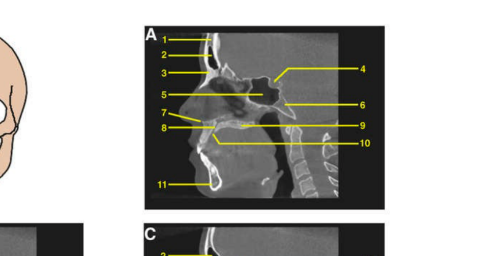
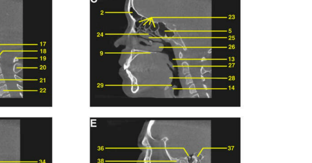
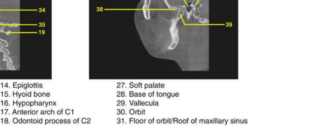
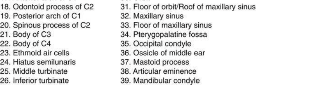
Sagittal CBCT Anatomy18
- Frontal bone
- Frontal sinus
- Nasal bone
- Sella turcica
- Sphenoid sinus
- Clivus
- Anterior nasal spine
- Nasopalatine canal
- Hard palate
- Incisive foramen
- Mandibular symphysis
- Nasopharyngeal airway
- Oropharyngeal airway
- Epiglottis
- Hyoid bone
- Hypopharynx
- Anterior arch of C1
- Odontoid process of C2
- Posterior arch of C1
- Spinous process of C2
- Body of C3
- Body of C4
- Ethmoid air cells
- Hiatus semilunaris
- Middle turbinate
- Inferior turbinate
- Soft palate
- Base of tongue
- Vallecula
- Orbit
- Floor of orbit / Roof of maxillary sinus
- Maxillary sinus
- Floor of maxillary sinus
- Pterygopalatine fossa
- Occipital condyle
- Ossicle of middle ear
- Mastoid process
- Articular eminence
- Mandibular condyle
 |  |  |
 |  |  |
Data Display and Secondary Reconstructions
CBCT Additional Display
Secondary Reconstruction
- Special algorithm required
- Reconstructed panoramic / curved oblique view
- Volume / 3D rendering
- Transaxial / Cross-sectional
- Essential for implant planning and identifying the mandibular canal (buccal-lingual relationship).
Standard (axial plane)
Specialized CBCT Display Modes
Other Additional Displays
- TMJ mode
- Mandibular Canal Tracing
- Implant placement simulator
- Airway mode
- Measures upper airway volume, though accuracy is limited.
- Note: Reconstructed Panoramic views are used for counting teeth but are not a substitute for OPG.
- Note: 3D/Volumetric Rendering is useful for localizing impacted teeth and patient education.
Interpretation Warning
Interpretation should only be done on Multi-Planar Reconstruction (MPR) views, as secondary reconstructions lose original data.
A: Cone beam CT slice
Limitations and Imaging Artefacts
Poor soft tissue contrast19
- Noise
- Patient related
- Movement
- Tremor
- Child
- Restorations
- High density restorations eg. amalgams, crowns, implants, etc.
- Movement
- Under-sampling
- Partial volume averaging
- Beam hardening
- Cone beam effect
- Detector related
- Ring artefact
- Dead pixel
- Noise: Caused by beam scattering and “quantum mottle.”
- Partial Volume Averaging: Voxel size is larger than the object, leading to an averaged grayscale that misrepresents true anatomy.
- Cone Beam Effect: Peripheral structures appear less defined.
- Ring/Dead Pixel Artefacts: Caused by faulty or uncalibrated detectors.
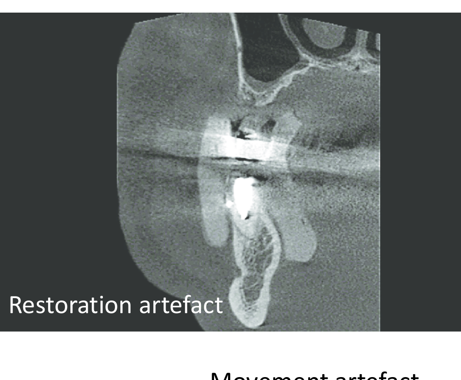 |  |
Restoration artefact
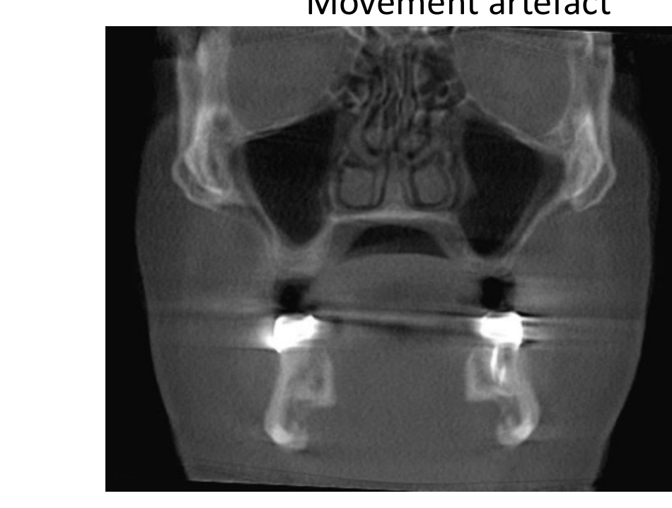
Movement artefact
- Results in blurry images or “double lines” of anatomy.
- If a patient cannot stay still (e.g., tremors), they should be referred for a faster MSCT scan.
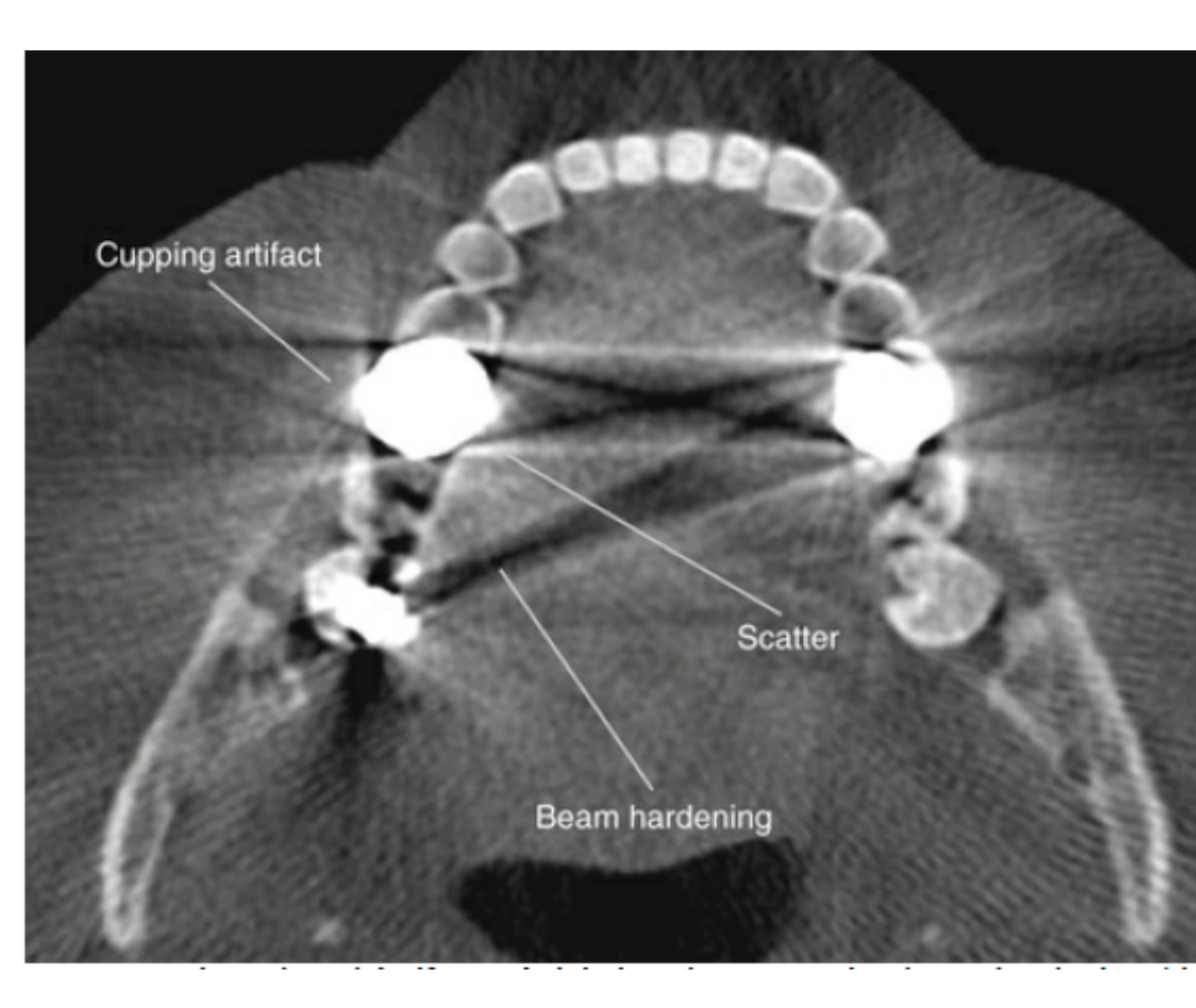
Most Pronounced Artefacts20
- Patient movement artefact
- CBCT takes up to 30 seconds to scan
- Restoration artefacts (or just dense object artefacts)
- Cupping artefact (shape distortion)
- Scatter/Streaking (white lines)
- Beam hardening
- Appears as black lines adjacent to scattering.
- Cupping: Distortion of the object’s shape.
- Scattering/Streaking: White lines at the periphery.
- Mitigation: Separate the jaws during the scan to prevent overlapping artifacts. (black lines)
Medicolegal Considerations and Licensing21
- “Dental practitioners using CBCT must be adequately trained in the safe use of CBCT and should abide by the Code of Practice and Safety Guide for Radiation Protection in Dentistry (2005) produced and published by the Australian Radiation Protection and Nuclear Safety Agency (ARPANSA).” – Dental Board of Australia
- License required to operate CBCT units
- Four (4) Licensing Courses Available in Australia: http://www.radiologicalcouncil.wa.gov.au/Pages/FAQ/Dentists.html
- Medicolegally, WA dentists MUST refer their CBCT to registered OMF or medical radiologist for radiology reports
- Dentists in other Australian States and Territories are able to write their own radiology reports with adequate training
- Every scan must have an adequate radiology report.
References22
- Dental board of Australia
- Oracle radiology — principles and interpretation 8th ed
- Essentials of dental radiography and radiology 5th edition by Whaites, Eric; Drage, Nicholas Churchill Livingstone. 2013
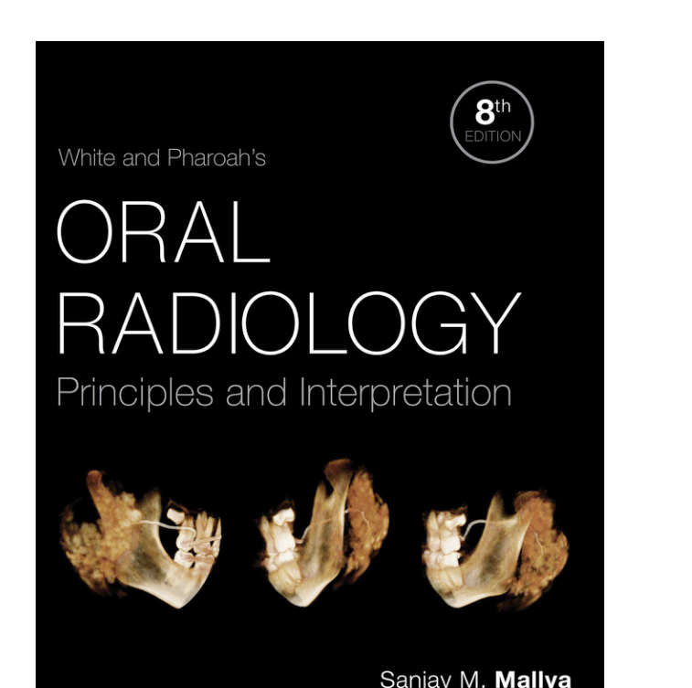
- White and Pharoah’s Oral Radiology: Principles and Interpretation, 8th edition. Sanjay M. Mallya, Ernest W. N. Lam. Elsevier.
Footnotes
-
Original PDF page 1: L10 CT & CBCT, p.1 ↩
-
Original PDF page 2: L10 CT & CBCT, p.2 ↩
-
Original PDF page 3: L10 CT & CBCT, p.3 ↩
-
Original PDF page 4: L10 CT & CBCT, p.4 ↩
-
Original PDF page 5: L10 CT & CBCT, p.5 ↩
-
Original PDF page 6: L10 CT & CBCT, p.6 ↩
-
Original PDF page 7: L10 CT & CBCT, p.7 ↩
-
Original PDF page 8: L10 CT & CBCT, p.8 ↩
-
Original PDF page 9: L10 CT & CBCT, p.9 ↩
-
Original PDF page 10: L10 CT & CBCT, p.10 ↩
-
Original PDF page 11: L10 CT & CBCT, p.11 ↩
-
Original PDF page 12: L10 CT & CBCT, p.12 ↩
-
Original PDF page 13: L10 CT & CBCT, p.13 ↩
-
Original PDF page 14: L10 CT & CBCT, p.14 ↩
-
Original PDF page 15: L10 CT & CBCT, p.15 ↩
-
Original PDF page 16: L10 CT & CBCT, p.16 ↩
-
Original PDF page 17: L10 CT & CBCT, p.17 ↩
-
Original PDF page 20: L10 CT & CBCT, p.20 ↩
-
Original PDF page 23: L10 CT & CBCT, p.23 ↩
-
Original PDF page 24: L10 CT & CBCT, p.24 ↩
-
Original PDF page 25: L10 CT & CBCT, p.25 ↩
-
Original PDF page 26: L10 CT & CBCT, p.26 ↩