Intraoral Radiography1
Dr Dayea Oh OMF Radiologist
Learning Objectives2
- By the end of the lecture, the student should be able to:
- Understand Intraoral Radiography techniques:
- Bitewing radiographs
- Periapical radiographs
- Paralleling
- Bisecting Angle
- Occlusal radiographs
- Understand localisation of an object using intra-oral radiographs
- SLOB rule
- Know technical errors in taking intraoral radiographs
- Understand Intraoral Radiography techniques:
Basic Radiographic Terminology34
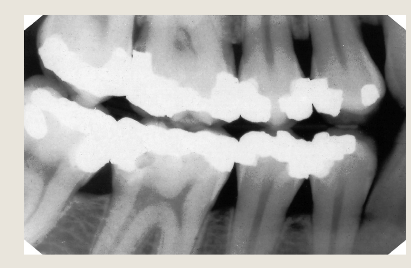
Radiopaque vs Radiolucent
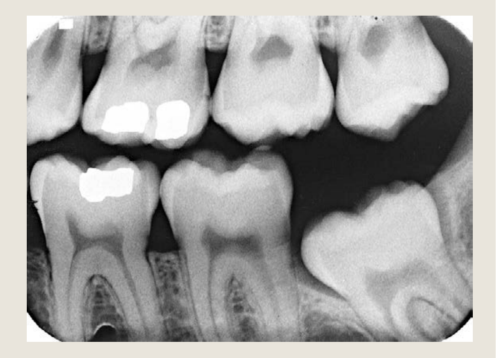
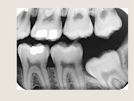
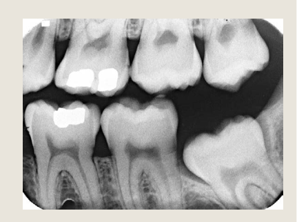
Fig. 1.1 A typical dental radiograph. The image shows the various black, grey and white radiographic shadows. The metallic amalgam fillings have totally stopped the X-ray beam so they appear white or radiopaque.
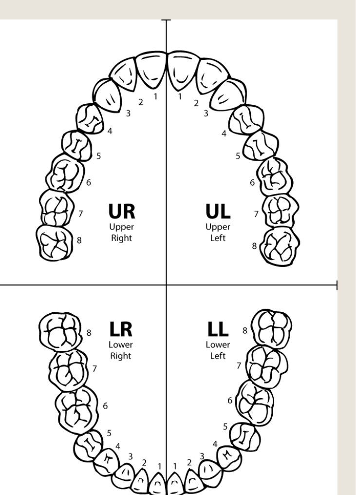
Right Posterior Bitewing Radiograph
Conventional Radiograph = 2D picture made up of a variety of black, white and grey superimposed shadows
- The white or radiopaque shadows on a film represent the various dense structures within the object which have totally stopped the X-ray beam.
- The black or radiolucent shadows represent areas where the X-ray beam has passed through the object and has not been stopped at all.
 |  |
Overview of Intraoral Radiography5
‘Intra’ = inside ‘oral’ = mouth
Radiography – the techniques involved in producing the various radiographic images Radiology – the interpretation of radiographic images (radiographs)
Types of Intraoral Radiographs678
THREE (3) Types
- Bite-wing Radiographs (BW)
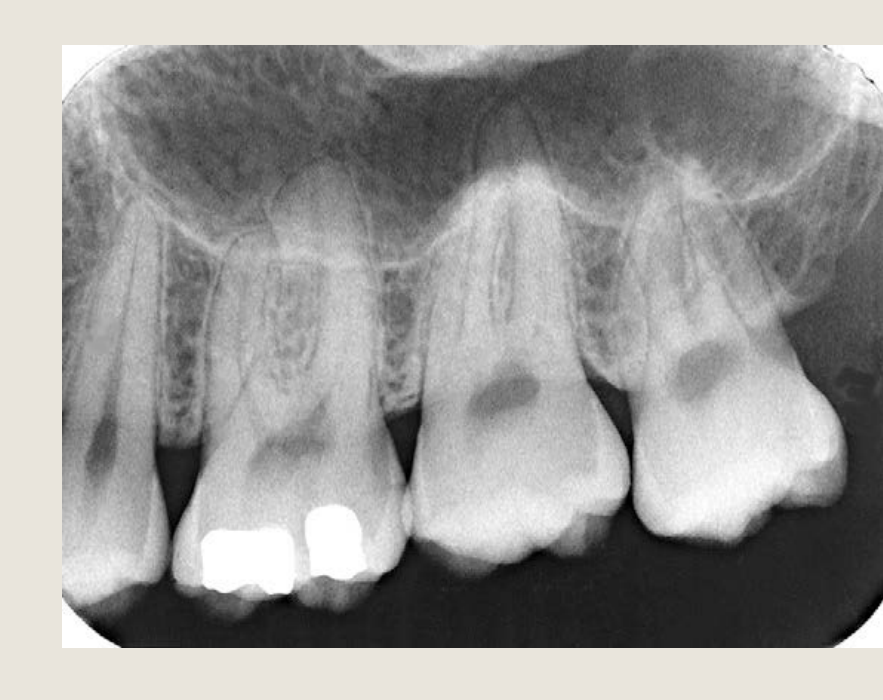
- Periapical Radiographs (PA)
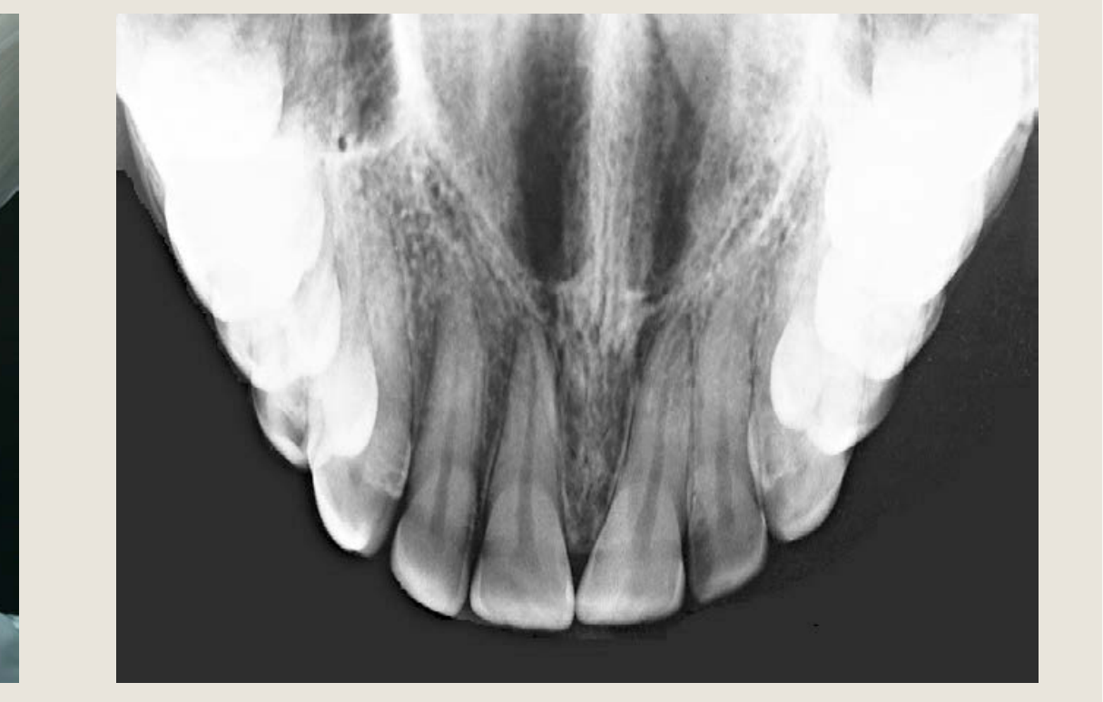
- Occlusal Radiographs / Occlusographs
Upper (or Maxillary) Left Posterior Periapical (PA)
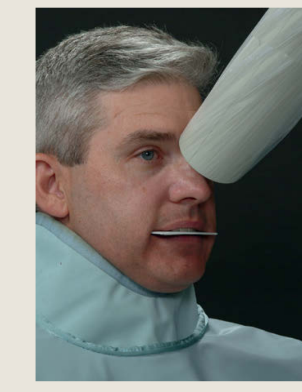
Anterior Maxilla Occlusograph
 |  |  |
 |  |  |
 |  |  |
Analogue Film Sizes9
Analogue radiography → images are chemically processed
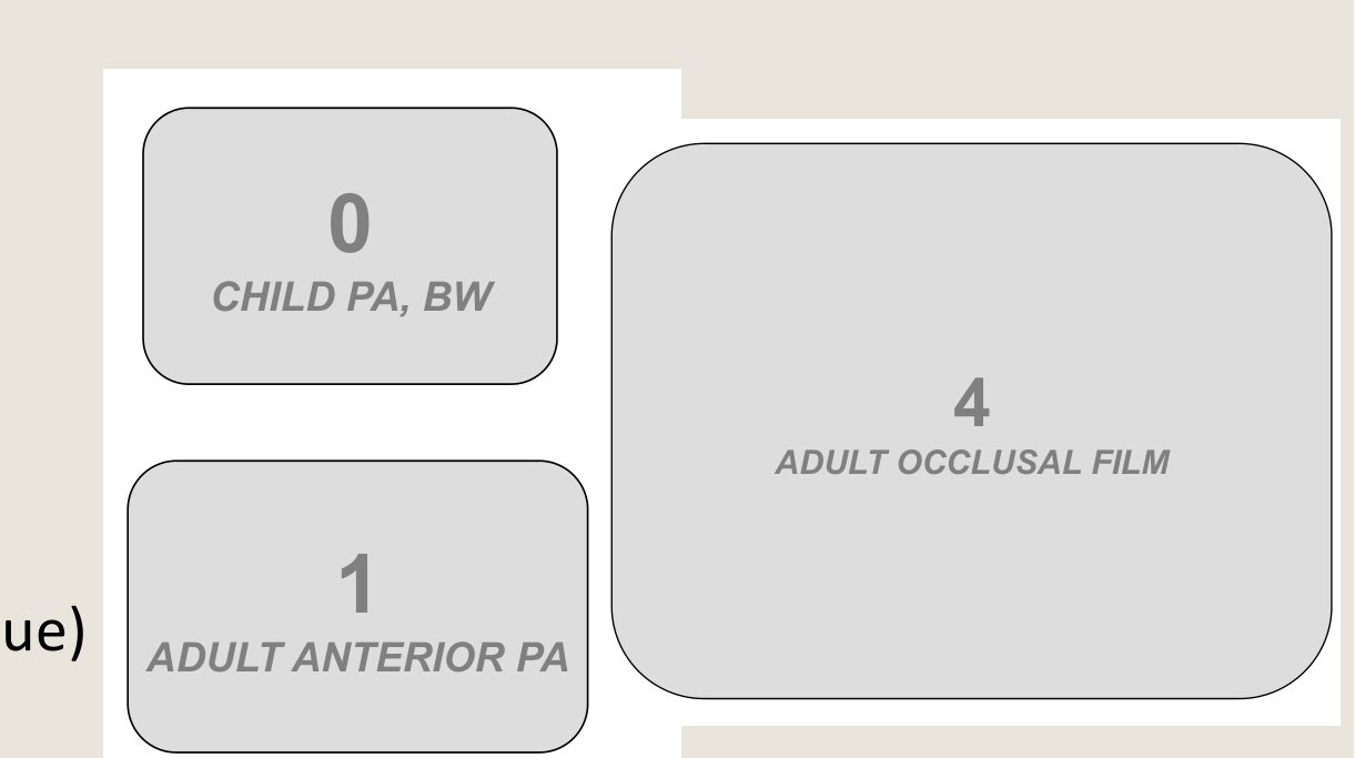
FIVE (5) Sizes
- Size 0
- Used in children for both PA and BW
- Size 1
- Used for adult anterior PA (using paralleling technique)
- Size 2
- Used for adult posterior PA & BW
- Used for adult anterior PA (using bisecting-angle technique)
- Used for occlusographs in children
- Most commonly used
- Size 3
- Extra-long BW (not commonly used)
- Size 4
- Used for occlusographs in adults
On the right side, displayed in a graphic form:
- 0: CHILD PA, BW
- 1: ADULT ANTERIOR PA
- 2: ADULT PA, BW
- 4: ADULT OCCLUSAL FILM
Bitewing Radiography
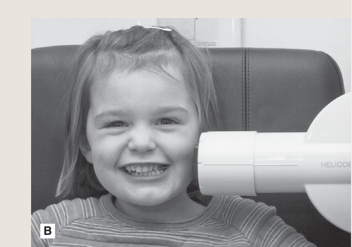
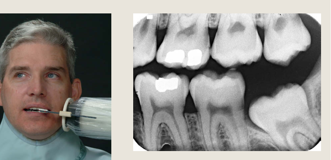
Indications and Coverage101112
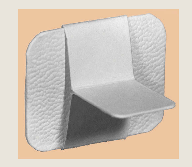
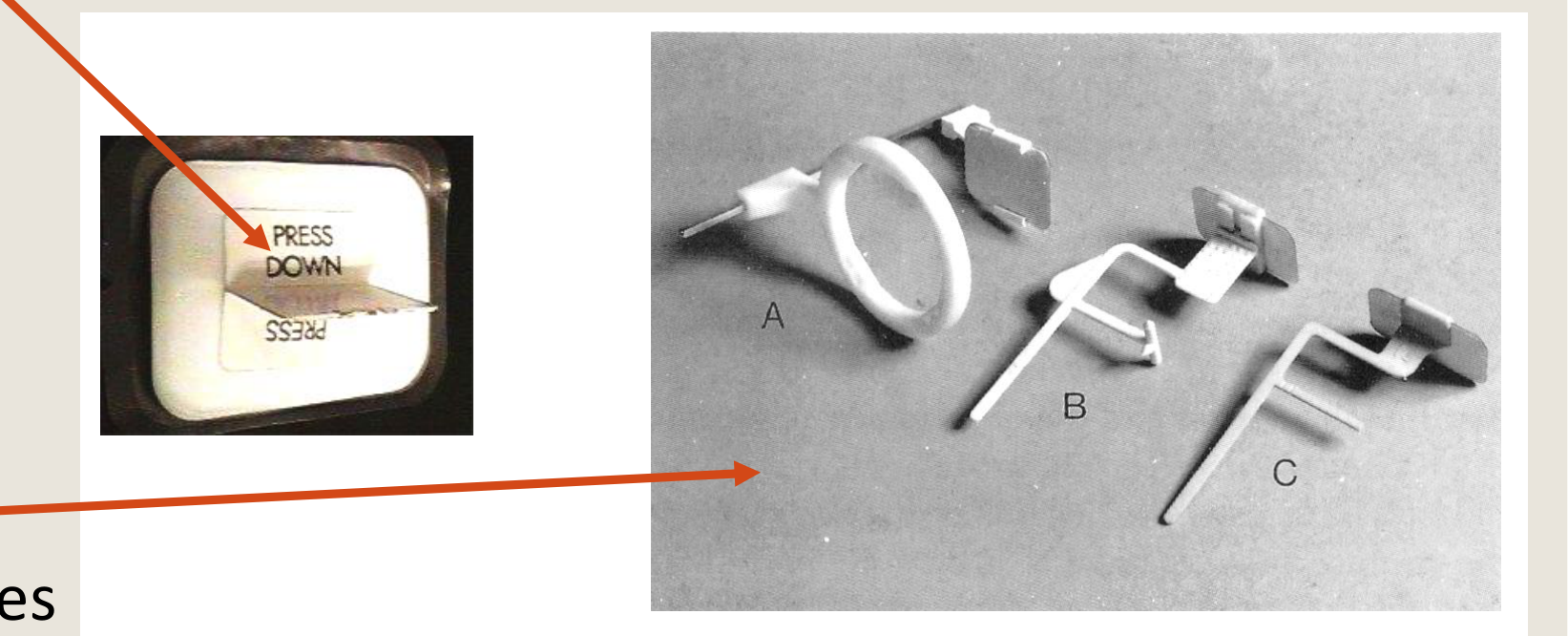
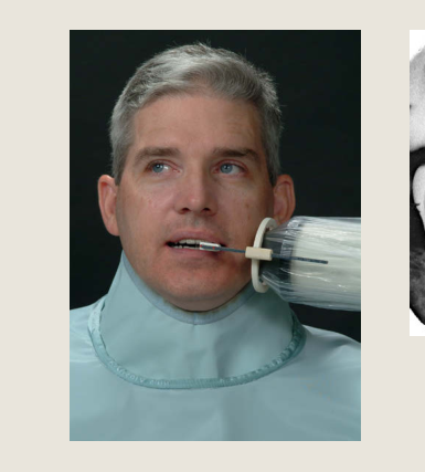
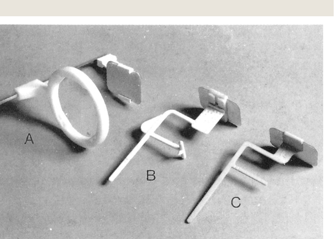
Bitewing (BW) Radiographs Indications Film holder vs Bite tab
A B C A B C
 |  |  |
 |  |  |
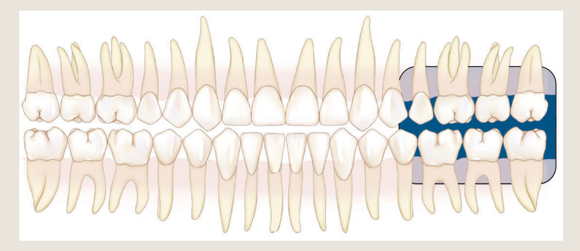 |
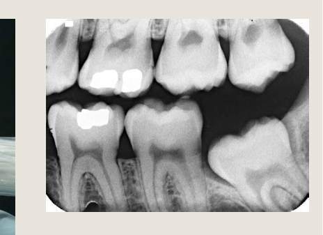
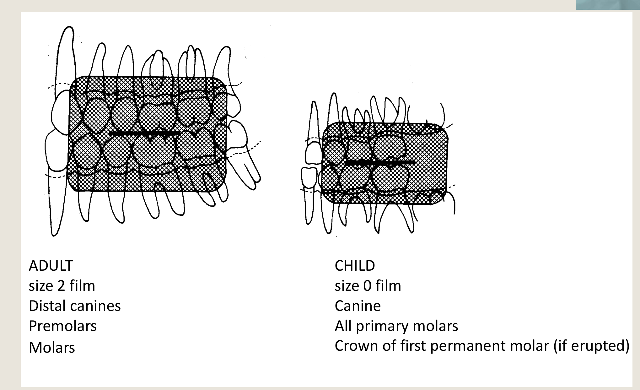
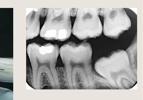
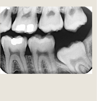
BW Coverage13
ADULT
- size 2 film
- Distal canines
- Premolars
- Molars
CHILD
- size 0 film
- Canine
- All primary molars
- Crown of first permanent molar (if erupted)
BW Coverage
“LEFT POSTERIOR BITEWING” Radiograph
 |  |
 |
Patient and Beam Positioning
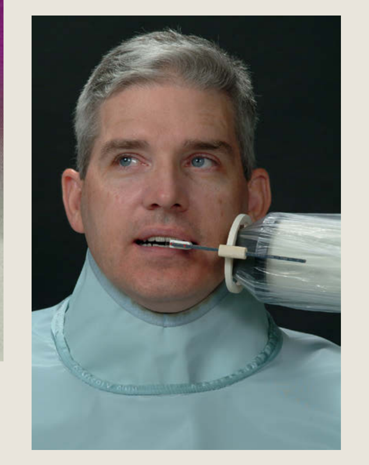
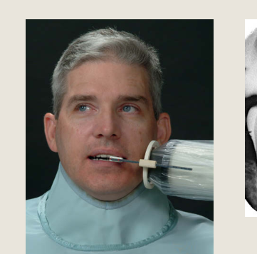
Patient Position14
- Remove all dentures, glasses and other metallic objects (e.g., piercings in line of primary beam)
- Patient’s head is supported by head-rest (of dental chair)
- Patient bites on to the holder/tab
- Ideally, the occlusal plane is parallel to the floor (sit-up position)
 |  |
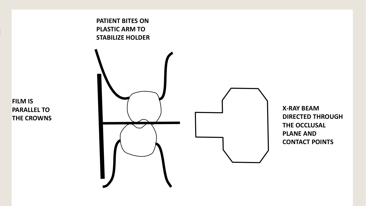 |
Beam / X-ray Cone Position
- Parallel to, and directed through, the occlusal plane
FILM IS PARALLEL TO THE CROWNS X-RAY BEAM DIRECTED THROUGH THE OCCLUSAL PLANE AND CONTACT POINTS PATIENT BITES ON PLASTIC ARM TO STABILIZE HOLDER
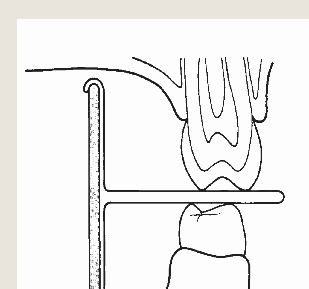
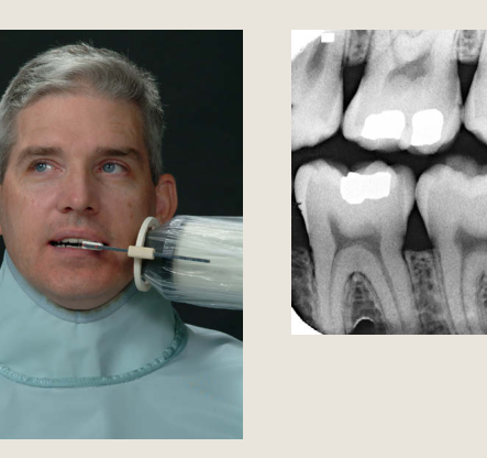
Bitewing Technique Using Film Holders15
 |  |
 |
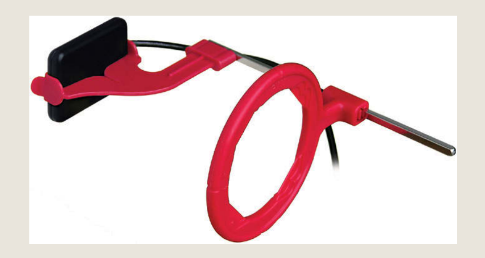
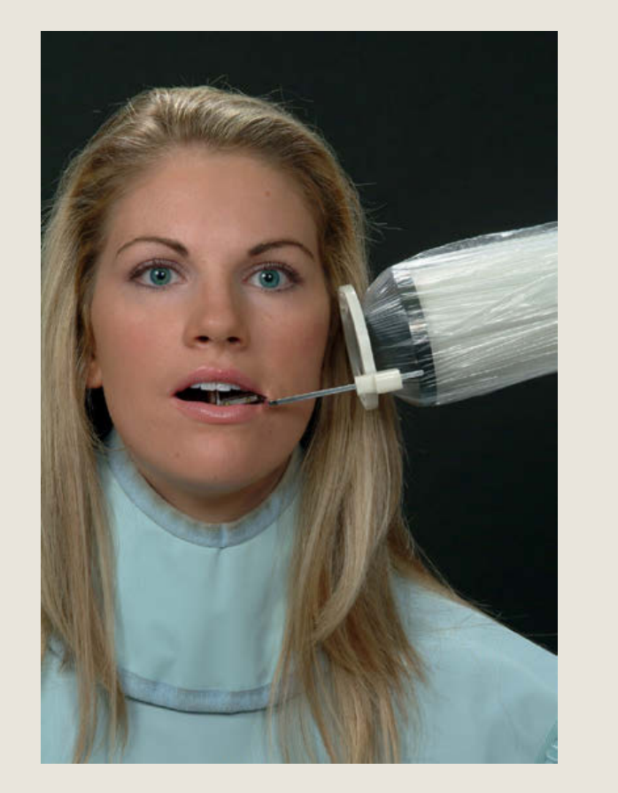
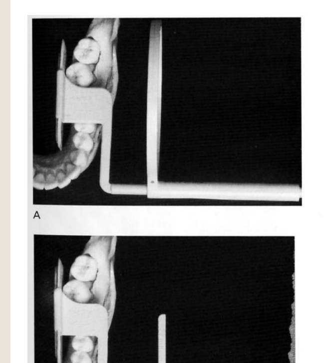
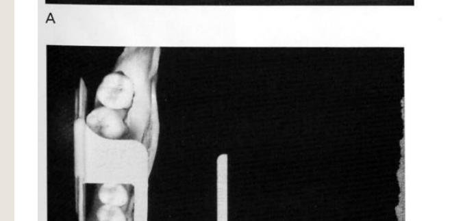
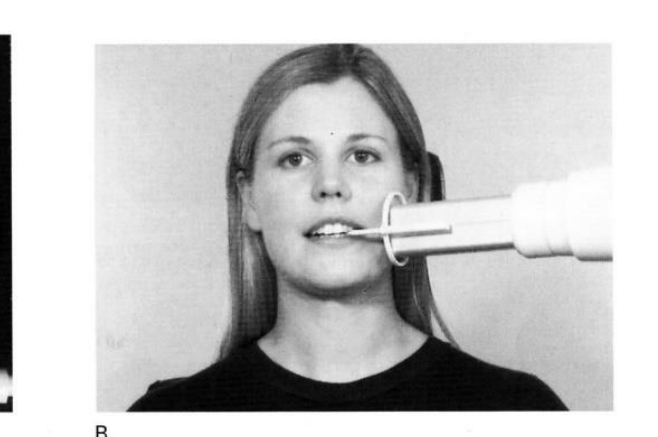
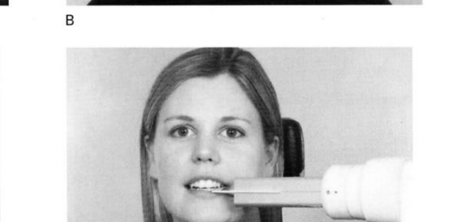
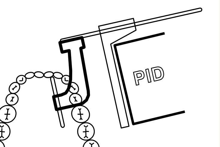
Film Holder16
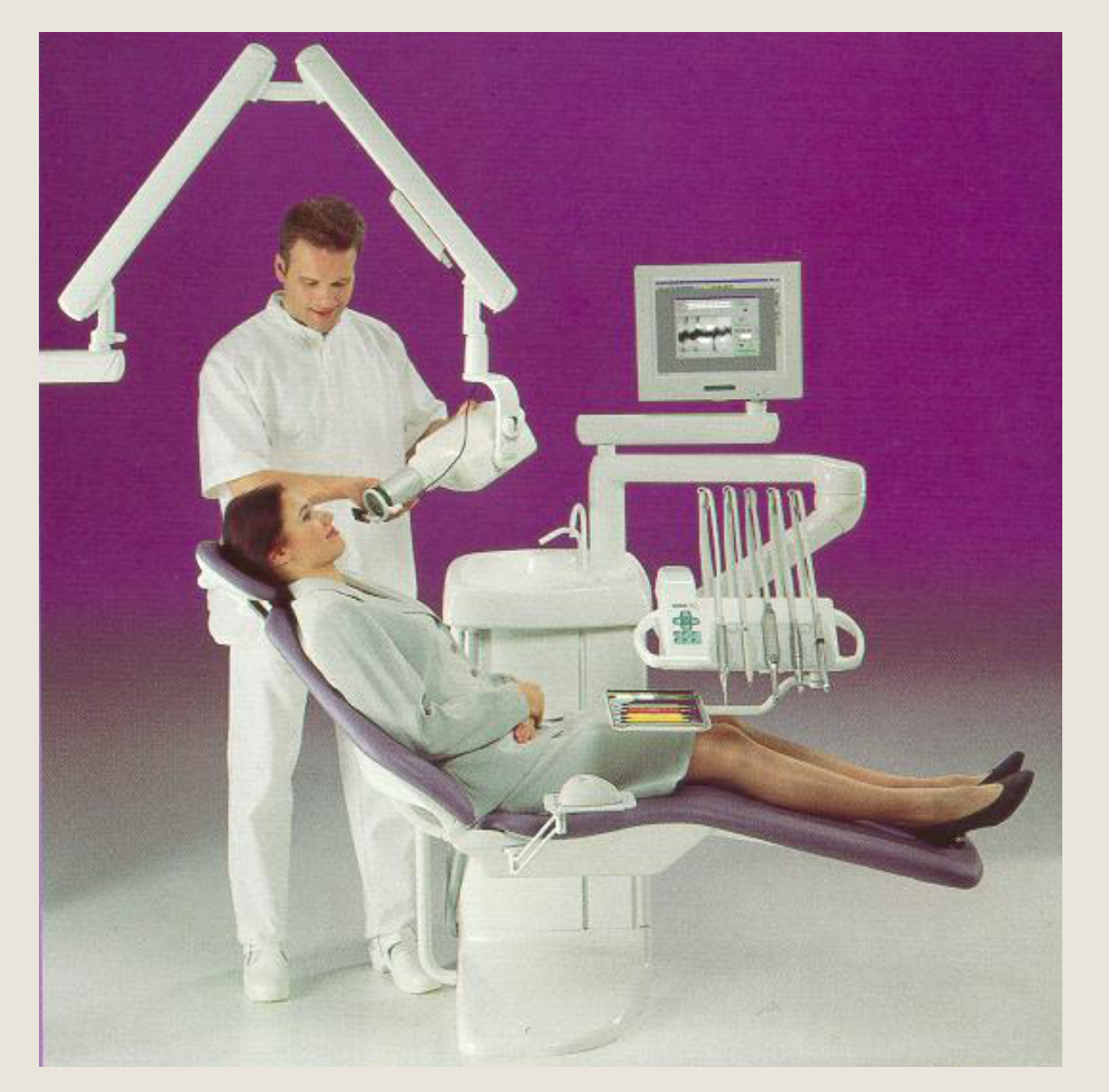
Use the holder at all times, if possible
VERTICAL AND HORIZONTAL ANGULATIONS ESTABLISHED BY THE HOLDER
LESS TECHNIQUE SENSITIVE
Receptor Placement. Place the receptor between the tongue and the teeth, far enough from the lingual surface of the teeth to prevent interference by the palate on closing and parallel to the long axes of the teeth. The anterior border of the receptor should extend beyond the contact area between the mandibular canine and the first premolar. Hold the receptor in place until the patient’s mouth is completely closed. Holding the receptor while closing prevents it from being displaced distally.
Note: the film / receptor is sitting far away from the teeth when used with holder (thus, not creating any angulation)
 |  |  |
 |  |  |
Bitewing Technique Using Adhesive Tabs
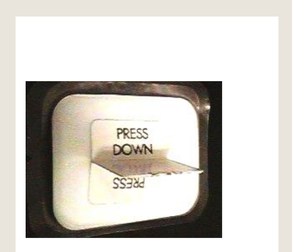
Paper / Adhesive Tab17
- Horizontal and vertical angulations of primary beam must be manually adjusted by operator
- No guidance unlike that provided by a film holder
- Very technique sensitive
- Unrepeatable
 |  |
Horizontal Alignment of the Cone18
no film holder
WHY?
- Ensures the beam will clear the contact points so we can detect interproximal caries
- Ensure we cover all the film with the cone
HOW?
- Ensure that the film covers all the teeth
- Try to keep the film as close to the lingual surfaces of the teeth as possible
- Avoid bending the film
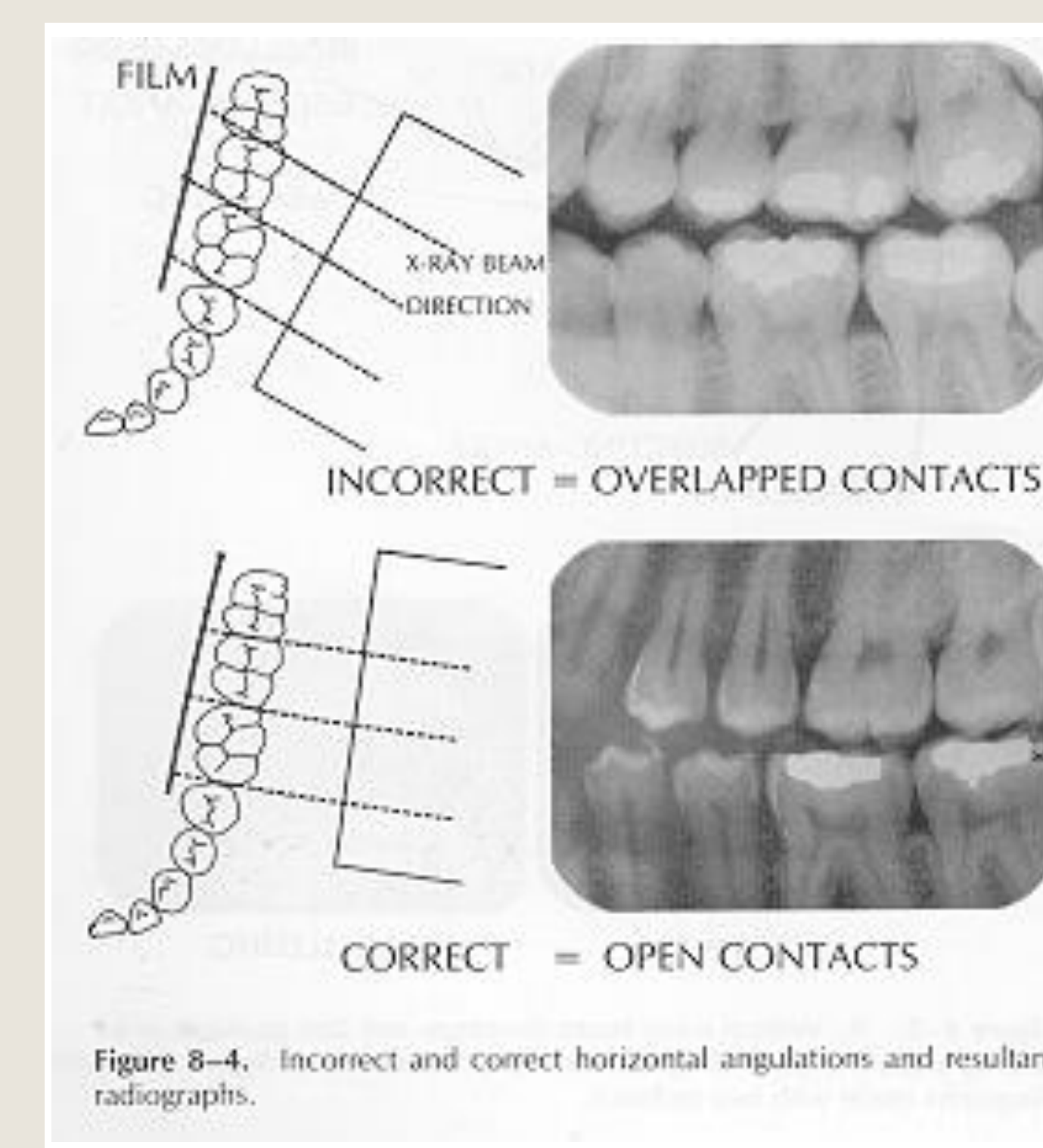
- Align the cone so that it is parallel to the arch
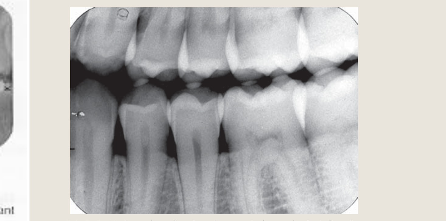
wrong horizontal alignment ❎ - overlapping of teeth
FIG. 9-4
Horizontal overlapping of crowns is the result of misdirection of the central ray.
 |  |
 |
Vertical Alignment of the Cone
no film holder
-
20º
-
0º
-
+8 to +10
-
AIM FOR PRIMARY BEAM TO PASS +8 to +10 FROM THE OCCLUSAL PLANE
-
WE ONLY ADJUST THE VERTICAL WHEN USING TABS NOT FILM HOLDERS!!
The film / receptor sits right next to the teeth, creating slanting
Clinical Problems and Solutions
Clinical Problems19
- Mandibular Tori
- Bone overgrowth on the lingual surface of the mandible
- Difficult to place film
- How to correct: Use the thinnest film (e.g., analogue film or digital PSP plate) and place it lingual to the torus
- Missing Teeth
- Difficult to stabilise / hold film
- How to correct: Place cotton rolls in the edentulous space to prevent film rotation
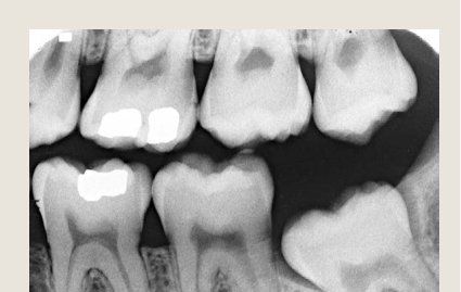
If you examine the patient first you will avoid the majority of mistakes & retakes
Periapical Radiography
Indications20
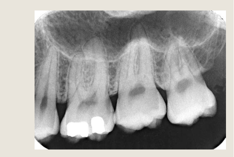
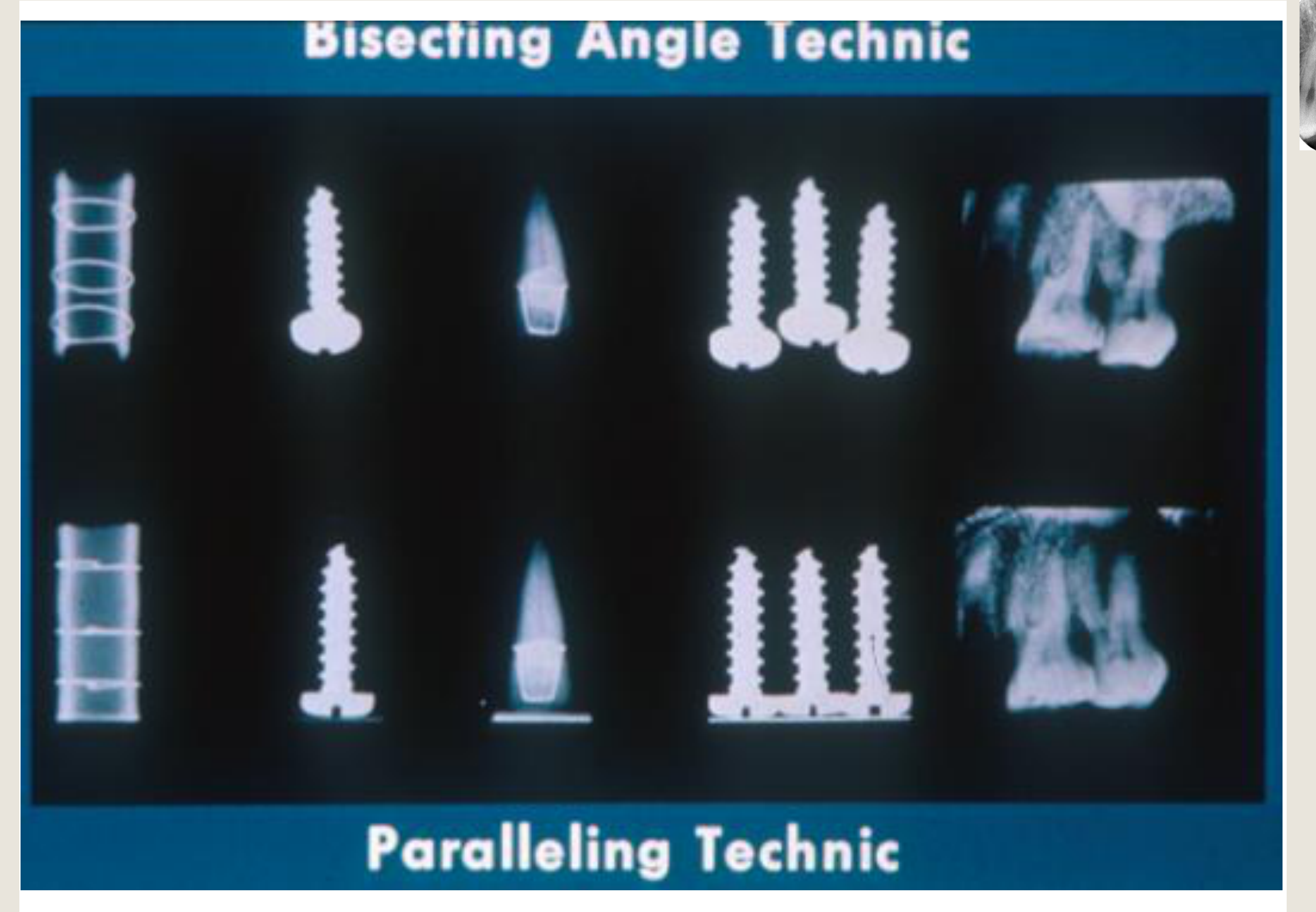
Paralleling Technique Vs Bisecting Angle Technique
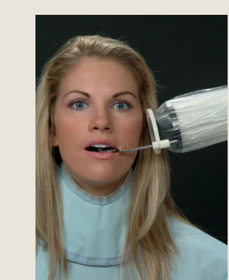
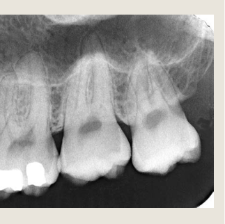
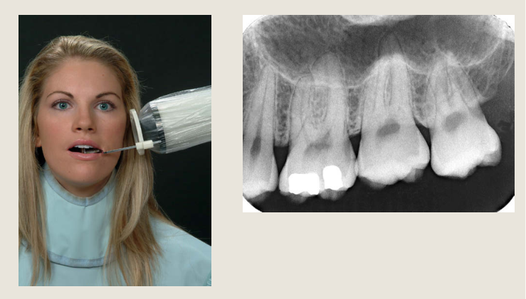
Indications and Coverage Requirements2122
Periapical = around the apex
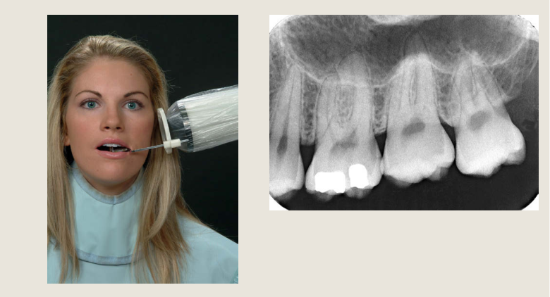
The intention is to visualize the crown, root and periapical tissues
 |  |  |
 |  |  |
Indications23
- Periapical inflammation / pathology
- Root resorption
- Root fractures
- Endodontic therapy (pre, peri & post)
- Localisation of impacted, missing, supernumerary teeth and foreign bodies
- Implant status
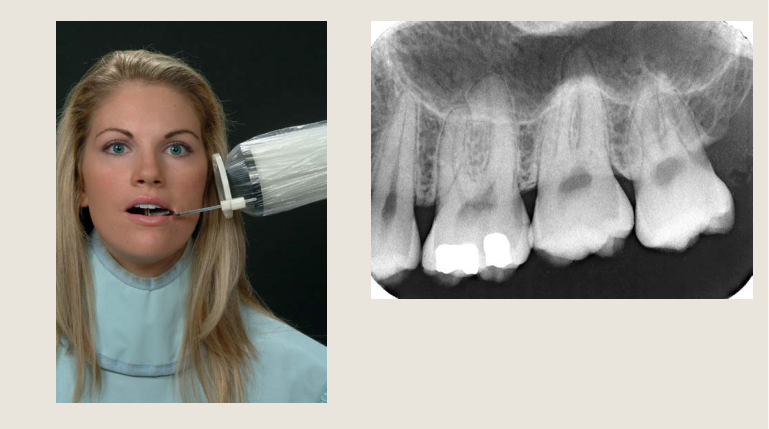
Techniques
- Paralleling (long cone)
- Bisecting Angle
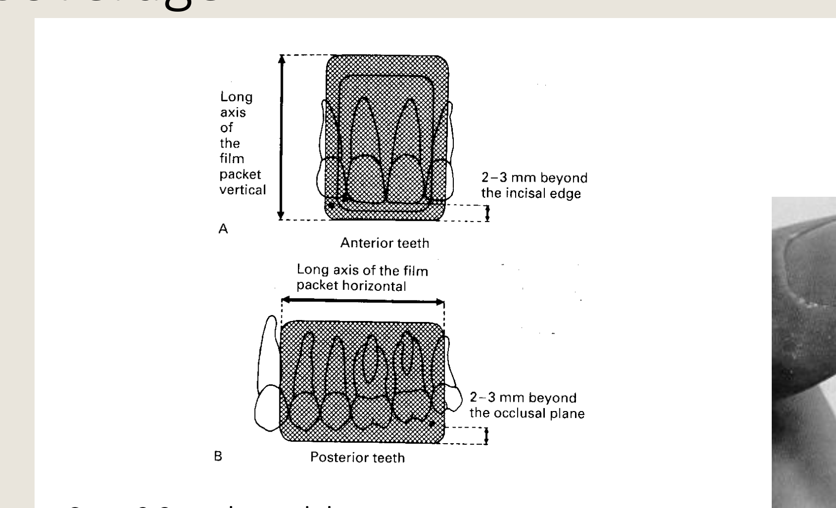
A
- Long axis of the film packet vertical
- Anterior teeth
- 2–3 mm beyond the incisal edge
B
-
Long axis of the film packet horizontal
-
Posterior teeth
-
2–3 mm beyond the occlusal plane
-
Cover 2-3 mm beyond the crowns
-
Demonstrate all roots
-
Demonstrate the apical tissues
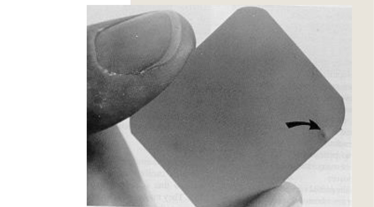
‘occlusal dot’ marked on film
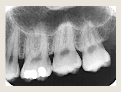
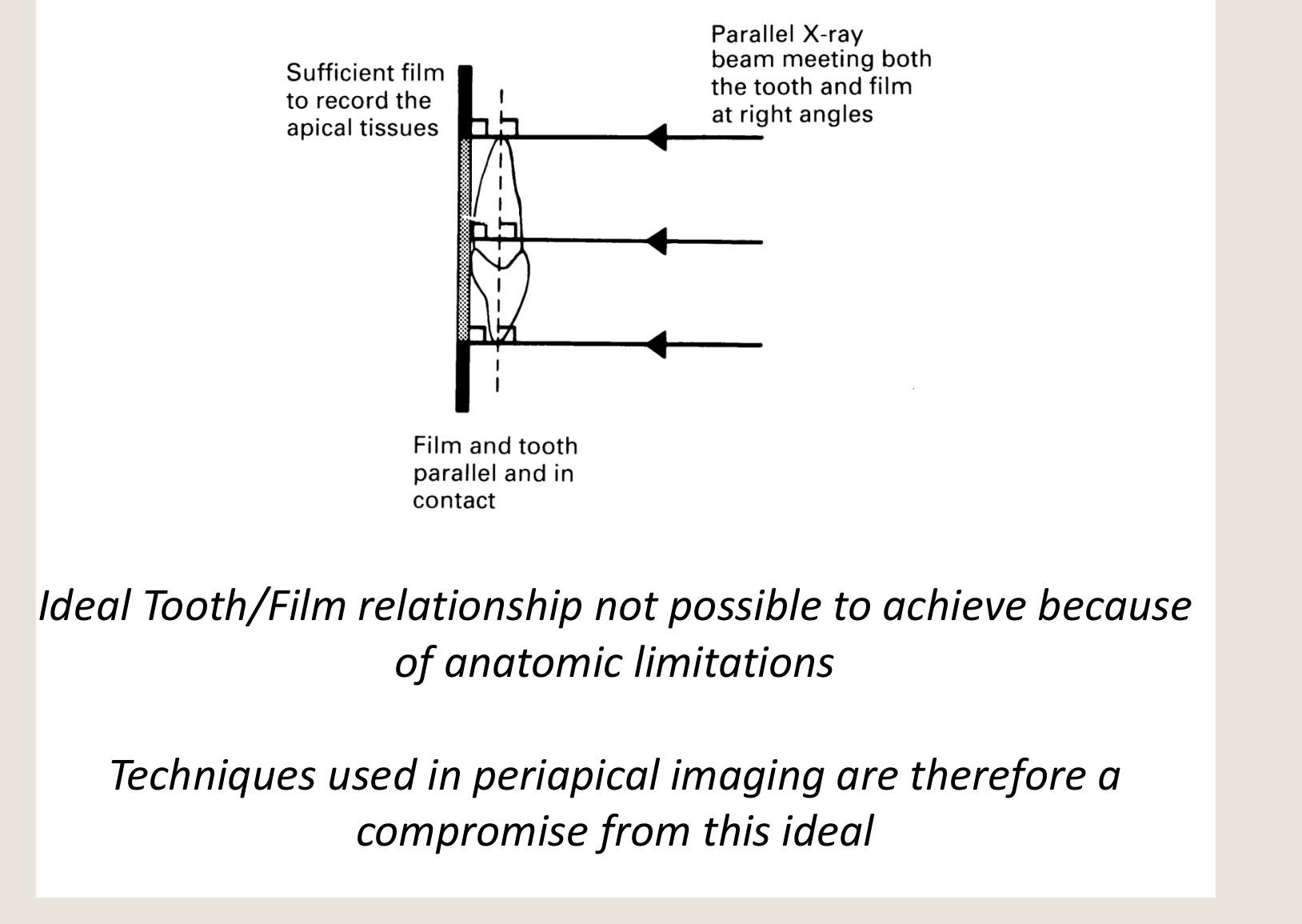
Ideal PA24
Sufficient film to record the apical tissues
Parallel X-ray beam meeting both the tooth and film at right angles
Film and tooth parallel and in contact
Ideal Tooth/Film relationship not possible to achieve because of anatomic limitations Techniques used in periapical imaging are therefore a compromise from this ideal
-
Same size
-
Same shape
-
Good contrast
-
Good detail
-
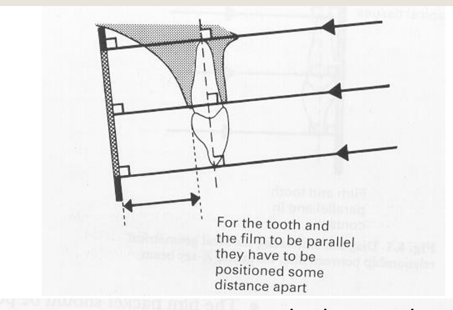
Film parallel to the long axis of the tooth
-
Primary beam perpendicular to the film
 |  |
 |
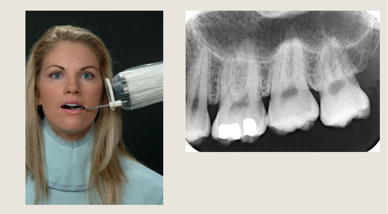
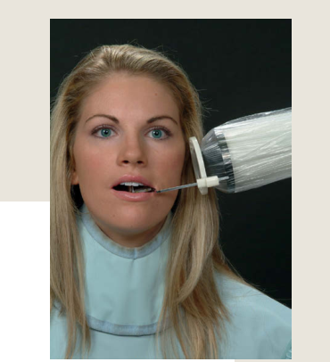
The Paralleling Technique2526
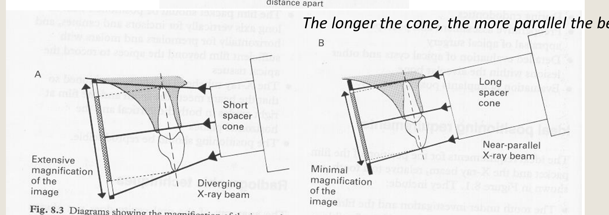
The longer the cone, the more parallel the beam
A Short spacer cone Diverging X-ray beam Extensive magnification of the image
B Long spacer cone Near-parallel X-ray beam Minimal magnification of the image
Fig. 8.3 Diagrams showing the magnification of the image that results from using A a short cone and a diverging X-ray beam and B a long cone and a near-parallel X-ray beam.
 |  |
 |
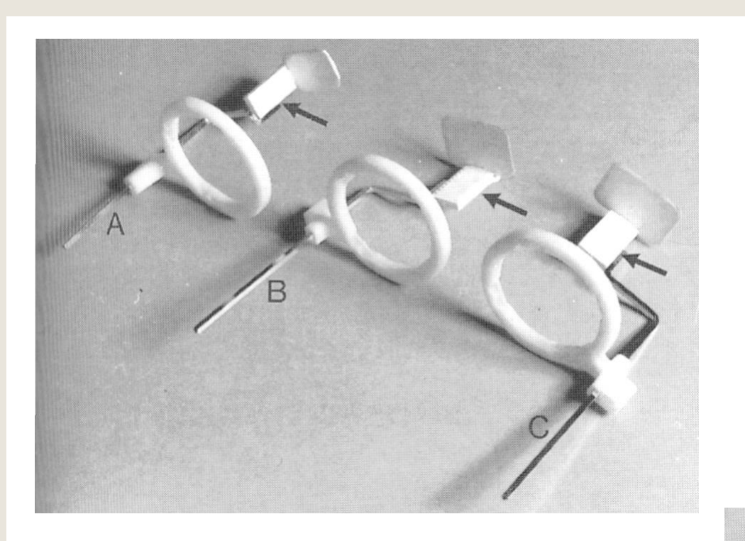
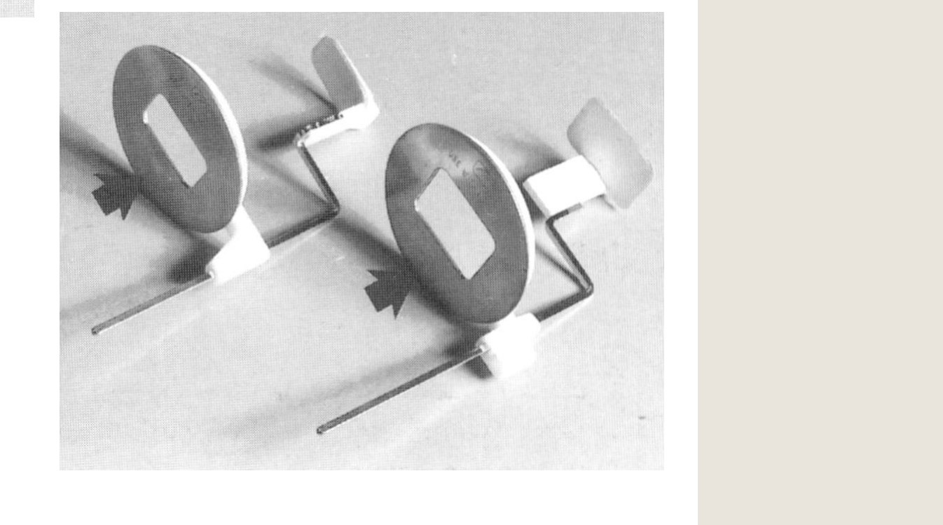
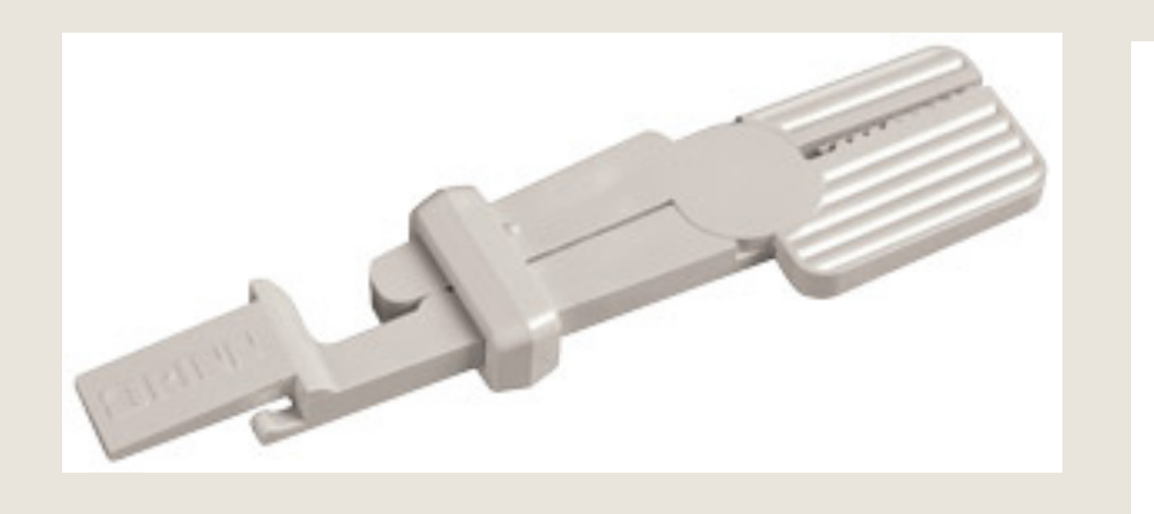
Examples of Film Holders27
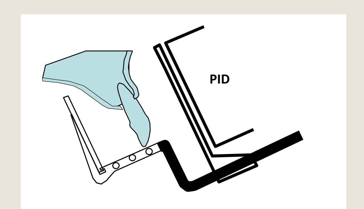
With PID guidance rings
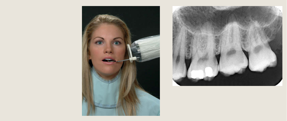
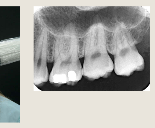
Paralleling technique always requires film holders.
- Optimally achieved using film holders with PID guidance rings
- ++ Accuracy
- Less technique sensitive - horizontal and vertical angulations determined by film holder
- Recommended for:
- Endodontic therapy = accurate measurement of length is critical
- Long term evaluation of crestal bone height around implants
 |  |
 | 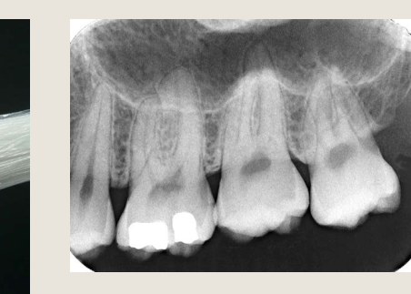 |
Advantages and Disadvantages28
- Dimensionally accurate
- Accurate determination of bone height
- Accurate assessment of dental caries
- Reduced superimposition of the zygoma
- Reduced skin exposure due to greater kVp and parallel beam
Disadvantages
- More difficult to place film
- More uncomfortable for the patient
- Higher kVp machine required
- Long cone and film holders required
 |  |
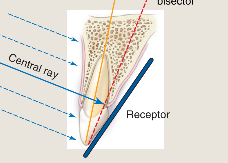
The Bisecting Angle Technique2930
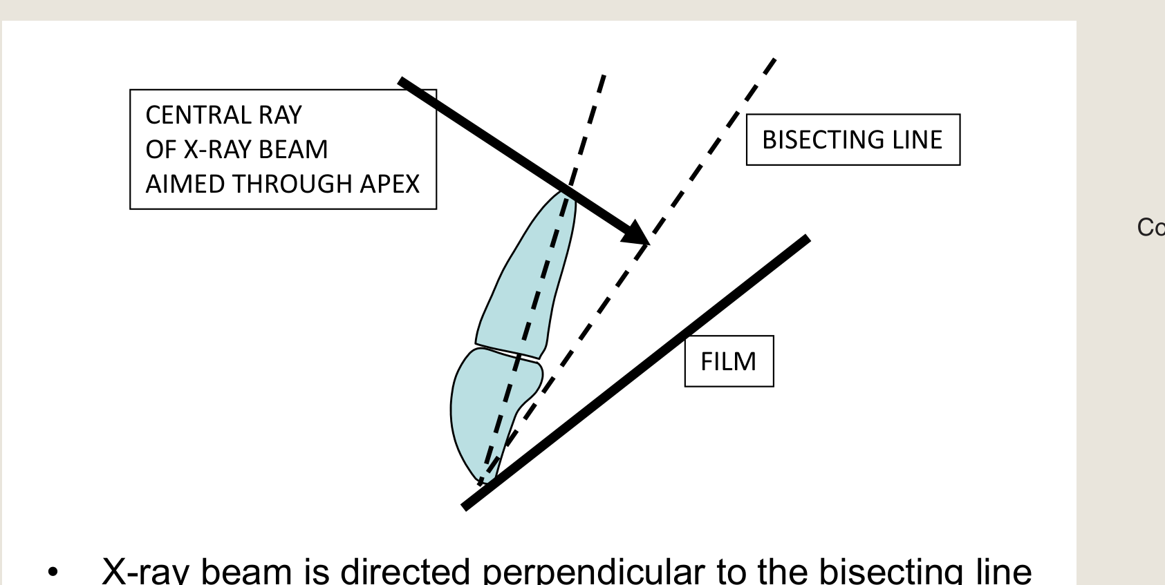
CENTRAL RAY OF X-RAY BEAM AIMED THROUGH APEX
BISECTING LINE
FILM
- X-ray beam is directed perpendicular to the bisecting line
- Vertical angulation must be determined manually
- Receptor is placed as close to tooth as possible
Central axis of tooth
Imaginary bisector
Collimated beam
Central ray
Receptor
In any 90-degree arc, there is one angle (bisecting angle) that will allow an x-ray beam to cast an accurate shadow of the tooth on the film.
[Image showing close-up of dental film holder in patient’s mouth]
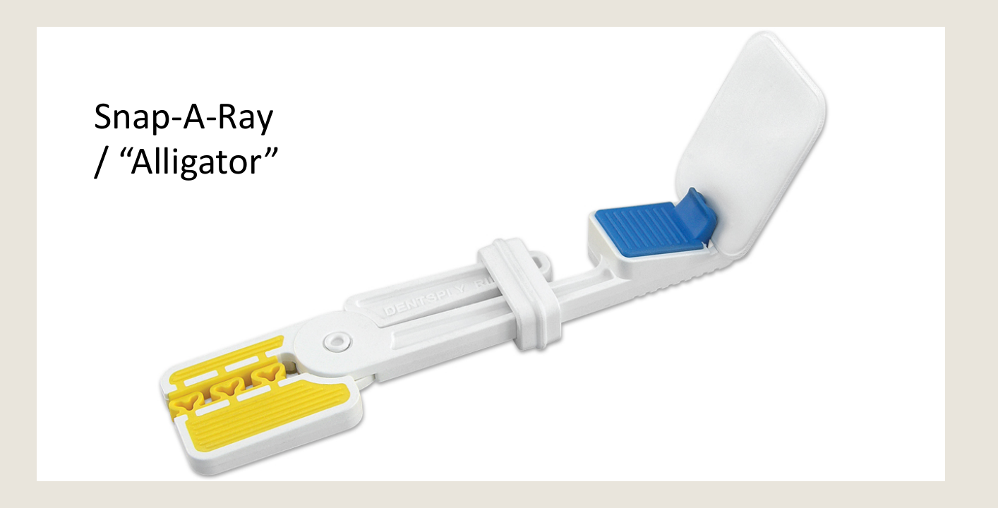
Snap-A-Ray / “Alligator”
Note: no beam aiming device
https://dooclip.me/video/bzreH0NM4fk?id=bzreH0NM4fk
 |  |
 |  |
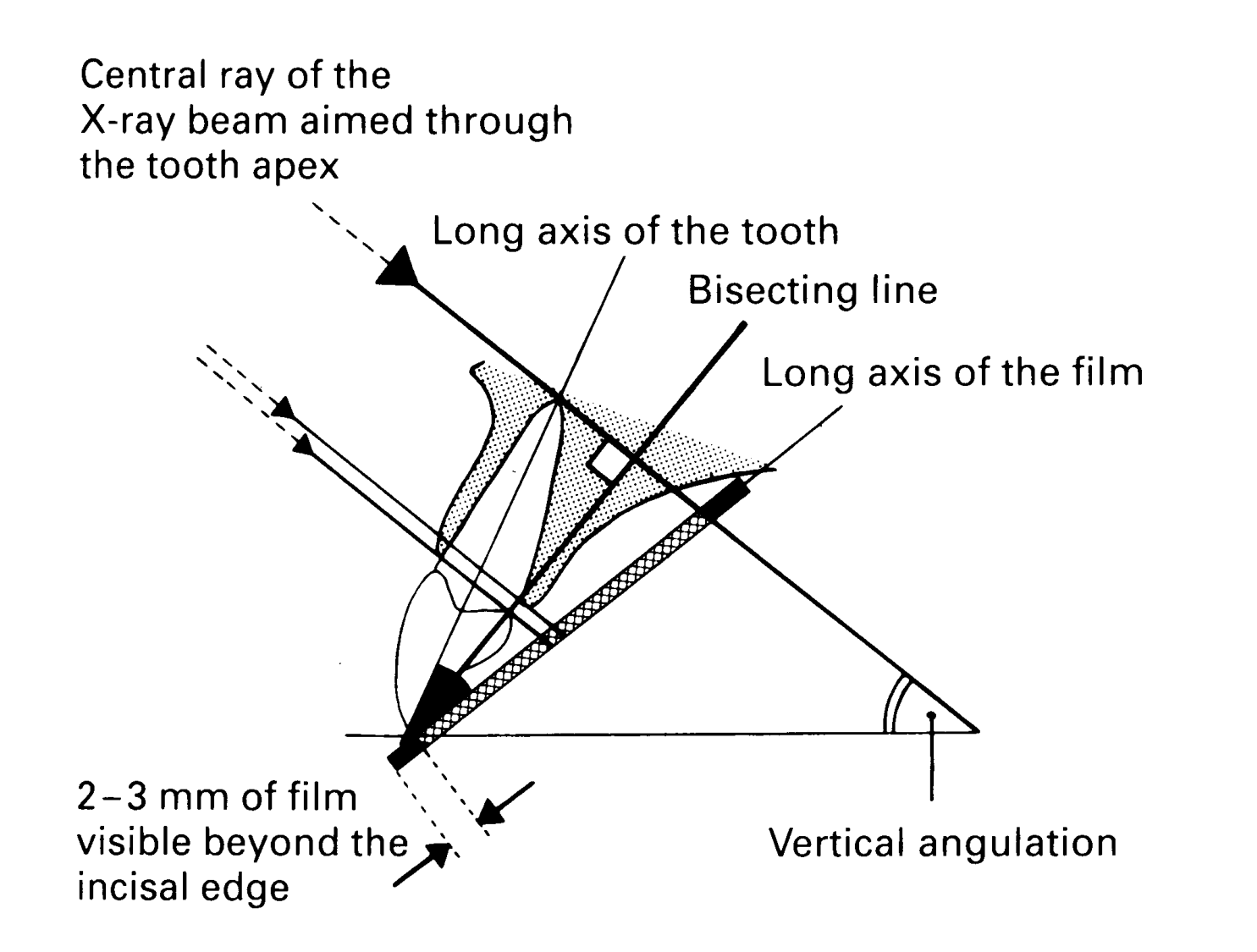
Horizontal and Vertical Angulation31
Central ray of the X-ray beam aimed through the tooth apex
Long axis of the tooth
Bisecting line
Long axis of the film
2-3 mm of film visible beyond the incisal edge
Vertical angulation
Horizontal Angulation
- Horizontal angulation must be corrected manually
- PID → Same as the bite tab technique in bitewing (BW)
Vertical angulation faults
Modified Techniques for Anterior Teeth32
Modified bisecting angle technique – upper anterior
CONE A c film D X° B
“Sao Biscuit” technique for kids
Modified bisecting angle technique – lower anterior
C b Y° A CONE film
Occlusal Radiography3334
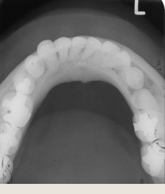
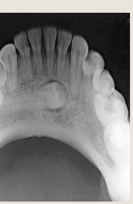
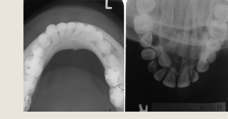
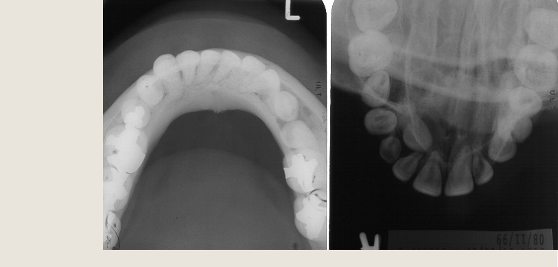
Occlusal Radiographs / Occlusographs
- Largest intraoral film
- Will visualize hard palate, floor of mouth, dentition
Demonstrates:
- Trauma / pathology
- Eg. Alveolar bone fracture, Salivary stones, etc.
- Localization unerupted/impacted teeth
- Localization supernumerary teeth
- View developing anterior dentition
 |  |
 |
Maxillary Occlusal Projections35
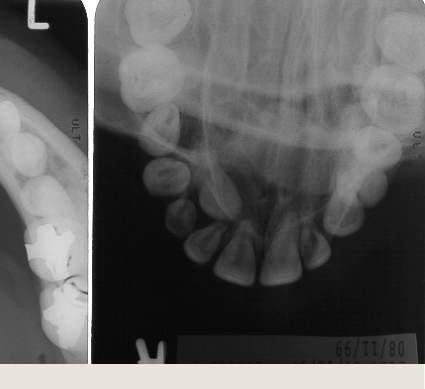
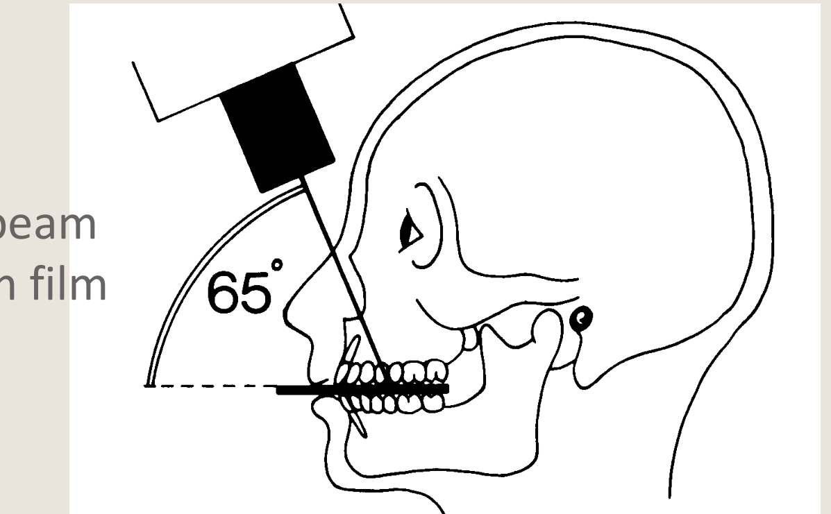
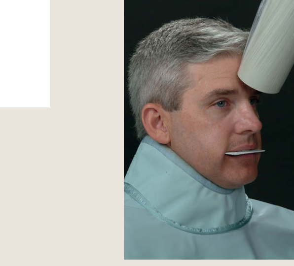
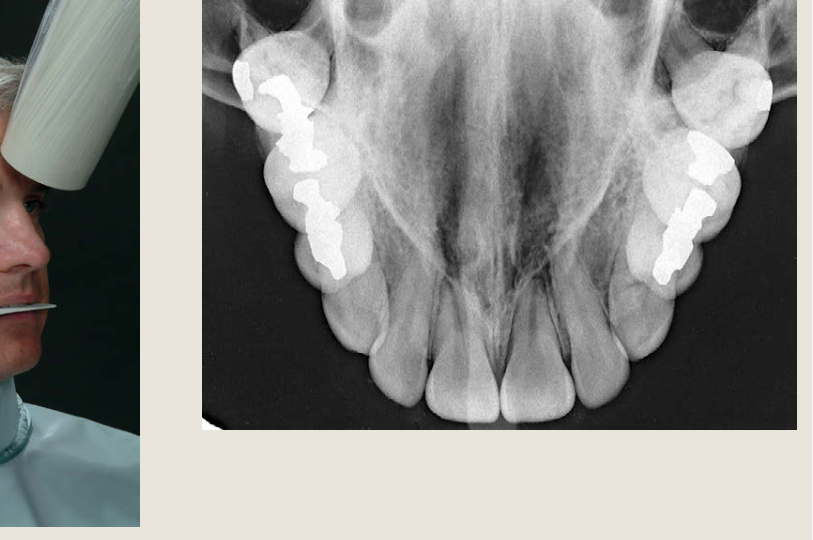
Maxillary Anterior Occlusal36
Above the nose bridge
Primary beam +65° from film
This projection shows the palate, zygomatic processes of the maxilla, anteroinferior aspects of each antrum, nasolacrimal canals, teeth from second molar to second molar, and nasal septum.
 |  |  |
 |  |
Vertex Occlusal37
Above the head → more anatomic structures exposed 😞
Very rarely used - no longer recommended
Dosage +++ Proximity to retinal tissues
Mandibular Occlusal Projections38
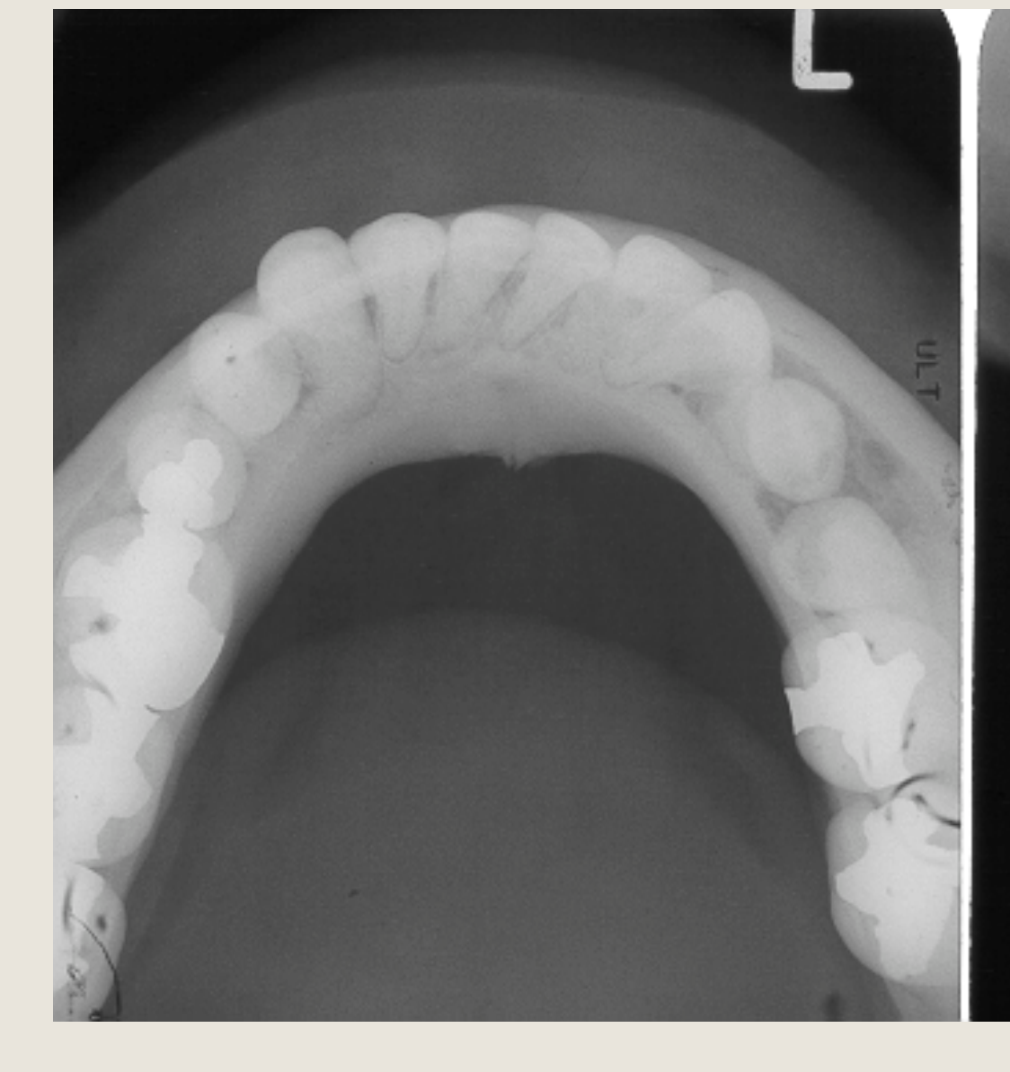 | 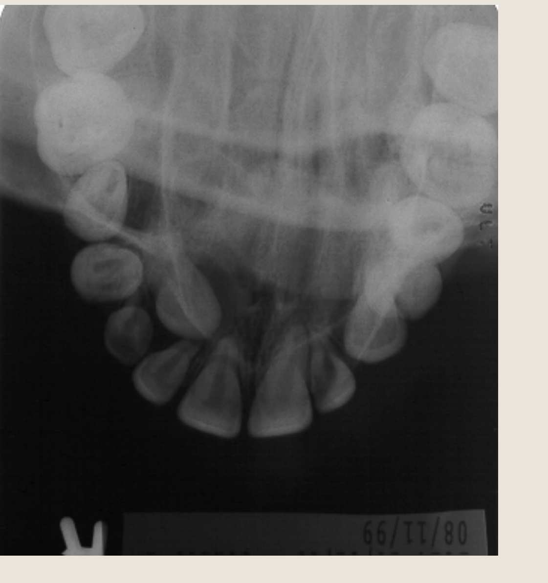 |
Mandibular True Occlusal39
Primary beam perpendicular to film
This projection reveals the lingual and buccal plates of the mandible from second molar to second molar. When this view is made to examine the floor of the mouth (e.g., for sialoliths), the exposure time should be reduced to half the time used to create an image of the mandible.
Localization Techniques404142
Localisation of Objects Using Intra-oral Film
TO DETERMINE:
- Bucco-lingual location of impacted teeth such as unerupted ectopic canines
- Location of a foreign body in the bucco-lingual dimension
Handy if you don’t have access to 3D imaging e.g. Cone Beam CT
Techniques for Localisation
- Two Techniques
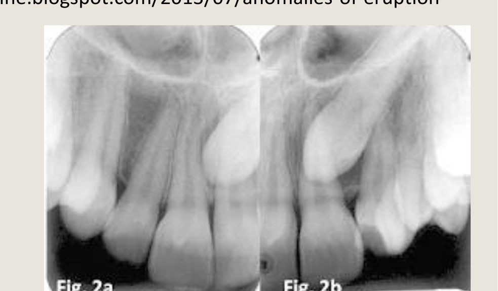
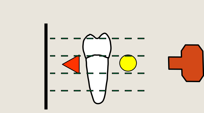
- Tube Shift Technique / Parallex Technique / Clark’s Rule
- Horizontal Shift
- Vertical Shift
- Right Angle Technique / Miller’s Technique
- Tube Shift Technique / Parallex Technique / Clark’s Rule
 |  |  |
 |  |  |
The Tube Shift Technique4344
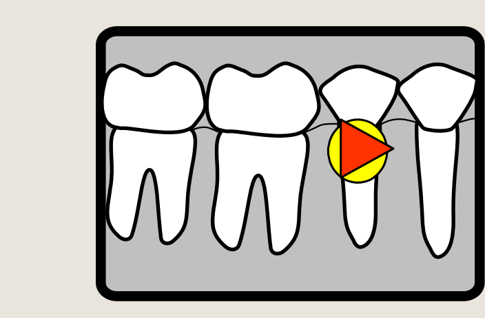
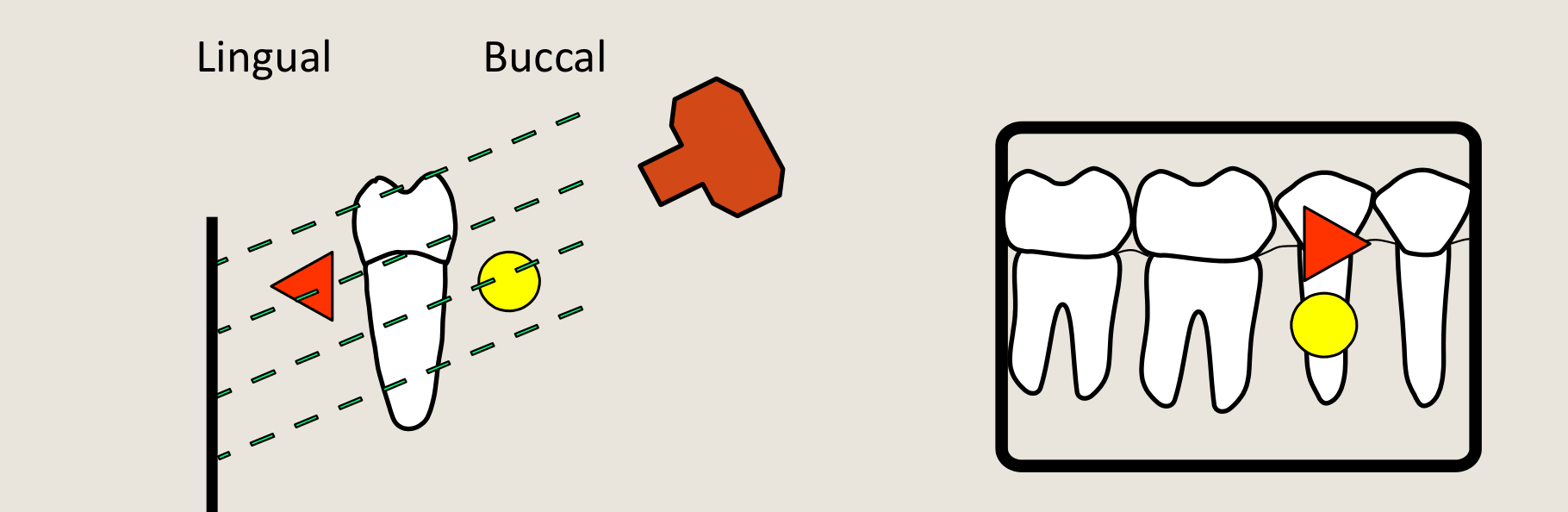
#1 - The Tube Shift Technique
- Two PA images taken
- Film #1 = centered over area of interest and taken
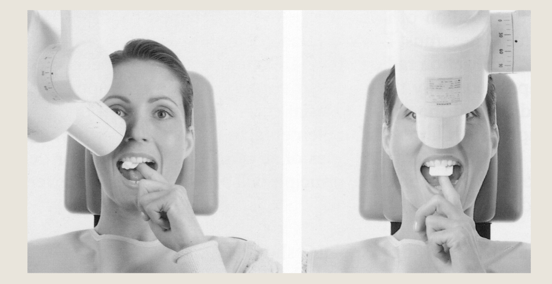
- Film #2 - tube is shifted EITHER HORIZONTALLY OR VERTICALLY 30-40º and second image is taken
- Tube may be shifted in either the HORIZONTAL or VERTICAL directions
- The direction of motion of the impacted tooth/foreign body relative to the tube movement shows its location
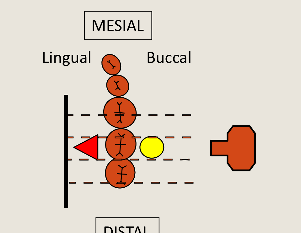
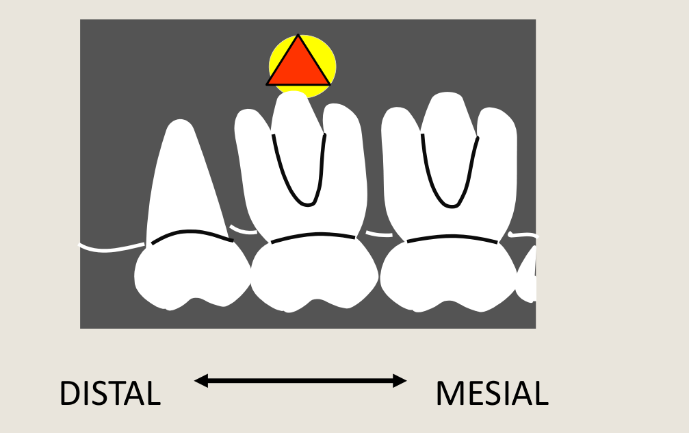
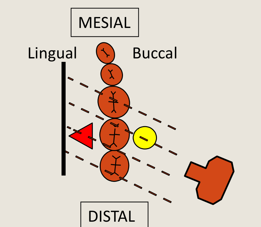
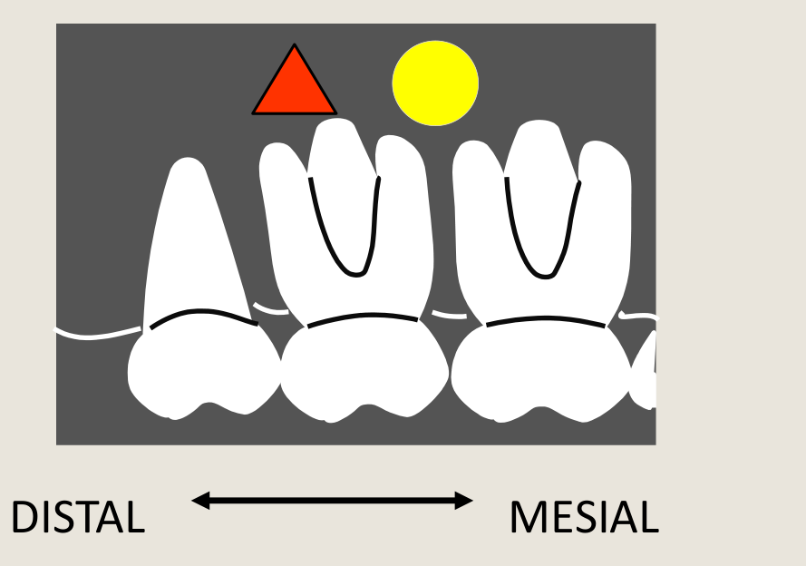
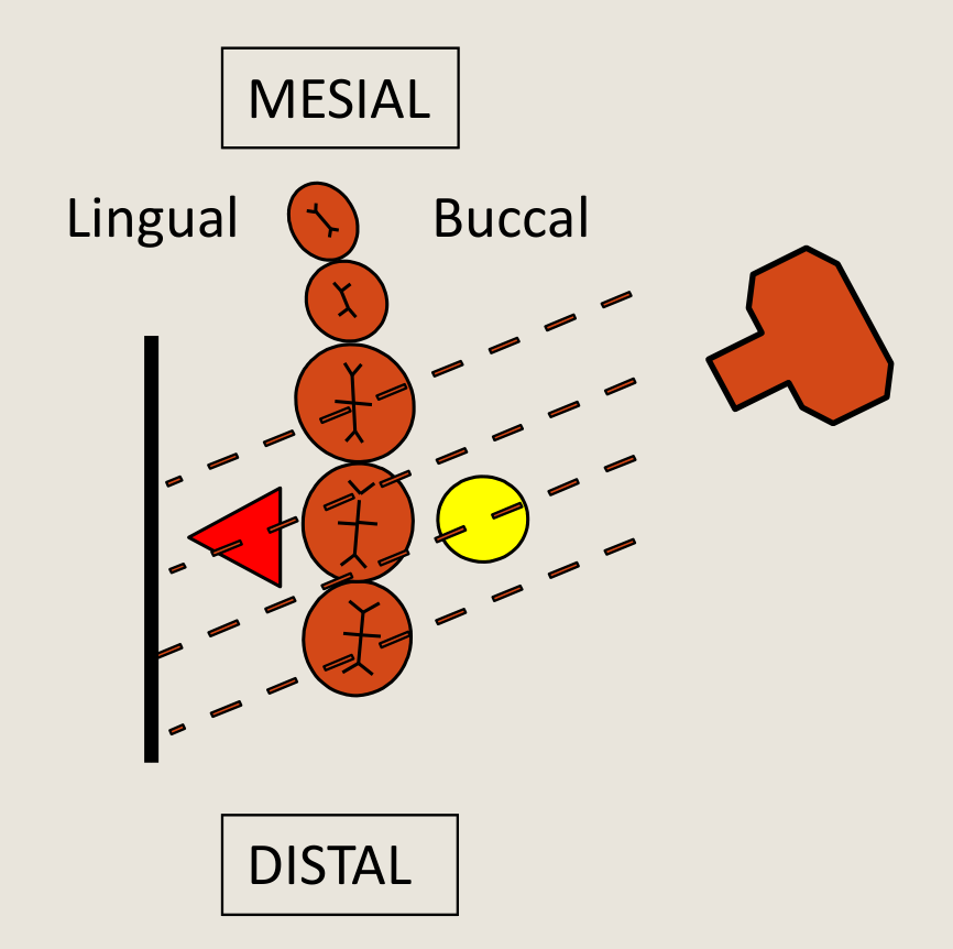
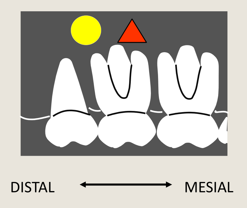
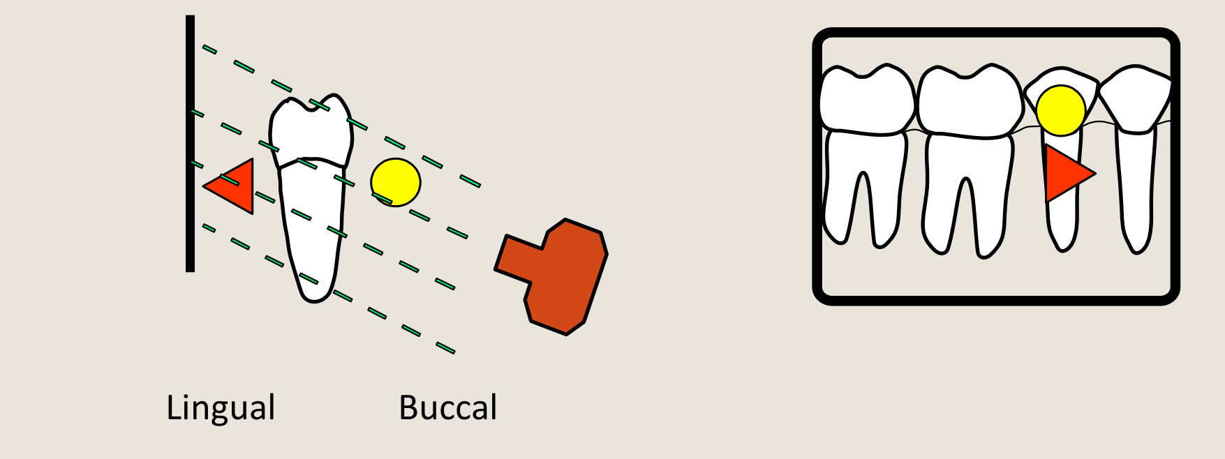
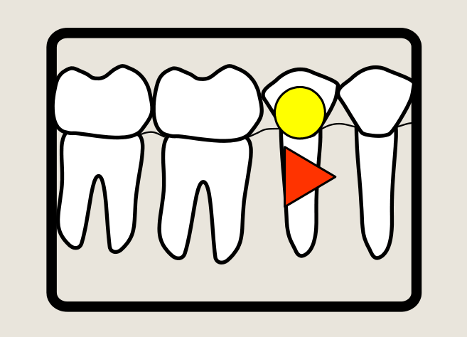
Same Lingual, Opposite Buccal (SLOB rule or Clark’s Rule)
 |  |
Horizontal Tube Shift45464748
(Normal Position)
| MESIAL |
|---|
| Lingual |
| DISTAL |
| MESIAL |
|---|
DISTAL <—> MESIAL
Right upper / maxillary periapical (paralleling technique)
DISTAL SHIFT**
MESIAL SHIFT**
MESIAL DISTAL DISTAL MESIAL Lingual Buccal
 |  |  |
 |  |  |
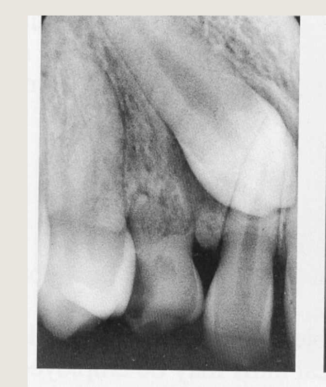 | 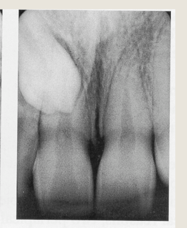 | 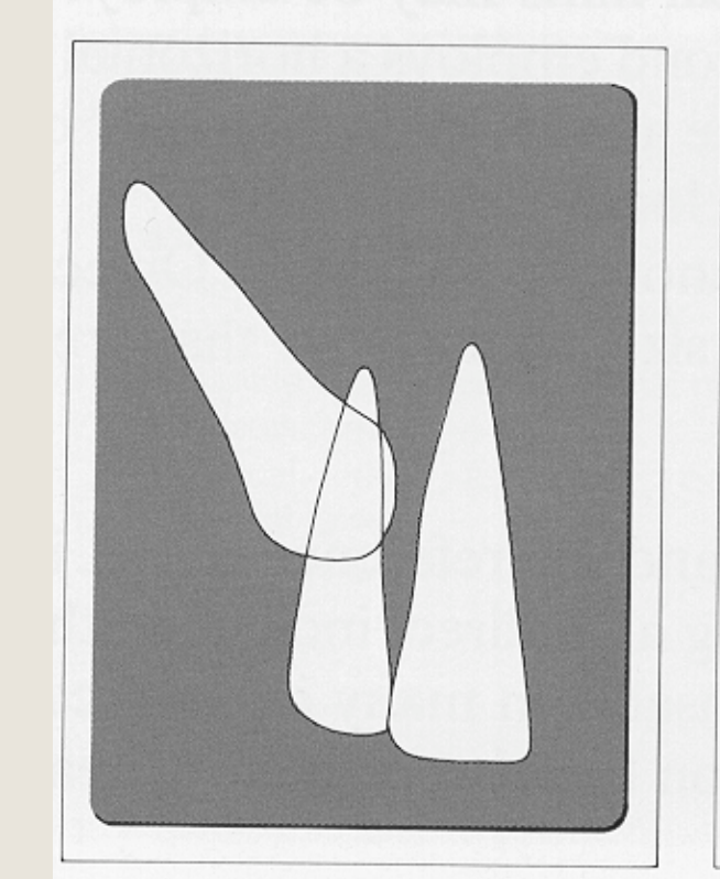 |
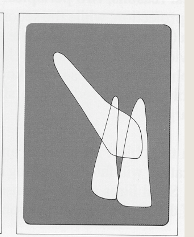 |
Vertical Tube Shift4950515253
VERTICAL TUBE SHIFT TECHNIQUE
Right lower / mandibular periapical (paralleling technique)
Increasing vertical angulation (Ascending)
Lingual Buccal
DECREASE VERTICAL ANGULATION (Descending)
Lingual Buccal
Vertical Tube Shift Technique using Occlusograph & Extra-oral Panoramic Radiograph
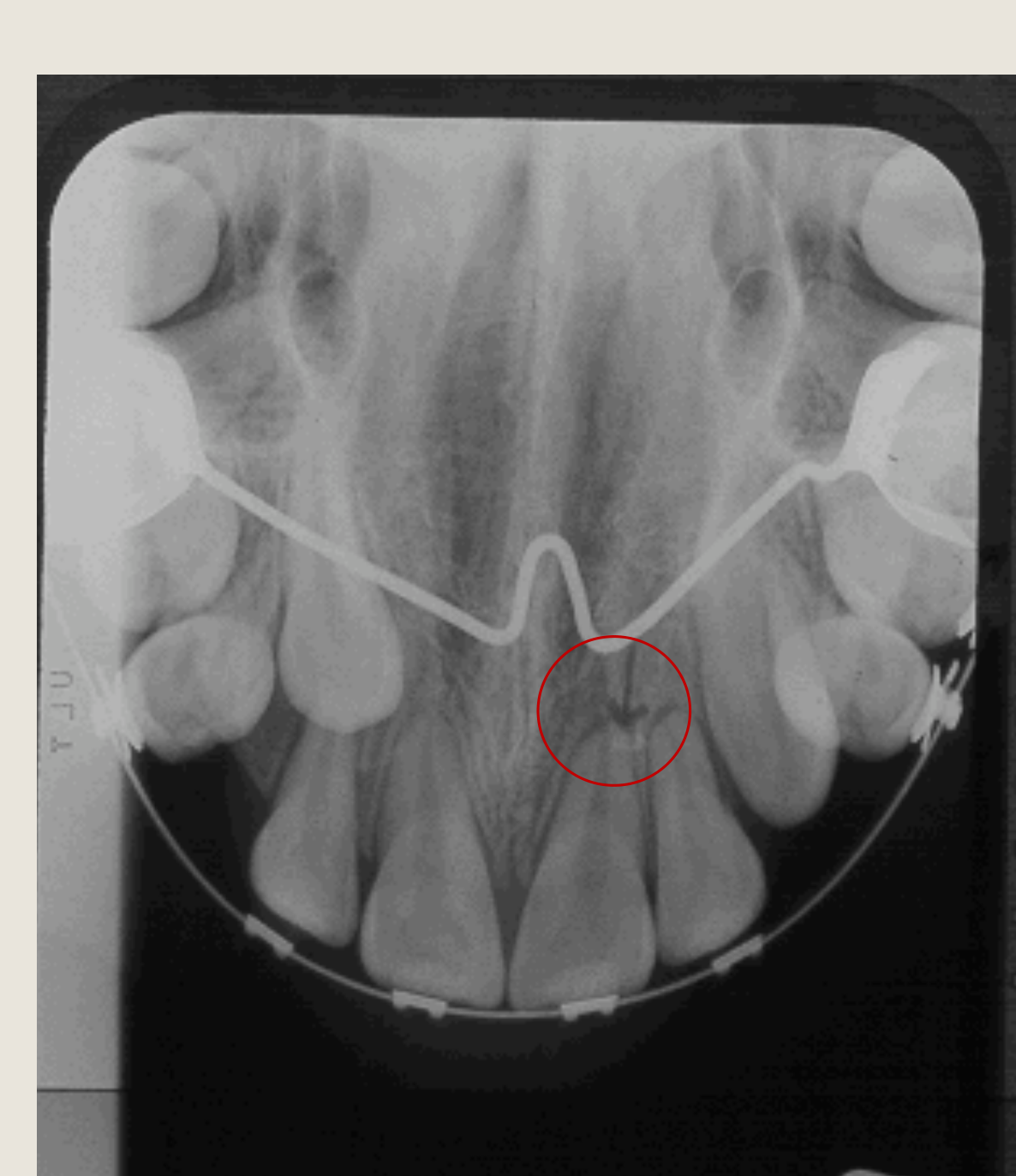
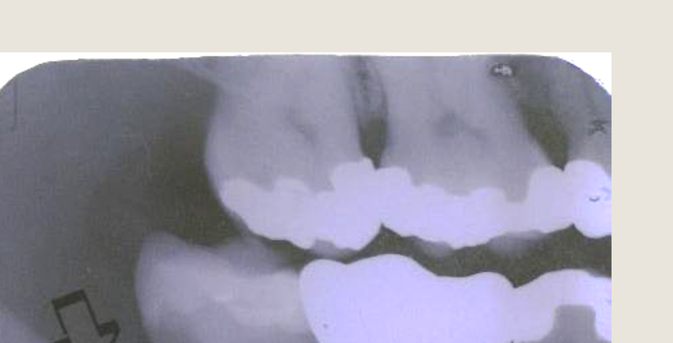
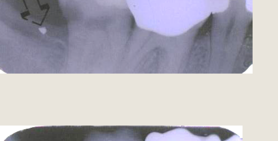
QUIZ
-
What types of I/O radiographs are these?
- Right Posterior BW + Right Upper Posterior PA
- Left Posterior BW + Left Lower Posterior PA
- Right Posterior BW + Right Lower Anterior PA
- Right Posterior BW + Right Lower Posterior PA
- Left Posterior BW + Left Upper Posterior PA
-
Which technique was used to locate the ‘radiopacity’?
- Horizontal Tube Shift
- Right Angle Technique
- Vertical Tube Shift
-
Where is the radiopacity (arrow point)?
- Lingual
- Buccal
 |  |  |
 |  |  |
 |  |  |
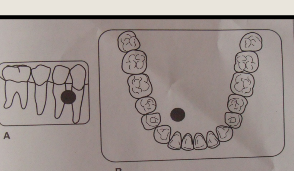
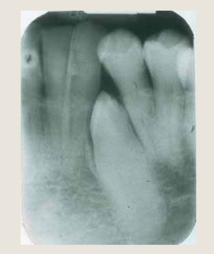
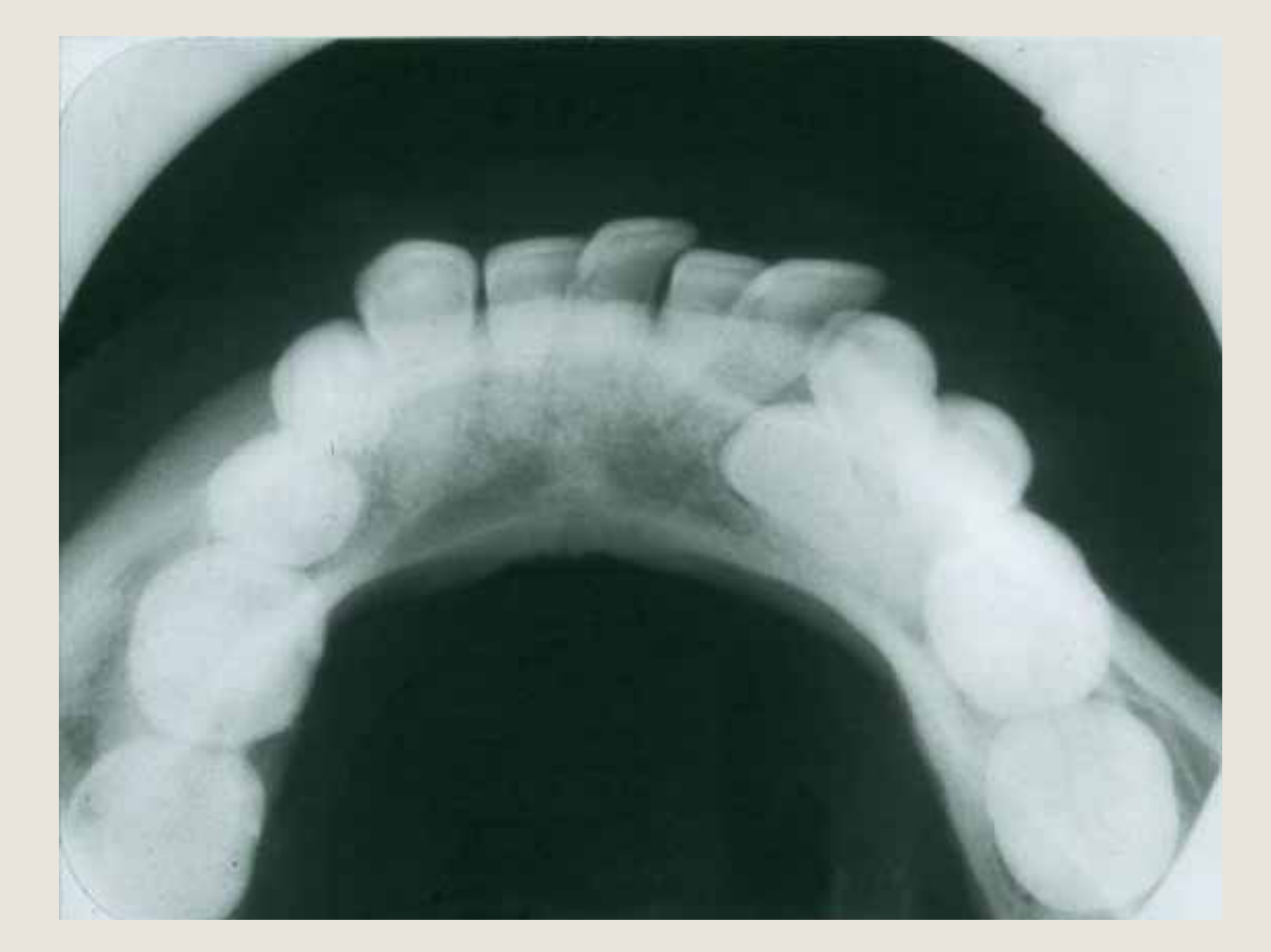
The Right Angle Technique5455
TECHNIQUES FOR LOCALIZATION
#2 - The right angle technique (Miller’s Technique)
Two radiographs are taken. The second is taken at right angles to the first.
E.g. periapical + true occlusal film
- The occlusal film will determine the bucco-lingual position of the object (Not commonly practiced)
 |  |
 |
Radiographic Errors and Film Faults
Film Faults56
- Errors in the surgery
- Errors in the darkroom (not covered in this lecture)
- Errors in film processing (not covered in this lecture)
Common Technical Errors in Surgery57
Errors in the Surgery58
- Overexposure – dark image
- Underexposure – light image
- Patient motion – blurred image
- Film exposed to white light before processing
- Analogue film or digital Photostimulable Phosphor (PSP) plate
- Not removing foreign objects such as ear-rings, spectacles, body jewellery (including tongue studs), hair clips, hearing aids, neck chains
- Poor patient positioning and incorrect technique – distorted images
- Cone-cutting
- Elongation
- Foreshortening
- Damaged Film
- Double Exposed Film
A B A B A B C D A
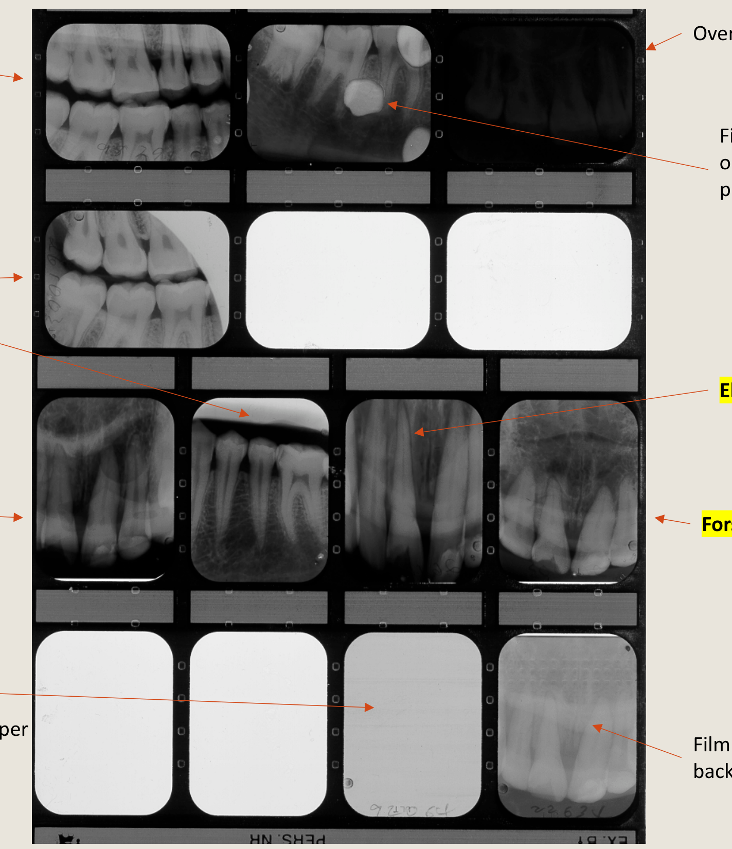
For your own learning… Identify Errors
Identification of Processing and Positioning Faults59
- Partial immersion in developer
- Over developed
- Fixer splashed on film before processing
- Cone cutting
- Elongation
- Not washing adequately post development or developer on film before processing
- Foreshortening
- Not exposed
- Left in wash over-night
- Put into fixer before developer
- Film positioned backwards
 |  |
Footnotes
-
Original PDF page 1: L2.Intraoral Radiography, p.1 ↩
-
Original PDF page 2: L2.Intraoral Radiography, p.2 ↩
-
Original PDF page 3: L2.Intraoral Radiography, p.3 ↩
-
Original PDF page 4: L2.Intraoral Radiography, p.4 ↩
-
Original PDF page 5: L2.Intraoral Radiography, p.5 ↩
-
Original PDF page 6: L2.Intraoral Radiography, p.6 ↩
-
Original PDF page 7: L2.Intraoral Radiography, p.7 ↩
-
Original PDF page 8: L2.Intraoral Radiography, p.8 ↩
-
Original PDF page 9: L2.Intraoral Radiography, p.9 ↩
-
Original PDF page 10: L2.Intraoral Radiography, p.10 ↩
-
Original PDF page 11: L2.Intraoral Radiography, p.11 ↩
-
Original PDF page 13: L2.Intraoral Radiography, p.13 ↩
-
Original PDF page 12: L2.Intraoral Radiography, p.12 ↩
-
Original PDF page 14: L2.Intraoral Radiography, p.14 ↩
-
Original PDF page 16: L2.Intraoral Radiography, p.16 ↩
-
Original PDF page 15: L2.Intraoral Radiography, p.15 ↩
-
Original PDF page 17: L2.Intraoral Radiography, p.17 ↩
-
Original PDF page 19: L2.Intraoral Radiography, p.19 ↩
-
Original PDF page 21: L2.Intraoral Radiography, p.21 ↩
-
Original PDF page 22: L2.Intraoral Radiography, p.22 ↩
-
Original PDF page 24: L2.Intraoral Radiography, p.24 ↩
-
Original PDF page 26: L2.Intraoral Radiography, p.26 ↩
-
Original PDF page 23: L2.Intraoral Radiography, p.23 ↩
-
Original PDF page 25: L2.Intraoral Radiography, p.25 ↩
-
Original PDF page 27: L2.Intraoral Radiography, p.27 ↩
-
Original PDF page 29: L2.Intraoral Radiography, p.29 ↩
-
Original PDF page 28: L2.Intraoral Radiography, p.28 ↩
-
Original PDF page 30: L2.Intraoral Radiography, p.30 ↩
-
Original PDF page 32: L2.Intraoral Radiography, p.32 ↩
-
Original PDF page 33: L2.Intraoral Radiography, p.33 ↩
-
Original PDF page 34: L2.Intraoral Radiography, p.34 ↩
-
Original PDF page 38: L2.Intraoral Radiography, p.38 ↩
-
Original PDF page 39: L2.Intraoral Radiography, p.39 ↩
-
Original PDF page 40: L2.Intraoral Radiography, p.40 ↩
-
Original PDF page 43: L2.Intraoral Radiography, p.43 ↩
-
Original PDF page 41: L2.Intraoral Radiography, p.41 ↩
-
Original PDF page 42: L2.Intraoral Radiography, p.42 ↩
-
Original PDF page 45: L2.Intraoral Radiography, p.45 ↩
-
Original PDF page 44: L2.Intraoral Radiography, p.44 ↩
-
Original PDF page 46: L2.Intraoral Radiography, p.46 ↩
-
Original PDF page 47: L2.Intraoral Radiography, p.47 ↩
-
Original PDF page 48: L2.Intraoral Radiography, p.48 ↩
-
Original PDF page 49: L2.Intraoral Radiography, p.49 ↩
-
Original PDF page 50: L2.Intraoral Radiography, p.50 ↩
-
Original PDF page 51: L2.Intraoral Radiography, p.51 ↩
-
Original PDF page 52: L2.Intraoral Radiography, p.52 ↩
-
Original PDF page 53: L2.Intraoral Radiography, p.53 ↩
-
Original PDF page 54: L2.Intraoral Radiography, p.54 ↩
-
Original PDF page 55: L2.Intraoral Radiography, p.55 ↩
-
Original PDF page 56: L2.Intraoral Radiography, p.56 ↩
-
Original PDF page 57: L2.Intraoral Radiography, p.57 ↩
-
Original PDF page 58: L2.Intraoral Radiography, p.58 ↩
-
Original PDF page 59: L2.Intraoral Radiography, p.59 ↩
-
Original PDF page 60: L2.Intraoral Radiography, p.60 ↩
-
Original PDF page 61: L2.Intraoral Radiography, p.61 ↩
-
Original PDF page 62: L2.Intraoral Radiography, p.62 ↩
-
Original PDF page 64: L2.Intraoral Radiography, p.64 ↩
-
Original PDF page 63: L2.Intraoral Radiography, p.63 ↩
-
Original PDF page 65: L2.Intraoral Radiography, p.65 ↩