Introduction To Digital Imaging In Dentistry1

Learning Objectives2
- Understand differences between analogue and digital imaging
- Know different types of imaging sensors
- What are advantages & disadvantages of digital imaging?

Recommended Textbooks3
- Essentials of dental radiography and radiology 5th edition by Whaites, Eric; Drage, Nicholas; Churchill Livingstone 2013
- Pocket atlas of dental radiology by Pasler, Friedrich A; Visser, Heiko; Flexibook, 2007
- Oral radiology: principles and interpretation 7th edition by White, Stuart C; Pharoah, M. J; Permalink 2014
- 8th edition available now
Comparison Of Analogue And Digital Systems
Film vs Digital Receptors4
Processing
- Chemical vs Electronic, time, health & safety, …
Storage & Transfer
Image display
Image resolution
- Analogue = continuous density spectrum
- Digital = numeric format of the image content and its discreteness
- Pixels
- At each pixel of an electronic detector, the absorption of x-rays generates a small voltage
Dosage
Others
- Cost, image enhancement, etc.
Digital Image Fundamentals And Pixels5
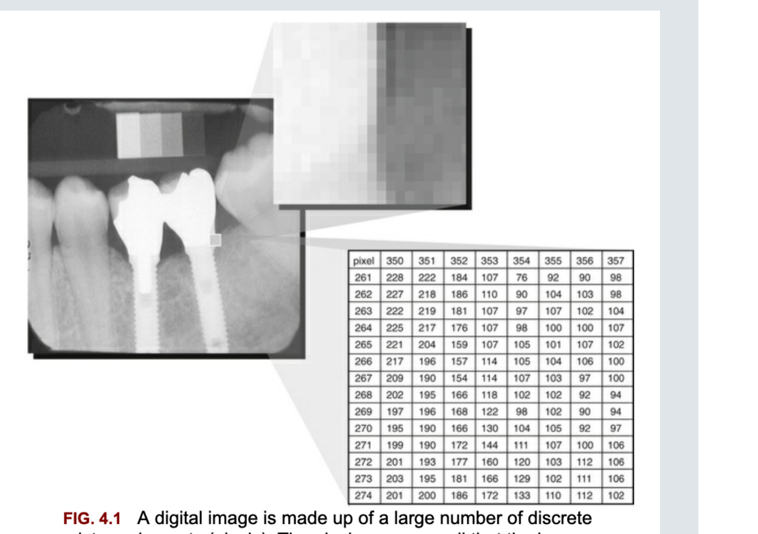
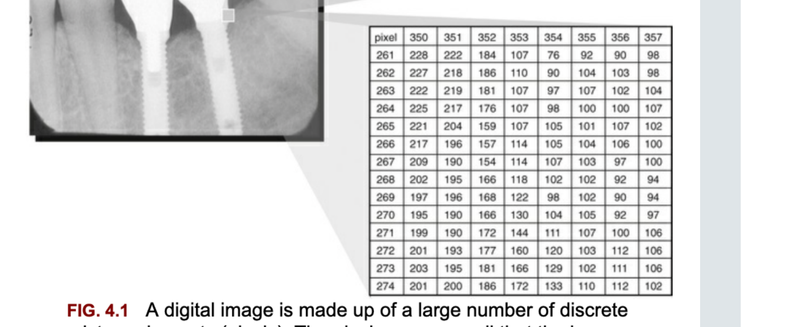
FIG. 4.1 A digital image is made up of a large number of discrete picture elements (pixels). The pixels are so small that the image appears smooth at normal magnification. The location of each pixel is uniquely identified by row and column coordinates within the image matrix. The value assigned to a pixel represents the intensity (gray level) of the image at that location.
| pixel | 350 | 351 | 352 | 353 | 354 | 355 | 356 | 357 |
|---|---|---|---|---|---|---|---|---|
| 261 | 228 | 222 | 184 | 107 | 76 | 92 | 90 | 98 |
| 262 | 227 | 218 | 186 | 110 | 90 | 104 | 103 | 98 |
| 263 | 222 | 219 | 181 | 107 | 97 | 107 | 102 | 104 |
| 264 | 225 | 217 | 176 | 107 | 98 | 100 | 100 | 107 |
| 265 | 221 | 204 | 159 | 107 | 105 | 101 | 107 | 102 |
| 266 | 217 | 196 | 157 | 114 | 105 | 104 | 106 | 100 |
| 267 | 209 | 190 | 154 | 114 | 107 | 103 | 97 | 100 |
| 268 | 202 | 195 | 166 | 118 | 102 | 102 | 92 | 94 |
| 269 | 197 | 196 | 168 | 122 | 98 | 102 | 90 | 94 |
| 270 | 195 | 190 | 166 | 130 | 104 | 105 | 92 | 97 |
| 271 | 199 | 190 | 172 | 144 | 111 | 107 | 100 | 106 |
| 272 | 201 | 193 | 177 | 160 | 120 | 103 | 112 | 106 |
| 273 | 203 | 195 | 181 | 166 | 129 | 102 | 111 | 106 |
| 274 | 201 | 200 | 186 | 172 | 133 | 110 | 112 | 102 |
 |  |
Analog To Digital Conversion Process6
 |  |
Analog-to-Digital Conversion (ADC)7
- Ie. From photons/voltages to digital Image
- Involves TWO steps
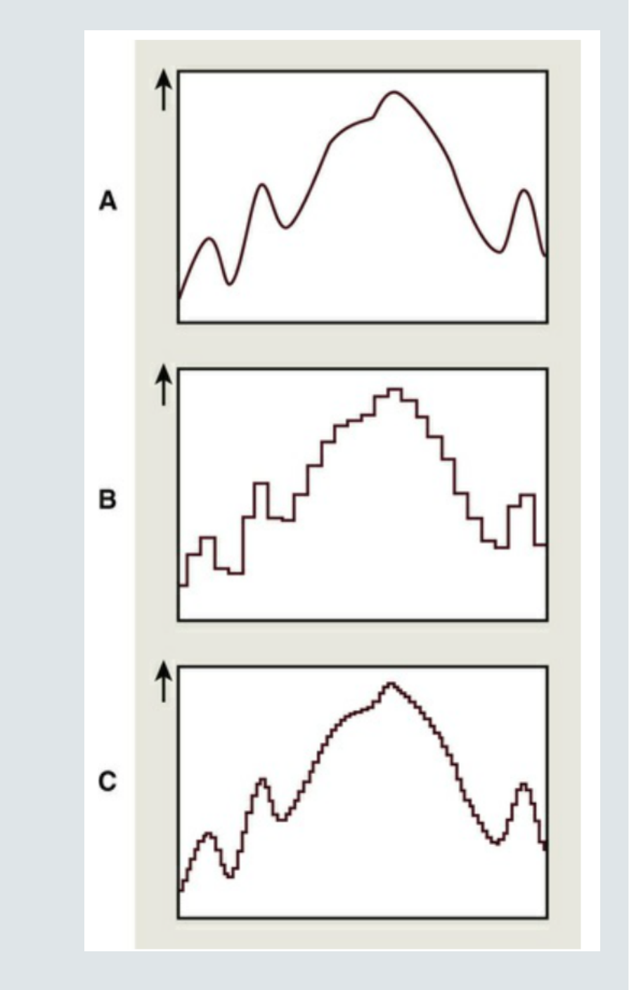
- Sampling
- A range of voltages are grouped together
- Quantisation
- Each sampled range is assigned a grey value
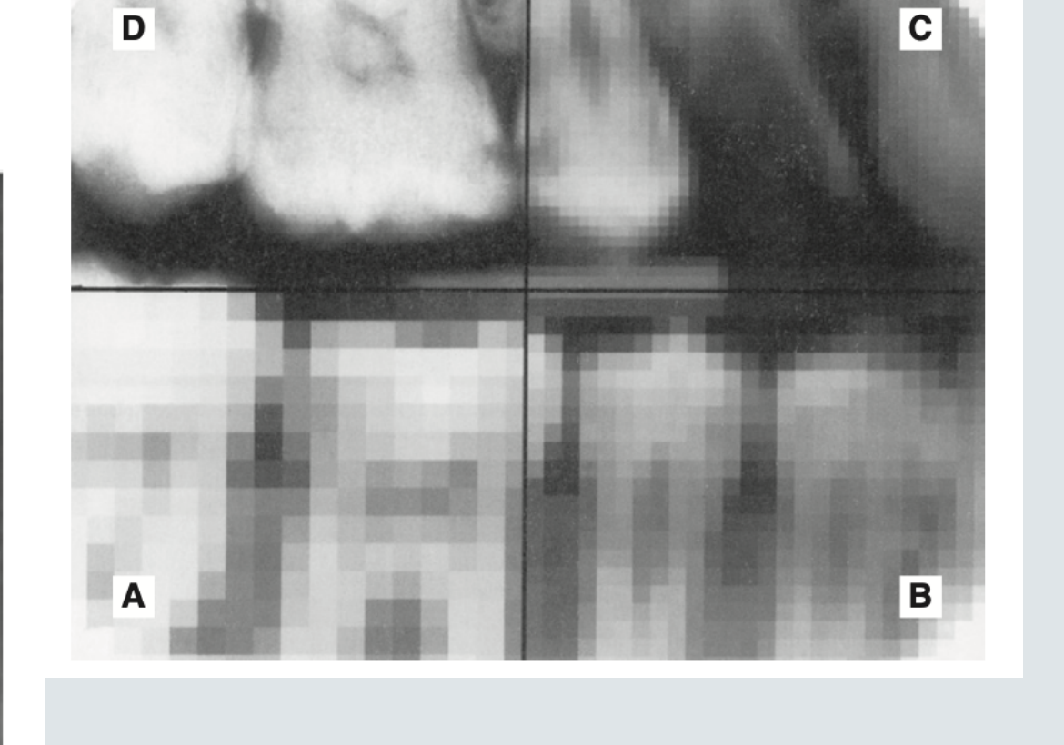
- Sampling
- Large sampling = ‘pixelated’ image ‘B’
- Narrow sampling = close to original signal ‘C’
1 2 3 4 5 6 7 8

8 pixel numbers

8 shades of grey

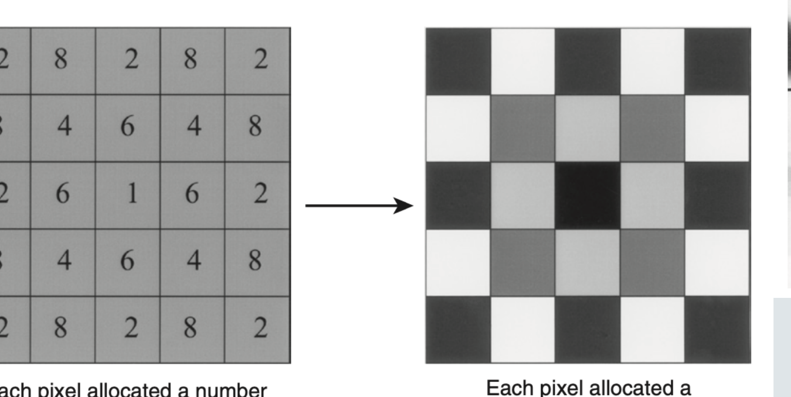
2 8 2 8 2
8 4 6 4 8
2 6 1 6 2
8 4 6 4 8
2 8 2 8 2

Each pixel allocated a number

Each pixel allocated a shade of grey

A B
C D
Digital Image Receptors8
- Two types
- Solid-state detectors / sensors
- Charged-coupled device (CCD)
- Complementary metal oxide semiconductors (CMOS)
- Flat panel detectors → extra-oral use
- Photostimulable phosphor (PSP) plates
- Solid-state detectors / sensors
Solid State Detectors
CCD9
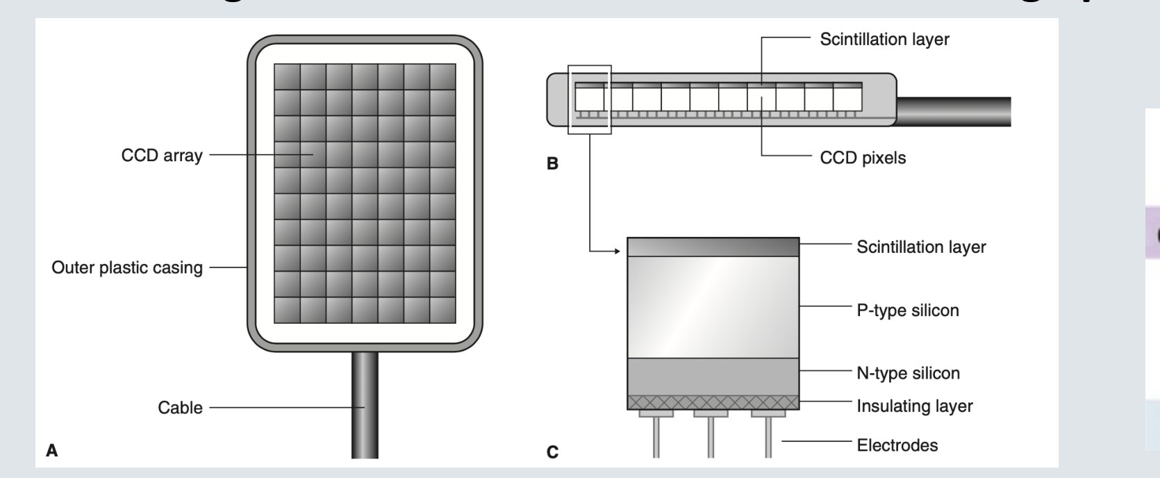
- charge-coupled device
- first digital image receptor to be adapted for intraoral imaging
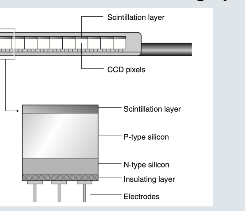
- thin wafer of silicon pixels consisting of n-type silicon and p-type silicon covered with a scintillation layer
- Light and silicon interaction creates charge packet for each pixel (latent image)
A
B
C
Scintillation layer
CCD pixels
Scintillation layer
P-type silicon
N-type silicon
Insulating layer
Electrodes
 |  |
 |
Charge Coupled Device Technology
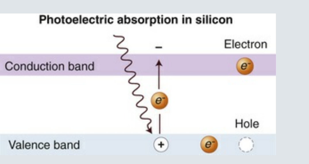
Photoelectric absorption in silicon:
Conduction band
-
Electron
e⁻
Hole
Valence band
+
e⁻
CCD Image Read-out
- “bucket brigade”
- As a charge reaches the end of its row, it is transferred to a readout amplifier and transmitted as a voltage to the ADC located within or connected to the computer
Complementary Metal Oxide Semiconductor Technology
CMOS (Complementary Metal Oxide Semiconductor) X-ray Detector
Explosion View of CMOS Sensor
Components:
- Back Housing + Cable
- Electronic Substrate
- CMOS Imaging Chip
- Fiber-optic Face Plate
- Scintillator Screen
- Front Housing
Direction of X-ray Beam:
CMOS Image Read-out
- CCD
- CMOS
- Photon to electron conversion
- Conversion: Charge to electrical signal
- Two different principles: CCD vs CMOS
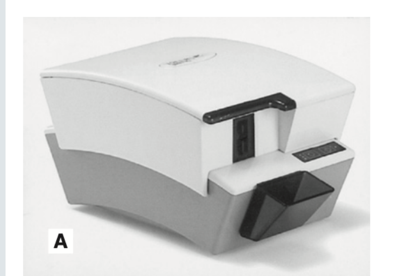
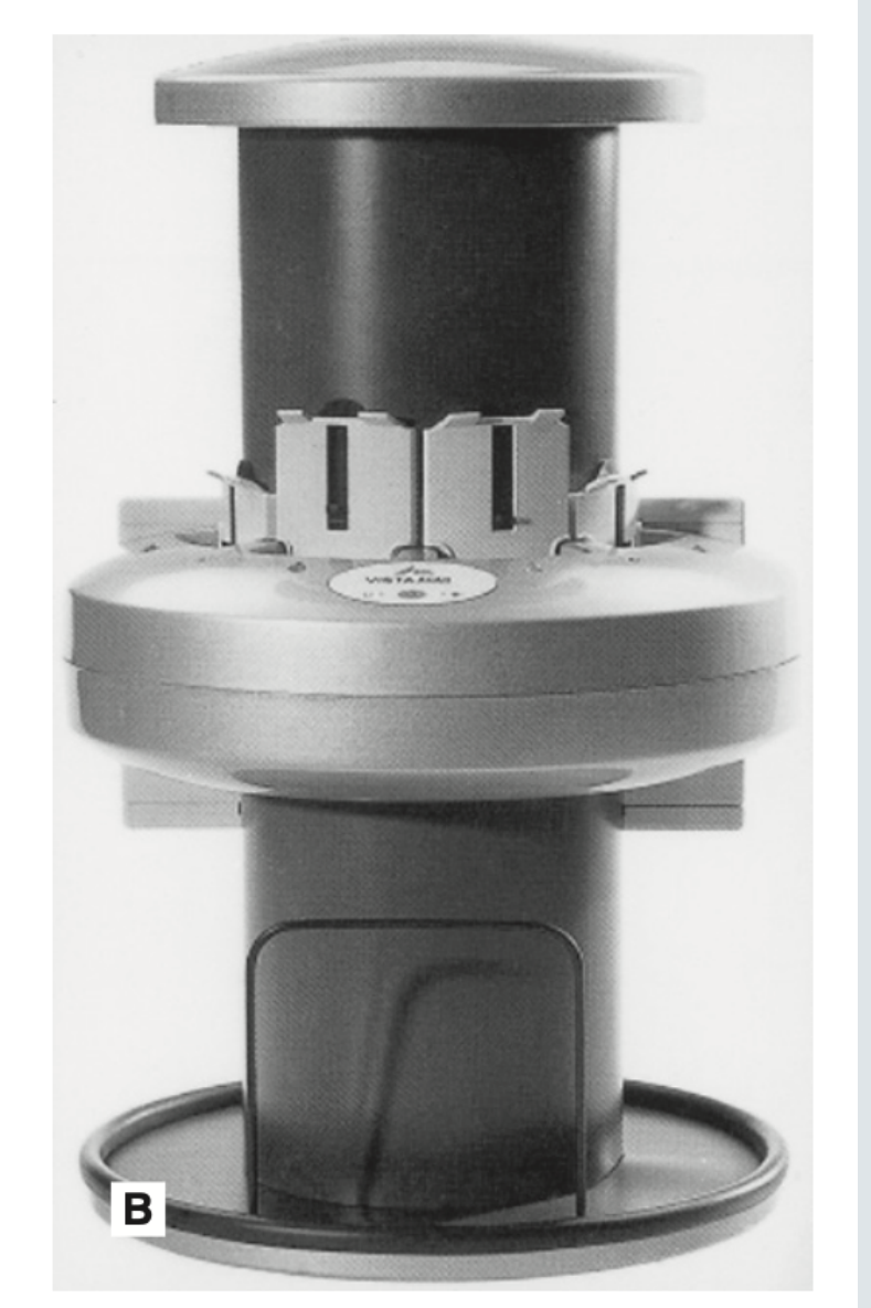
Photostimulable Phosphor Plates10
 |  |
PSP11
- Photostimulable Phosphor
- Europium-doped barium fluorohalide
- Image processing is NOT instant
- Absorb and store energy from x-rays → latent image
- Release this energy as light (phosphorescence) when stimulated by another light of an appropriate wavelength (= scanner)
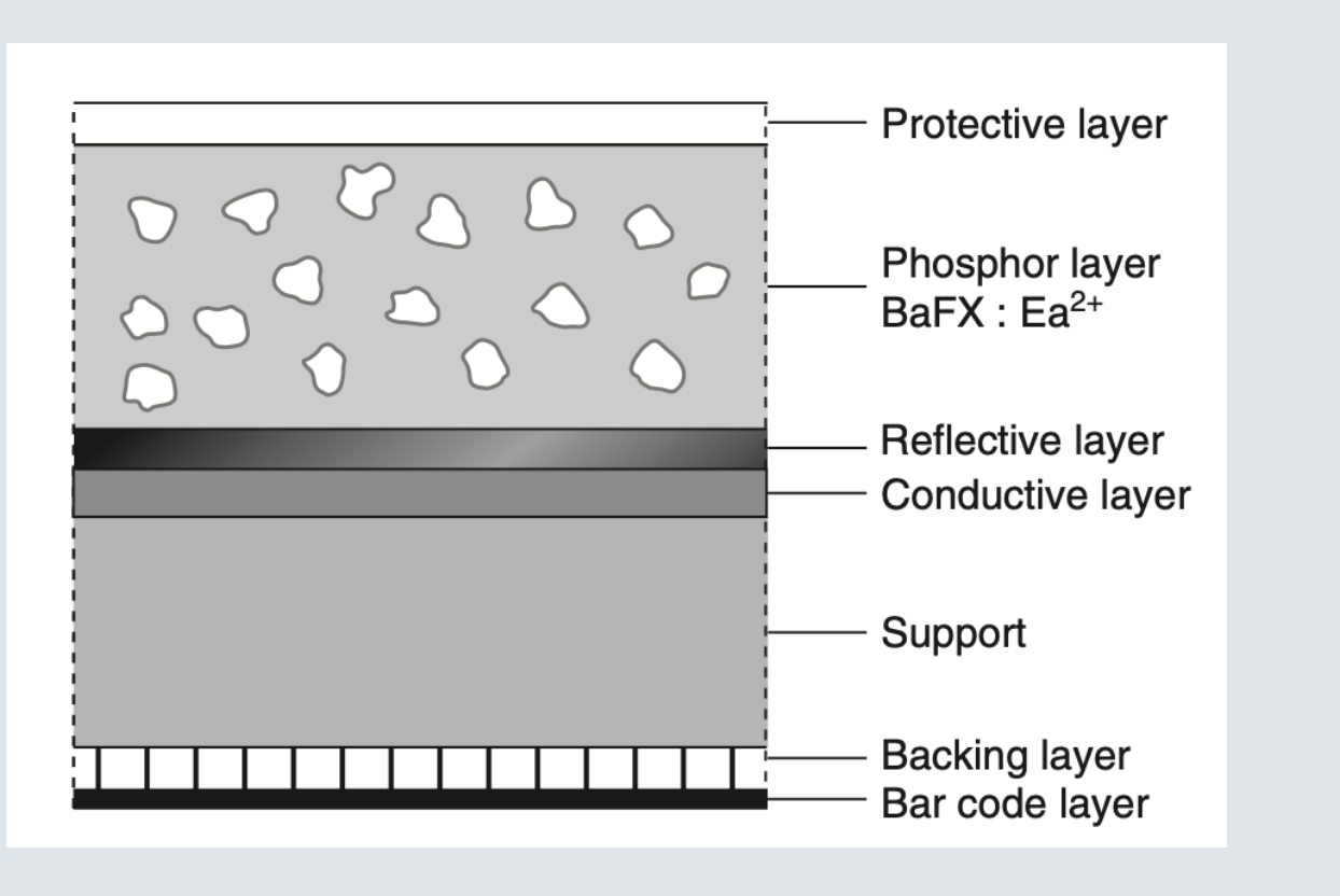
Image Quality And Resolution
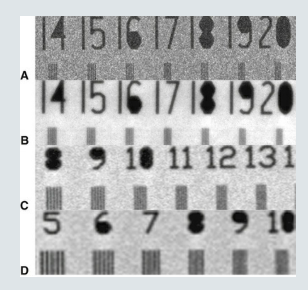
- Capacity for distinguishing fine detail in an image
- Measured and reported in units of line pairs per millimeter
- Eyes can detect 6 lp/mm.
- Film > 20 lp/mm
- SSD ~ 20 lp/mm
- PSP ~ 10 lp/mm
- The smaller the size of the pixel, the higher the maximally attainable resolution
Spatial Resolution12
Contrast Resolution13
- Ability to distinguish different densities in the radiographic image
- Current digital detectors capture data at 8, 10, 12, or 16 bits.
- Conventional computer monitors are capable of displaying a grey scale of only 8 bits (2^8 = 256 shades of grey)
- The human eyes in darkroom / reporting room are capable of distinguishing 60 grey levels
- Less than 30 grey levels in operatory dental clinics

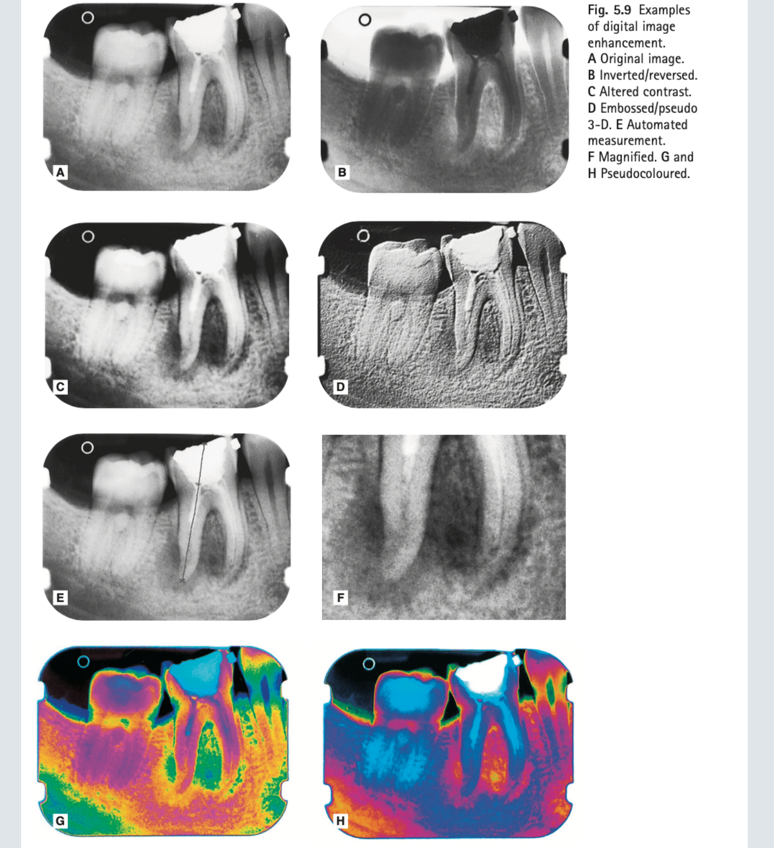
Image Manipulation And Enhancement1415
- Magnification
- Brightness
- Contrast
- Inversion
- Sharpening
- Smoothing
5.9 Examples of digital image enhancement.
- A Original image.
- B Inverted/reversed.
- C Altered contrast.
- D Embossed/pseudo 3-D.
- E Automated measurement.
- F Magnified.
- G and H Pseudocoloured.
Clinical Comparison Of Solid State Detectors And Phosphor Plates1617
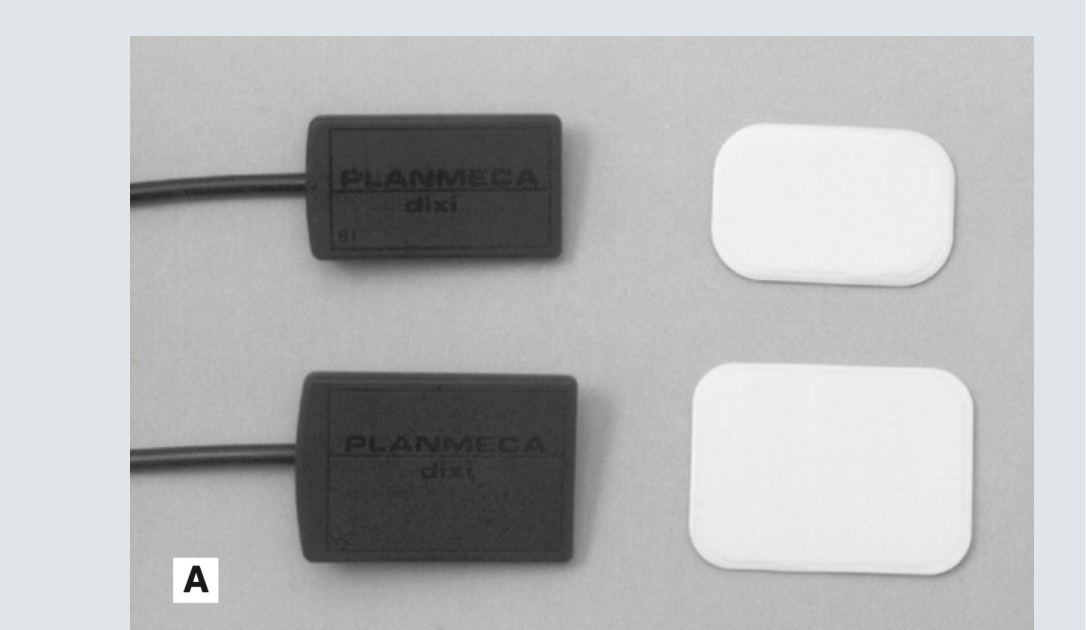
- SSD vs PSP (clinical factors)
- Patient comfort
- Intraoral SSDs are bulky (5-7mm) & often corded
- PSPs are similar to films – flexible and thin
- Intra-oral holders
- SSD holders are different
- Exposure
- Computer & software must be ready before exposure
- Processing
- SSDs are immediate
- PSPs need a scanner
- Sterilisation
END.
Footnotes
-
Original PDF page 1: L4 Digital Imaging, p.1 ↩
-
Original PDF page 2: L4 Digital Imaging, p.2 ↩
-
Original PDF page 3: L4 Digital Imaging, p.3 ↩
-
Original PDF page 4: L4 Digital Imaging, p.4 ↩
-
Original PDF page 5: L4 Digital Imaging, p.5 ↩
-
Original PDF page 7: L4 Digital Imaging, p.7 ↩
-
Original PDF page 6: L4 Digital Imaging, p.6 ↩
-
Original PDF page 8: L4 Digital Imaging, p.8 ↩
-
Original PDF page 9: L4 Digital Imaging, p.9 ↩
-
Original PDF page 14: L4 Digital Imaging, p.14 ↩
-
Original PDF page 13: L4 Digital Imaging, p.13 ↩
-
Original PDF page 15: L4 Digital Imaging, p.15 ↩
-
Original PDF page 16: L4 Digital Imaging, p.16 ↩
-
Original PDF page 17: L4 Digital Imaging, p.17 ↩
-
Original PDF page 18: L4 Digital Imaging, p.18 ↩
-
Original PDF page 19: L4 Digital Imaging, p.19 ↩
-
Original PDF page 20: L4 Digital Imaging, p.20 ↩