Panoramic Radiography1
- Revise panoramic radiographic anatomy and artifacts.
- Review indications for panoramic imaging.
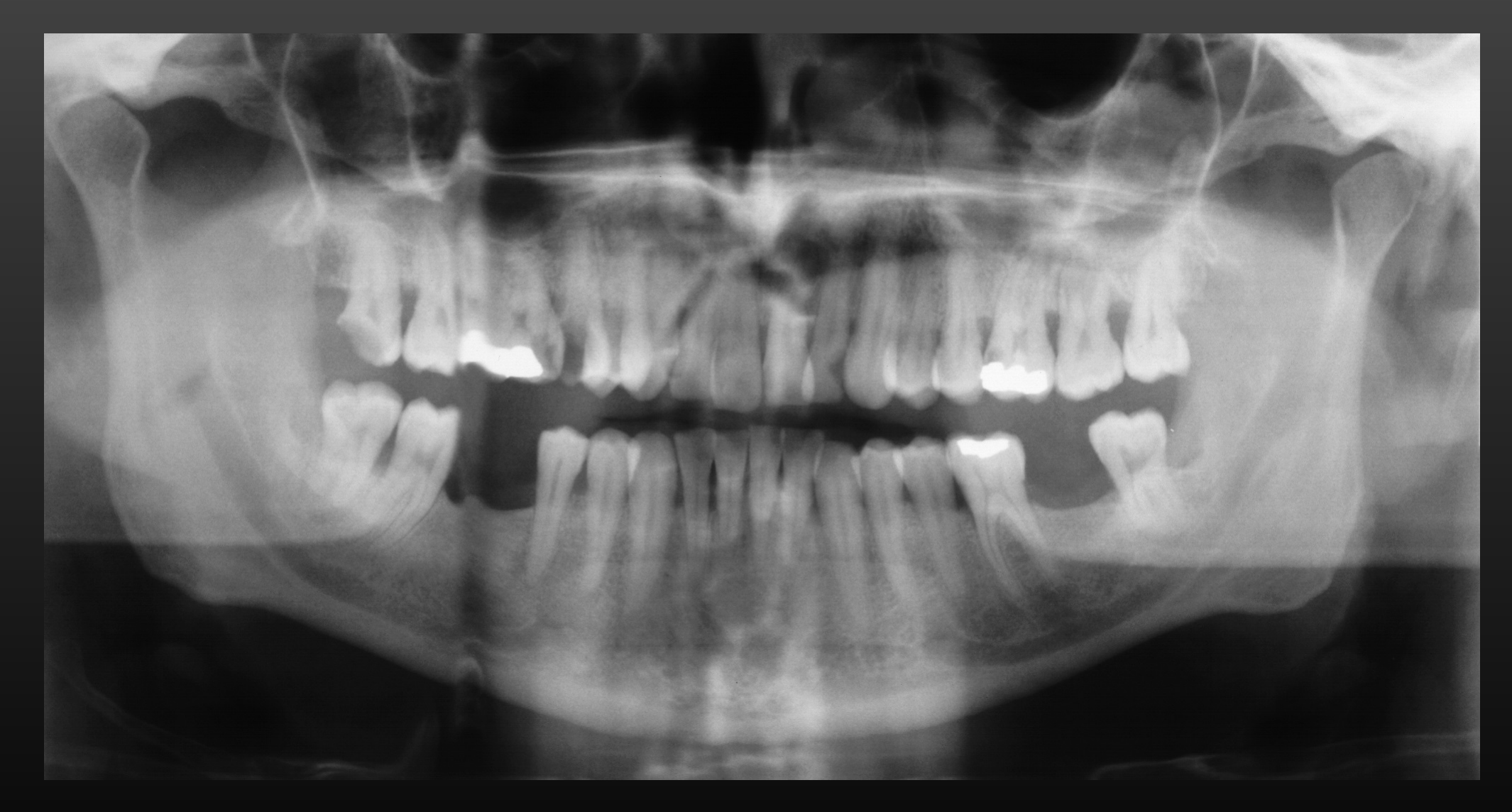
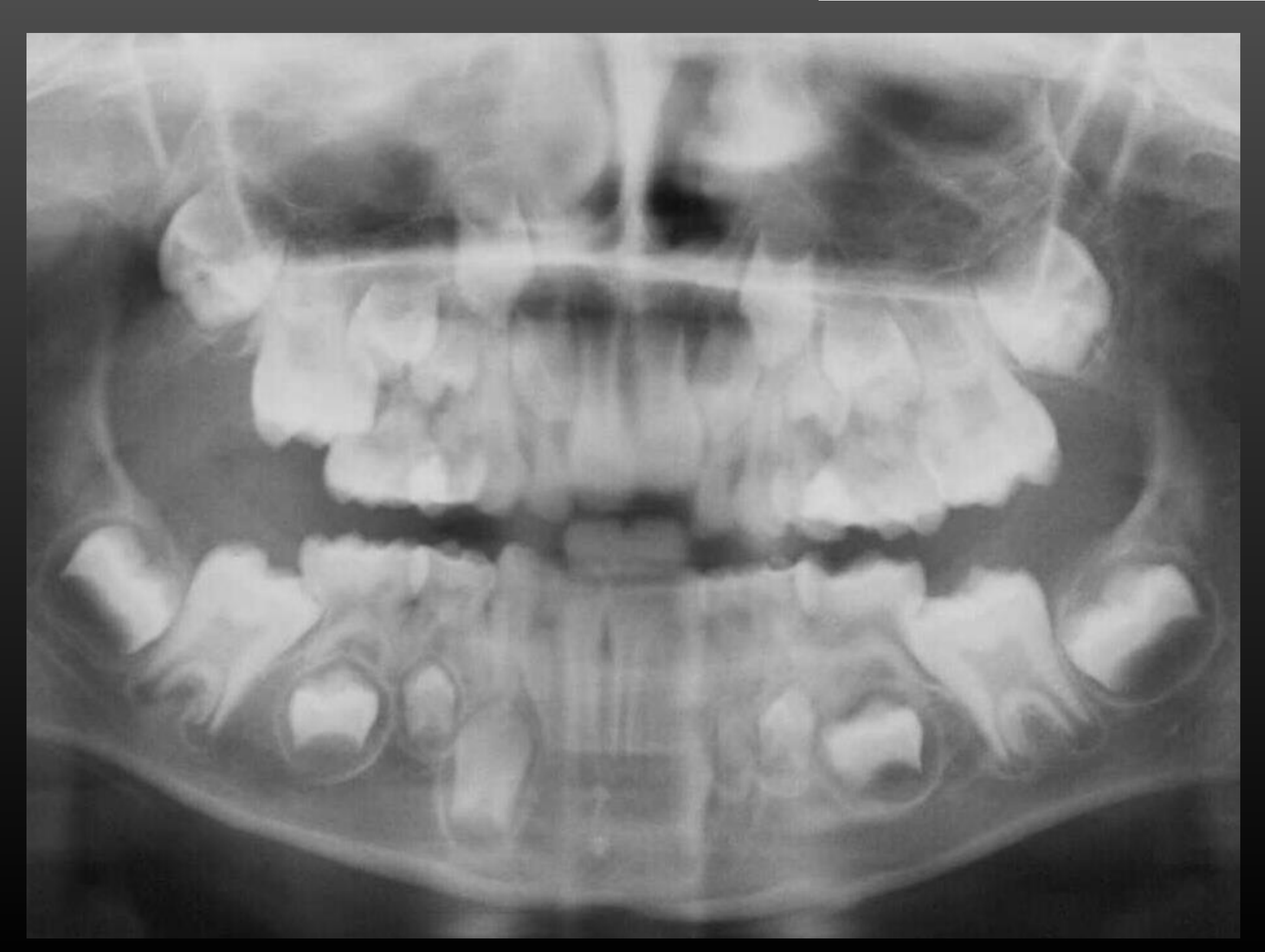
- Perform basic OPG interpretation, focusing on dentoalveolar findings (caries, periodontal bone loss, and mixed dentition).
Introduction and Learning Objectives
Learning Objectives2
- What is panoramic radiography (PR)?
- What are the components of an extra-oral film cassette?
- What are intensifying screens?
- What is focal trough?
- Understanding correct PR techniques
- How are artefacts produced?
- Understanding PR Anatomy
- What are the indications for panoramic imaging?

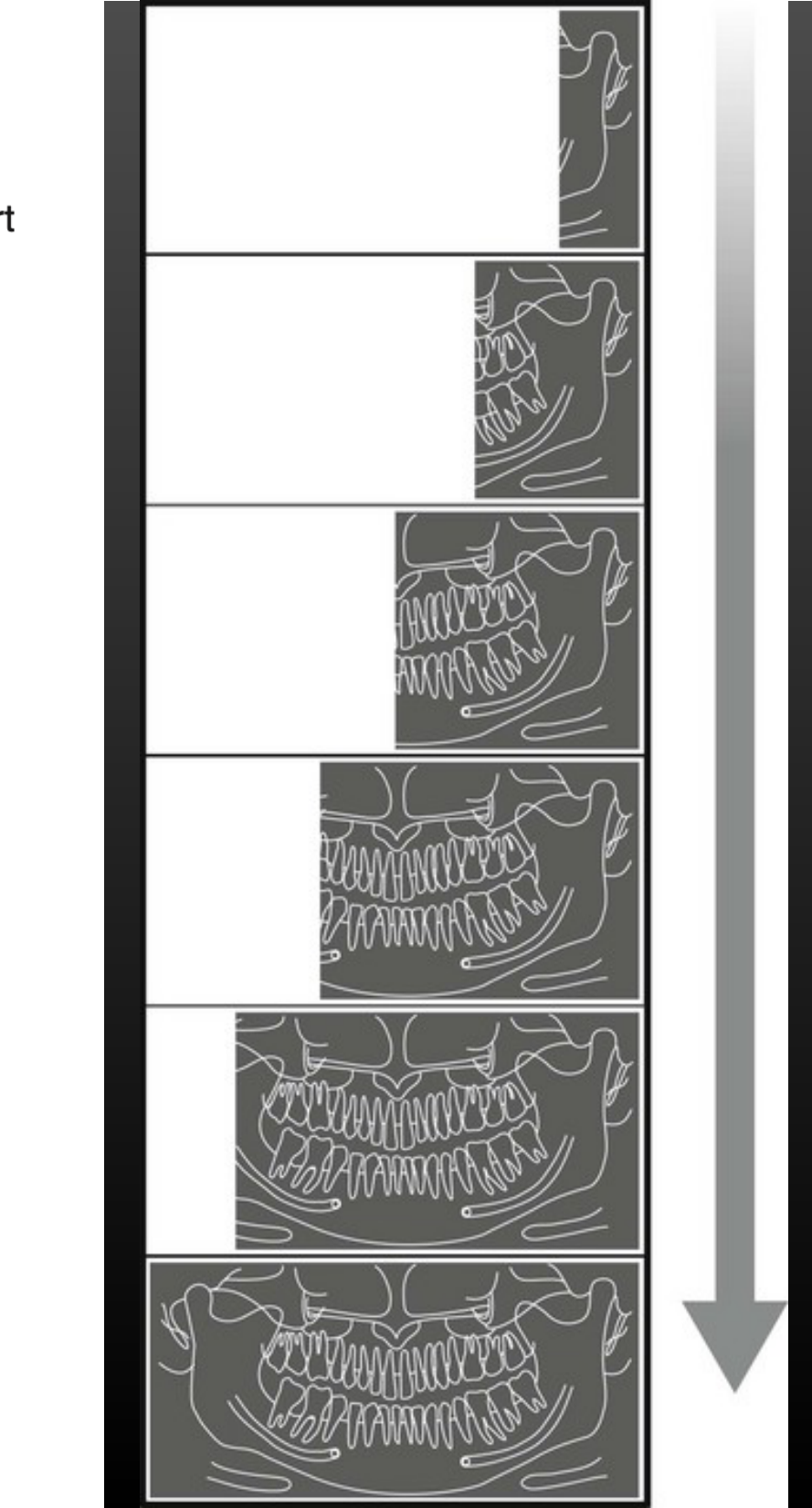
Panoramic Imaging3
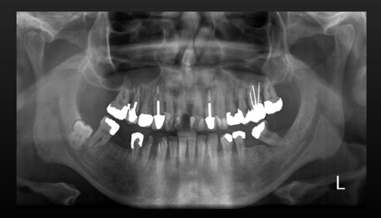
- AKA OPG (orthopantomogram)
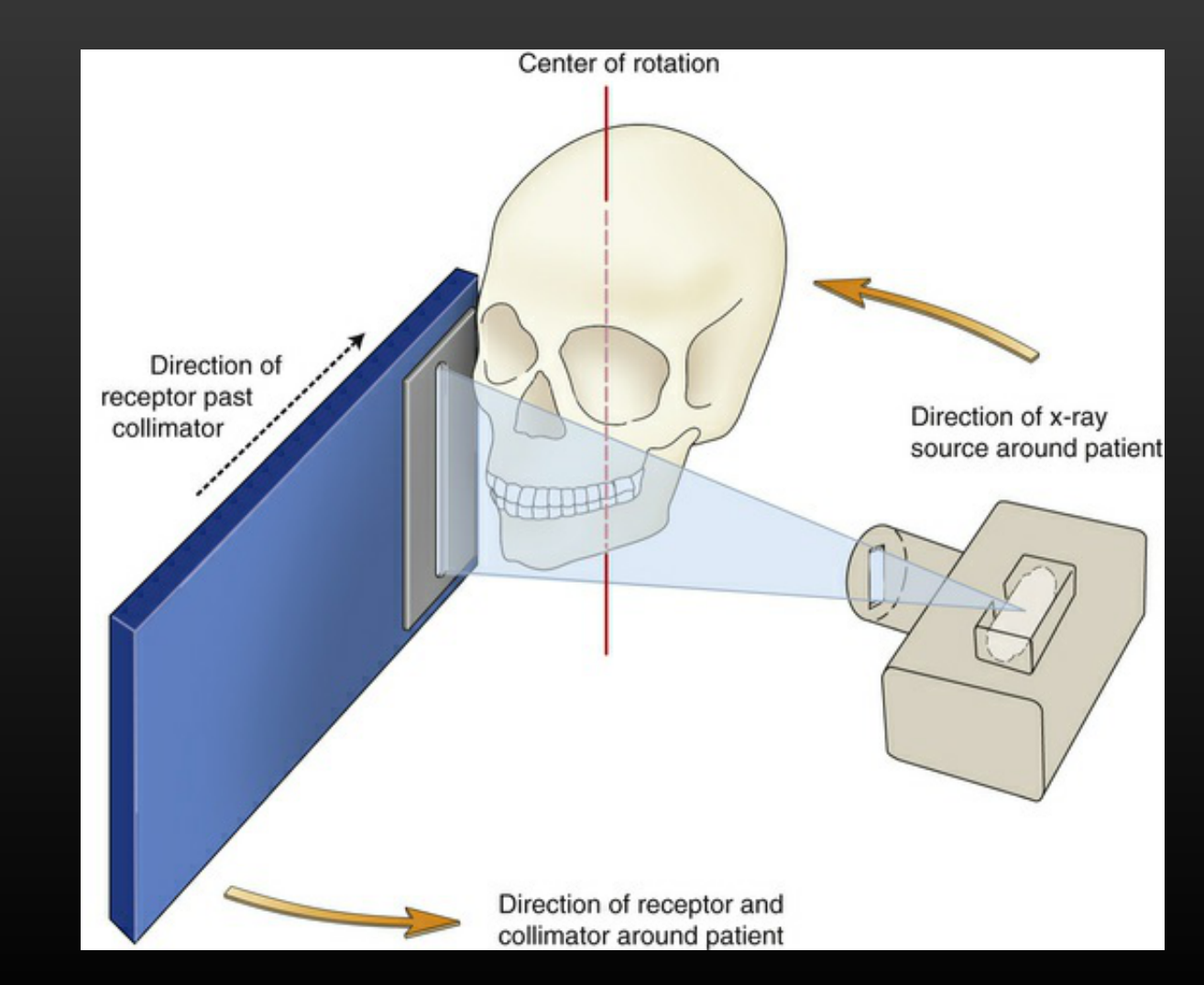
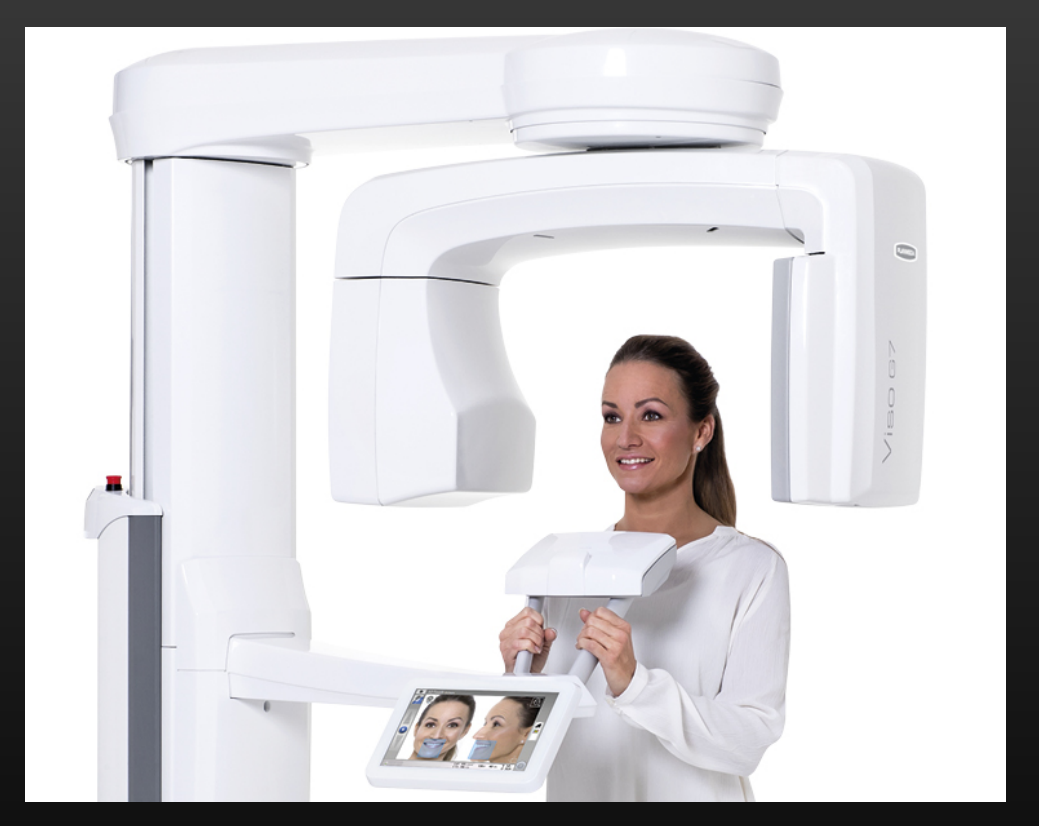
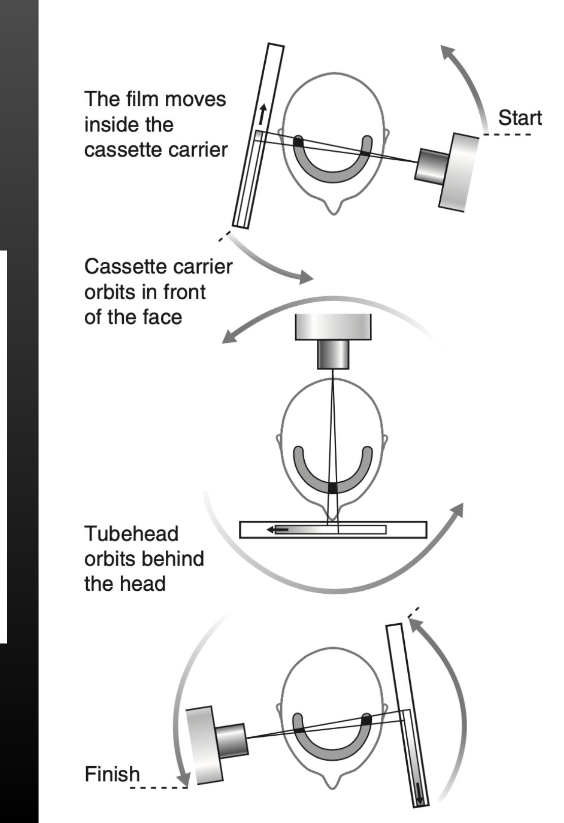
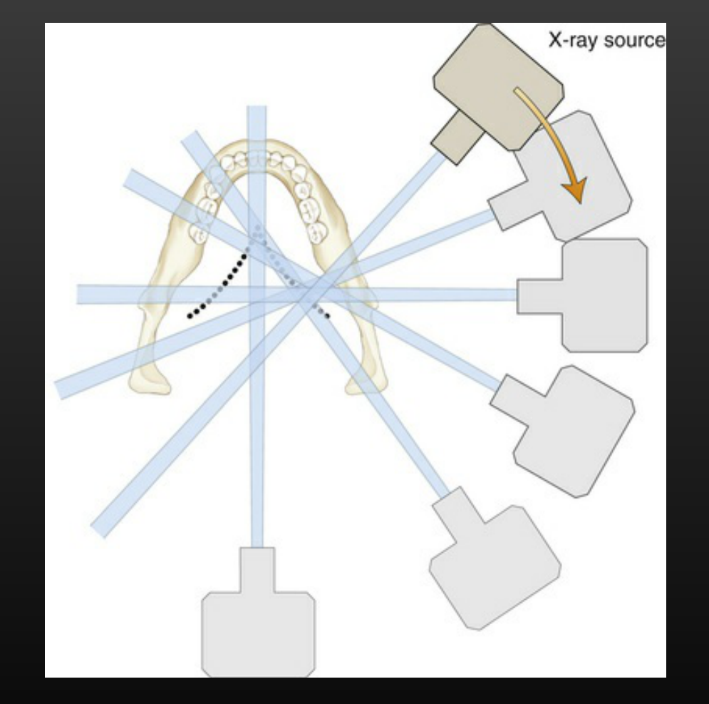
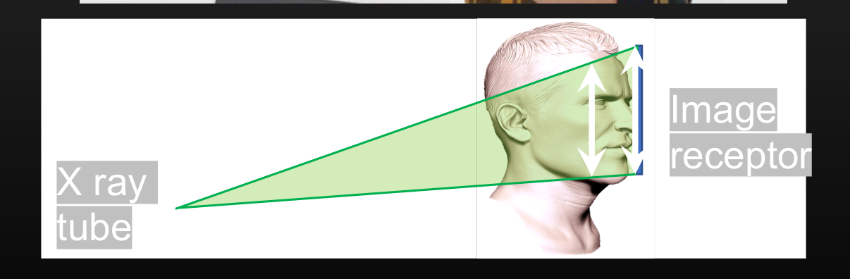
- Tomographic image of maxillofacial structures using a rotating x-ray source & receptor
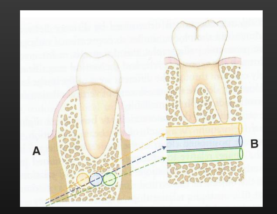
- OPGs are two-dimensional images of three-dimensional structures.
- They are easily accessible, relatively cheap, and low dose (equivalent to approximately two to three bitewings).
- OPGs have poor spatial resolution (less than 10 line pairs per millimeter) compared to intraoral systems (around 20 line pairs per millimeter).
- This makes them less effective for detecting fine caries but suitable for gross lesions.
- OPGs can be less technique-sensitive than intraoral films for patients with strong gag reflexes or pediatric patients who move during film placement.
 |  |
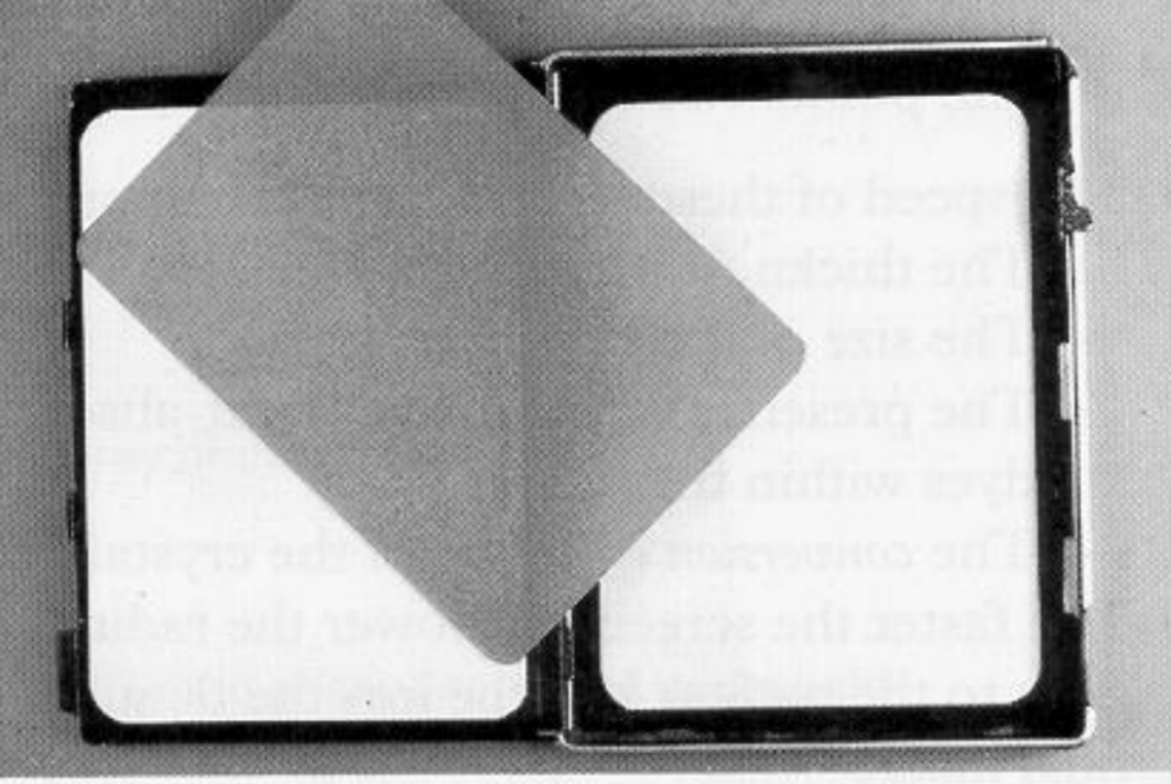
Film Cassette Components4
 |  |
 |
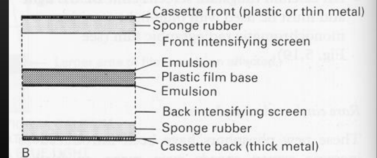
Cassette Structure and Layers5
A B
- Cassette front (plastic or thin metal)
- Sponge rubber
- Front intensifying screen
- Emulsion
- Plastic film base
- Emulsion
- Back intensifying screen
- Sponge rubber
- Cassette back (thick metal)
Fig. 5.21A A standard 18 × 13 cm cassette opened up showing the white intensifying screens and the film.
 |  |
Emulsion and Intensifying Screens
Emulsion Layer6
- Light-sensitive silver halide crystals coated onto both sides of a transparent base material.
- Double sided films have increased optical density.
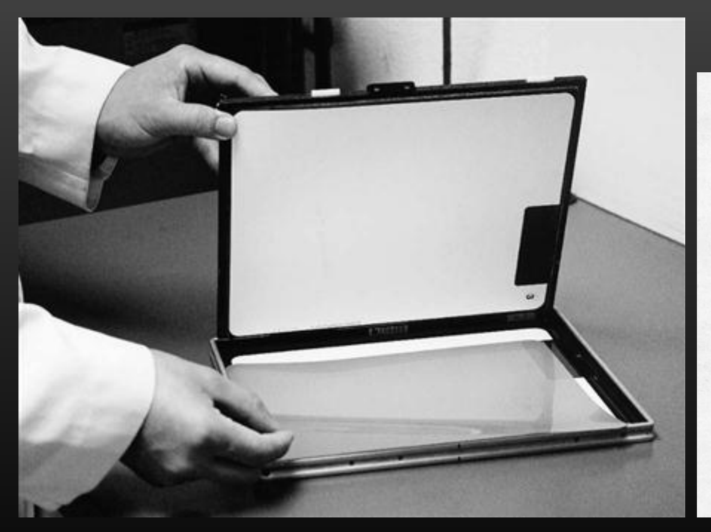 | 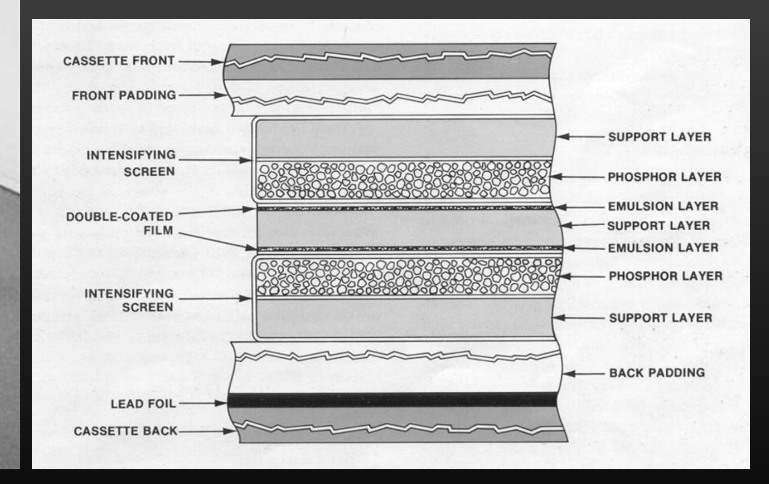 |
Layered Structure
- CASSETTE FRONT
- FRONT PADDING
- INTENSIFYING SCREEN
- DOUBLE-COATED FILM
- SUPPORT LAYER
- EMULSION LAYER
- SUPPORT LAYER
- EMULSION LAYER
- INTENSIFYING SCREEN
- LEAD FOIL
- CASSETTE BACK
- BACK PADDING
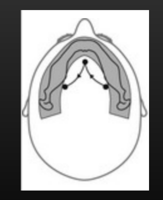
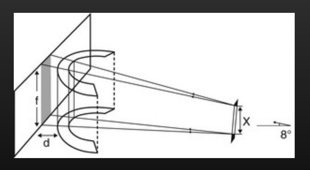
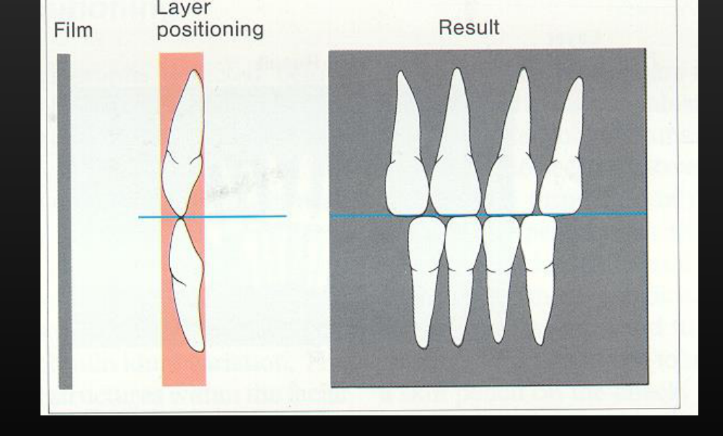
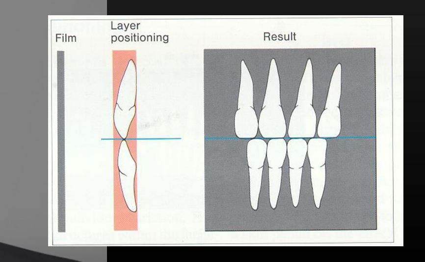
Focal Trough and Image Layer78910
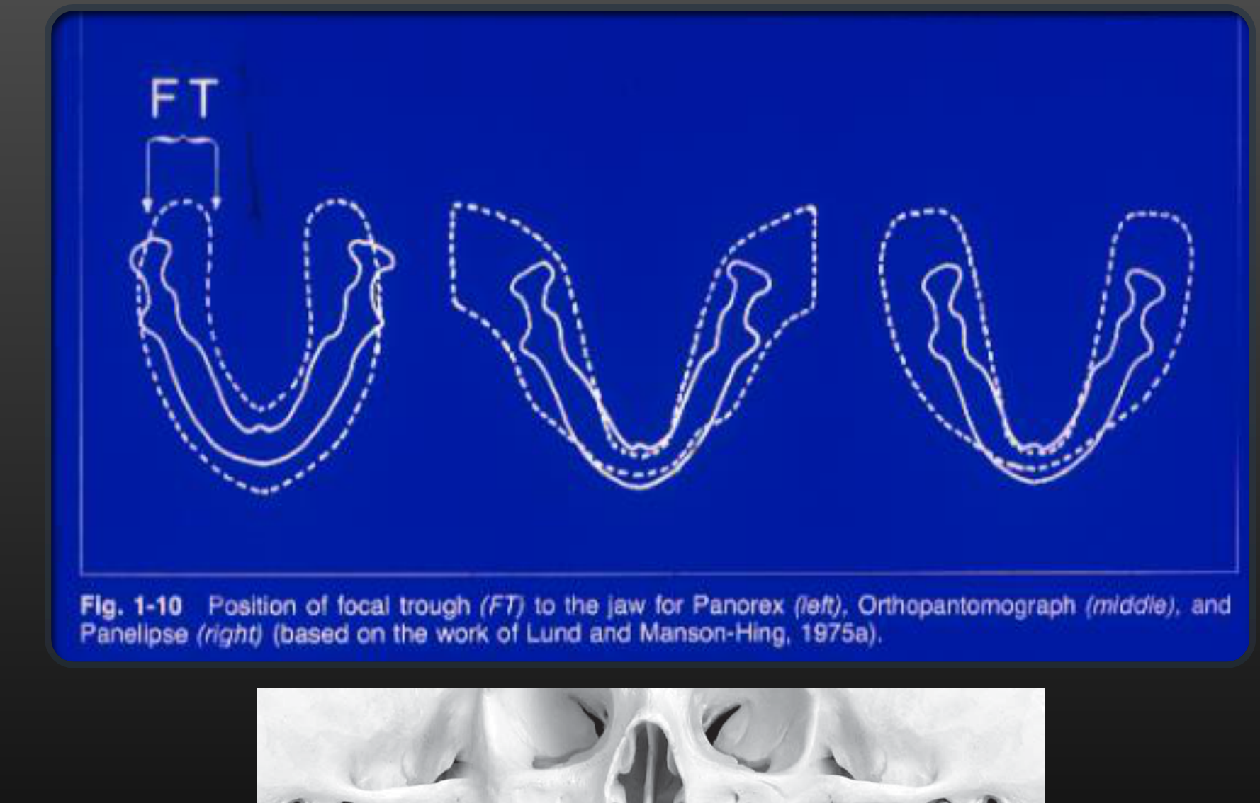
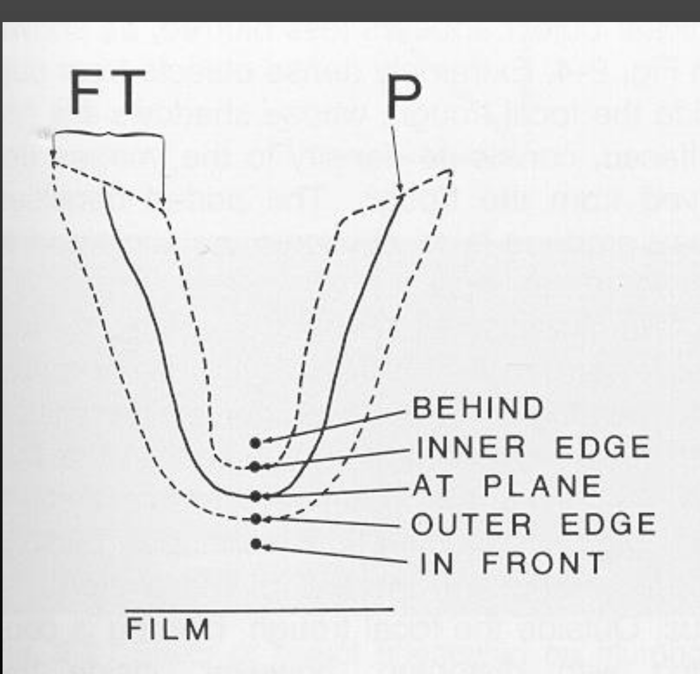
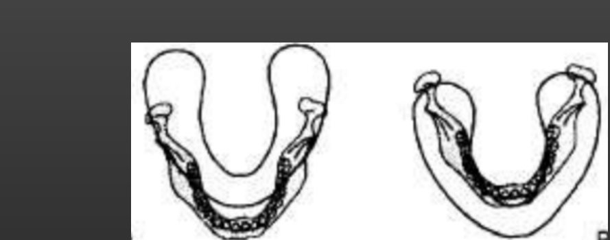
Focal Trough / Image Layer
FT
Fig. 1-10 Position of focal trough (FT) to the jaw for Panorex (left), Orthopantomograph (middle), and Panelipse (right) (based on the work of Lund and Manson-Hing, 1975a).
Note the posterior teeth are still within the focal trough
-
The focal trough in the anterior region is very thin, which often makes anterior teeth appear less accurate or distinct on an OPG.
-
Structures outside the focal trough, such as certain areas of the maxillary sinus, may be missed or poorly visualized.
-
FT
-
P
-
BEHIND
-
INNER EDGE
-
AT PLANE
-
OUTER EDGE
-
IN FRONT
-
FILM
 |  |  |
 |  |  |
 |  | 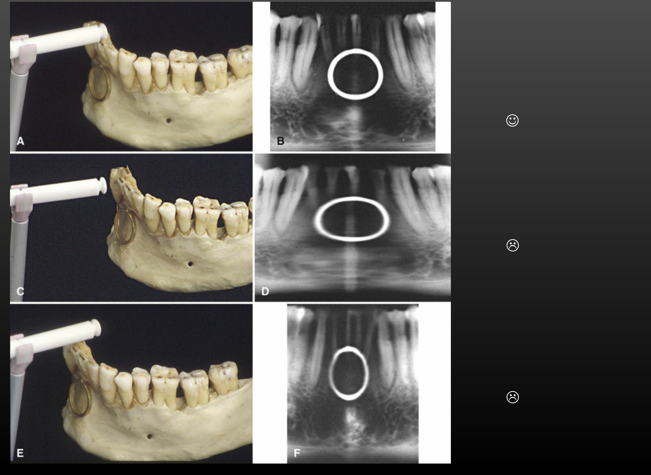 |
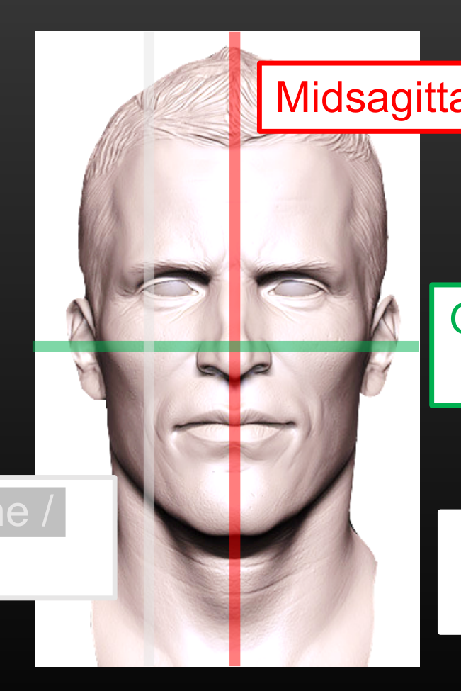
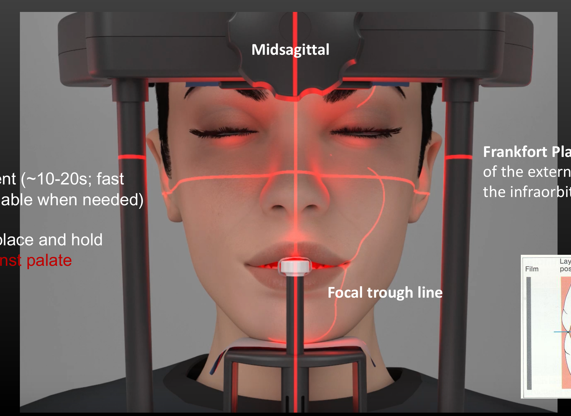
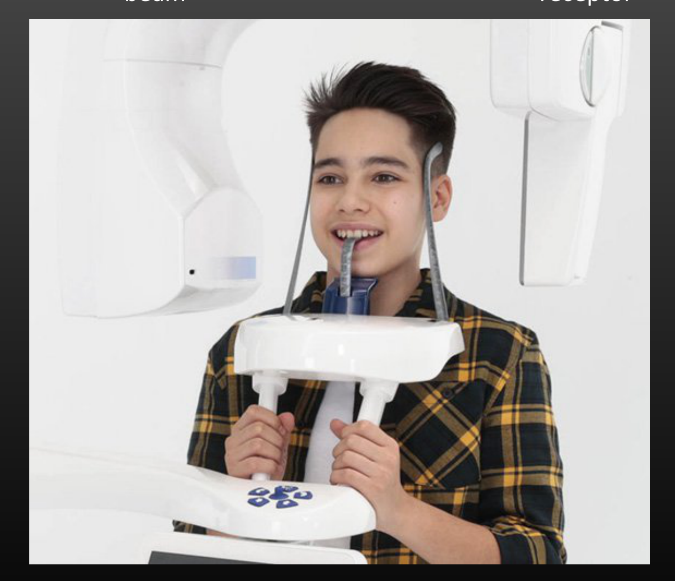
Patient Positioning Techniques11121314
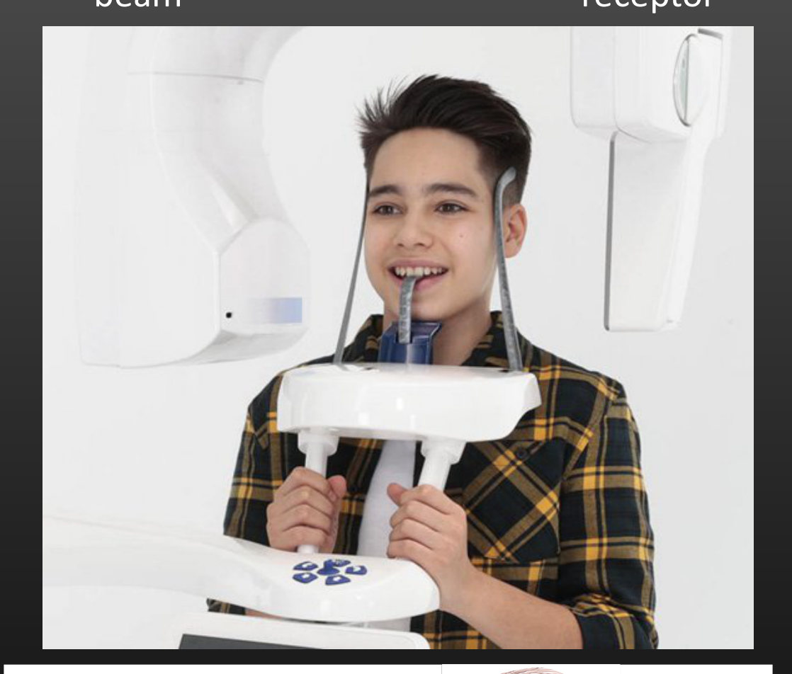
-
Midsagittal plane: centered
-
Occlusal/Frankfort plane: parallel to floor
-
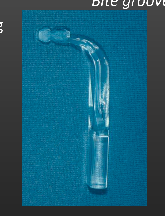
Focal trough line / canine line
-
Neck straight to avoid excessive overlap cervical spine
-
Midsagittal
-
No jewelry
-
No movement (~10-20s; fast modes available when needed)
-
Close lips, place and hold tongue against palate
-
Frankfort Plane: superior border of the external auditory meatus to the infraorbital rim
-
Focal trough line
 |  |  |
 |  |  |
 |  |  |
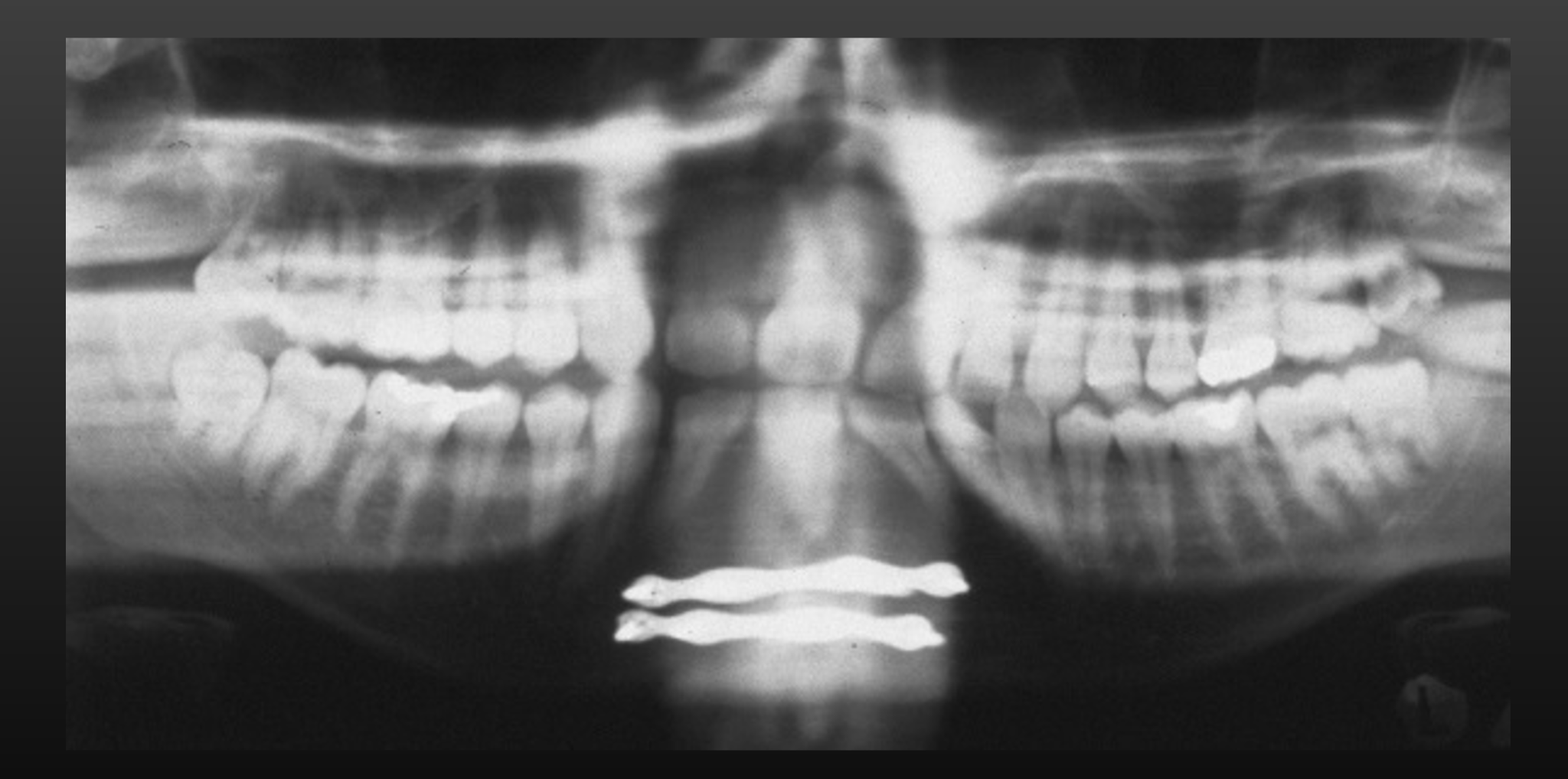
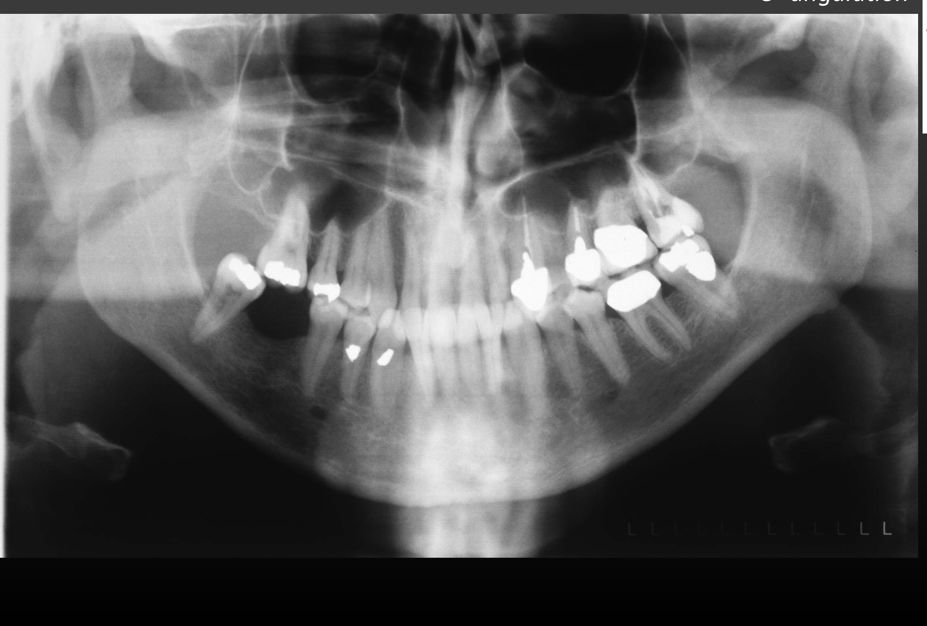
Positioning Errors and Image Distortion15161718
Positioning Errors
-
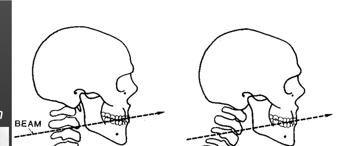
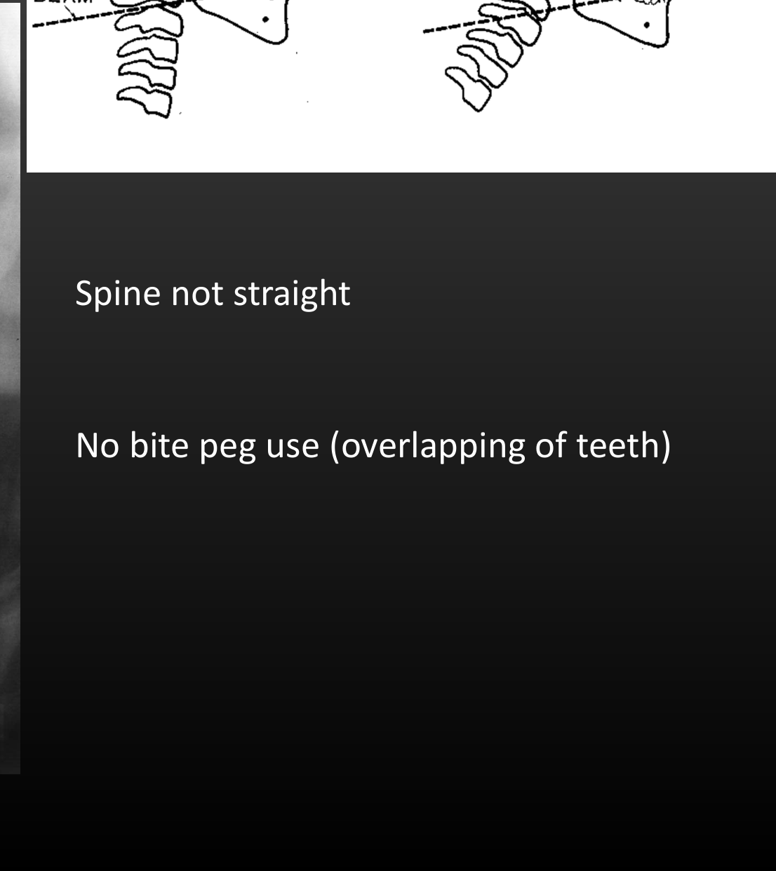
BEAM
-
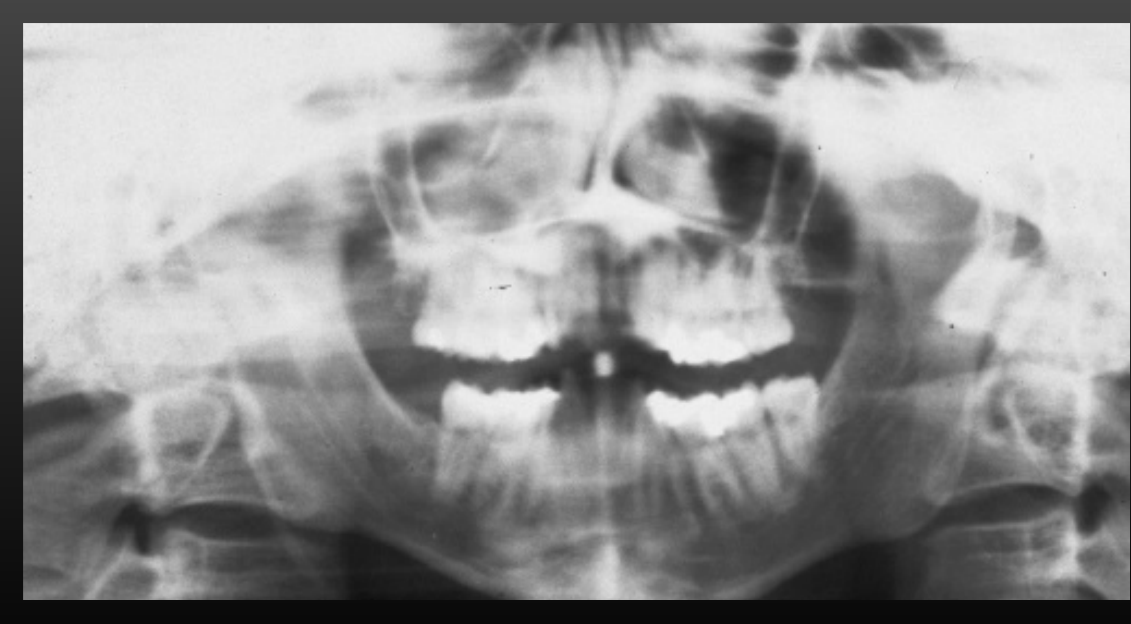
Spine not straight
-
No bite peg use (overlapping of teeth)
-
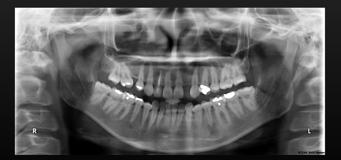
Artifacts are unavoidable in OPGs, but some are specifically related to patient positioning.
-
Due to the thin focal trough, anterior teeth are often not accurately represented.
-
Normal anatomical concavities, such as the lateral fossa or genial regions, can appear as radiolucencies (e.g., in the mandibular anterior region) and should not be mistaken for pathology.
 |  |  |
 |  |
Vertical and Horizontal Alignment Errors
Head tilting to the right19
- Incorrect midsagittal
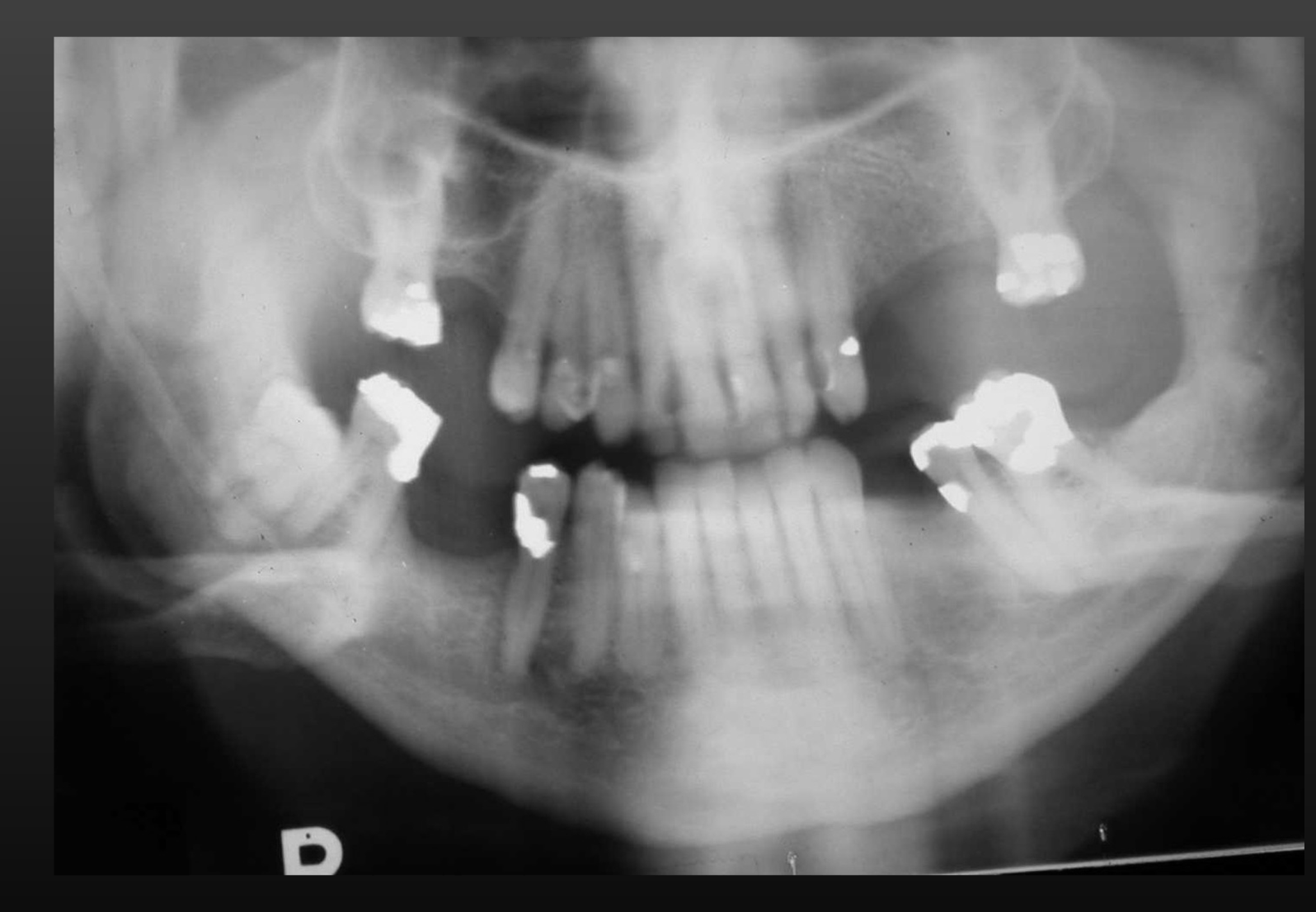
Chin down
- Incorrect Frankfort plane
- “Exaggerated smile”
- Superiorly positioned hyoid bone
- Condyles not visible (too high)
Neck extension
- Too much spine in the middle
The X-ray image of a dental scan.
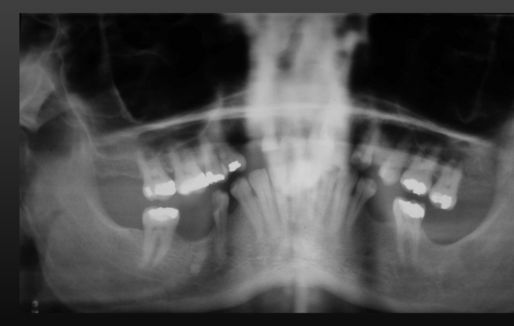
Chin up20
-
Incorrect Frankfort plane
-
“Reverse smile”
-
Condyles not visible
-
Too much spine in the middle
Tongue not touching the palate
- Palatoglossal airspace over the maxillary roots
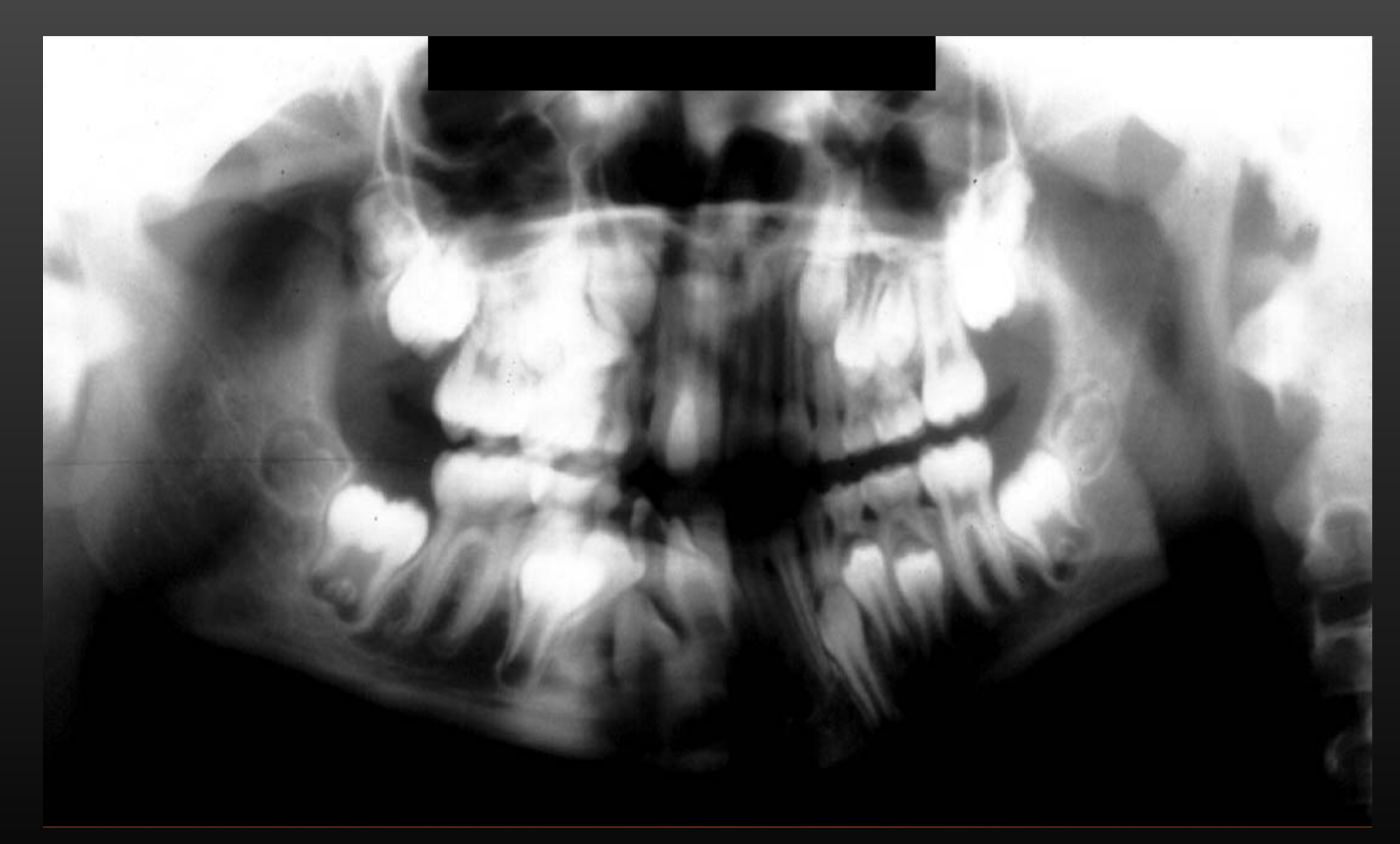
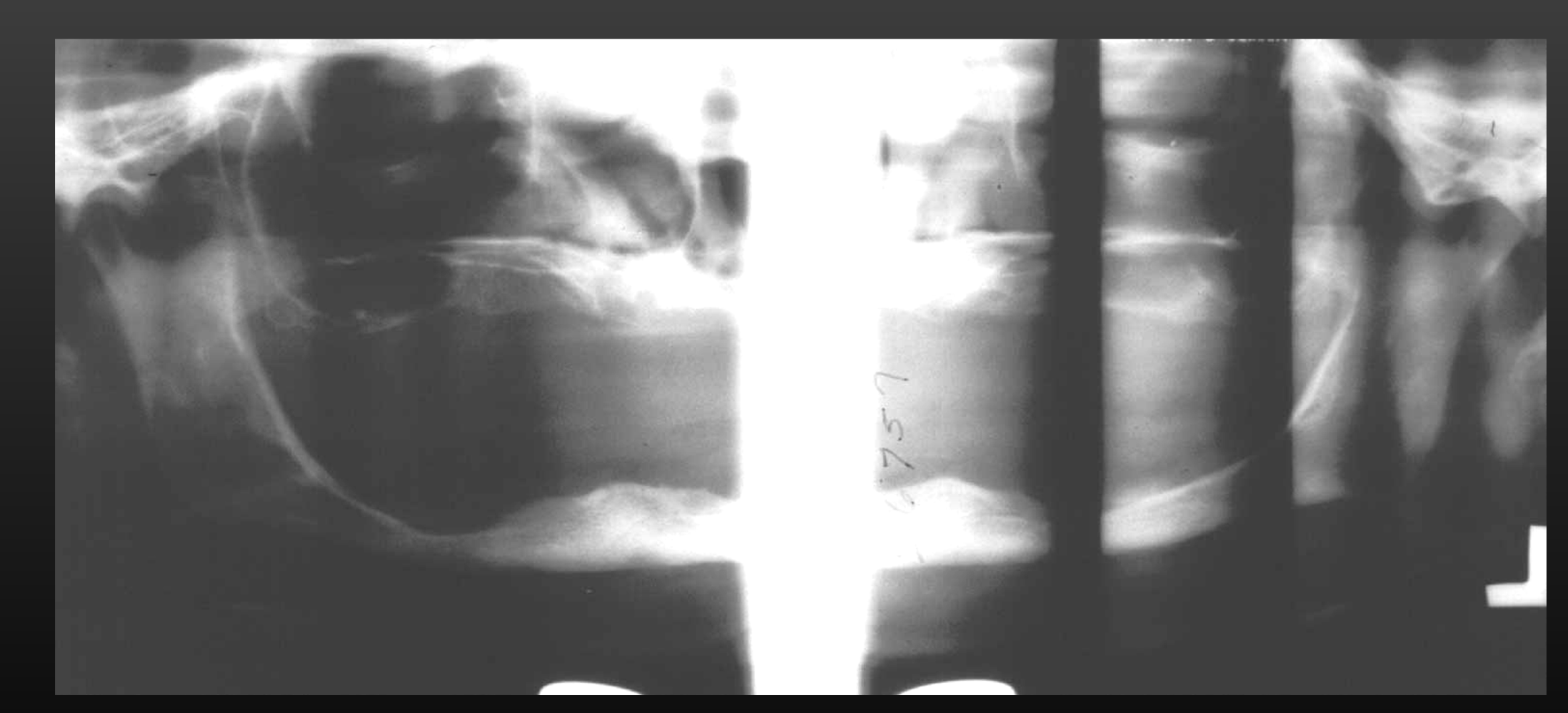
Rotation and Magnification Errors21222324
 |  |  |
 |  |
Rotated to the right (incorrect midsagittal)25
- Right-sided posterior teeth are behind the focal trough → horizontal magnification
- Asymmetry of the hemimandibles
- Opaque appearance of the left maxillary sinus
Rotated to R
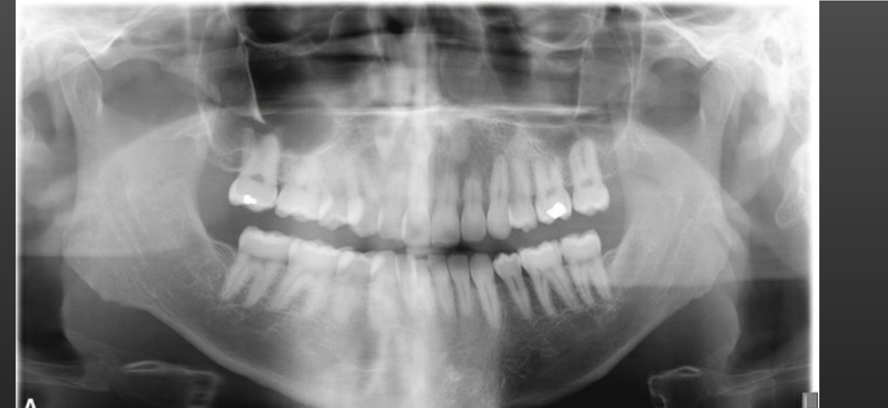 | 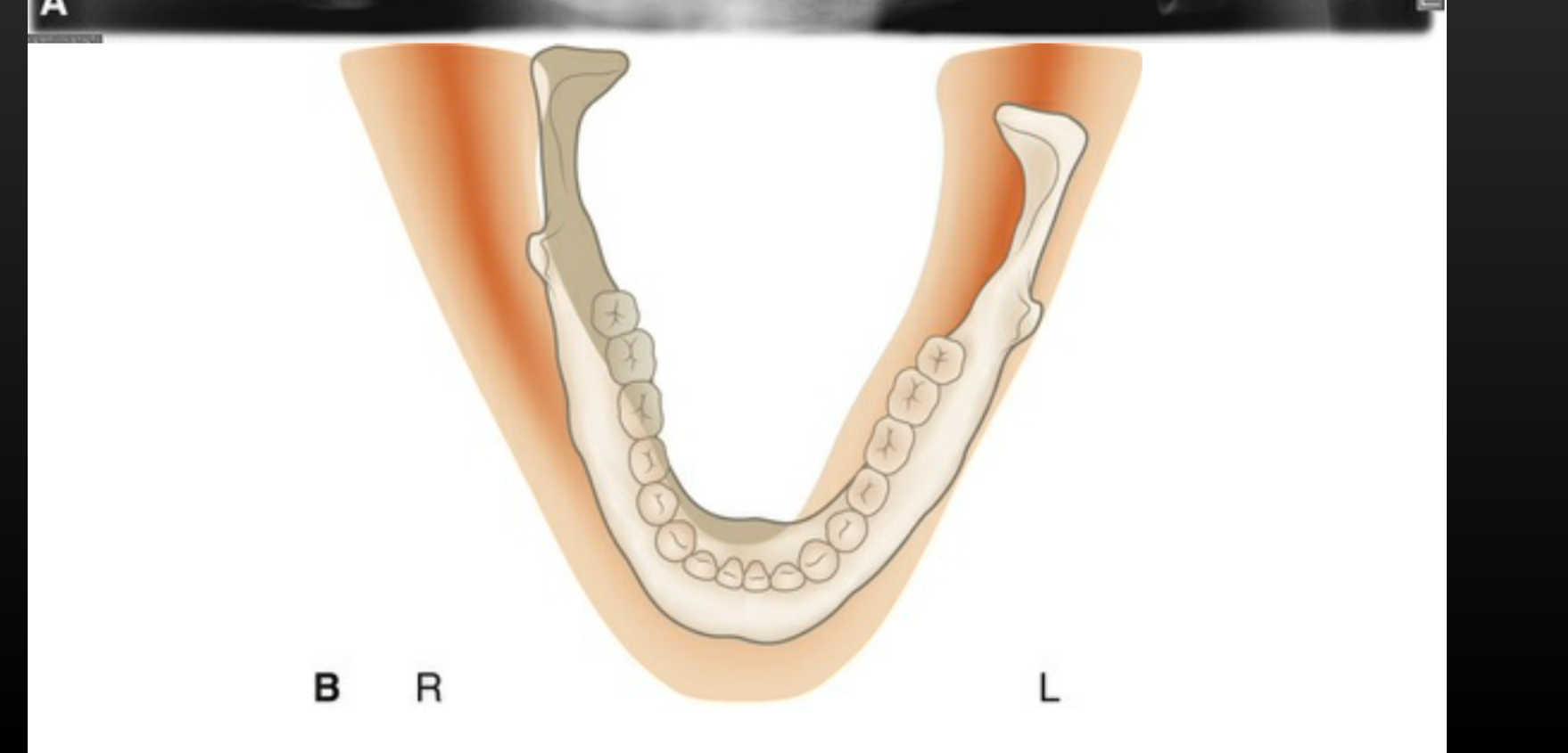 |
Image Formation and Artefacts
Real Images, Ghost Images & Double Images26
Real, Ghost, and Double Images2728
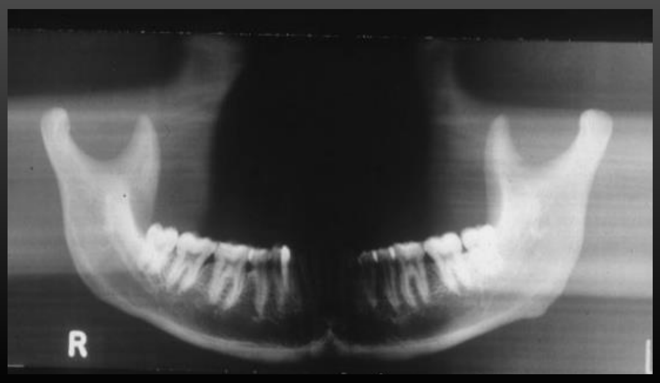 |  |
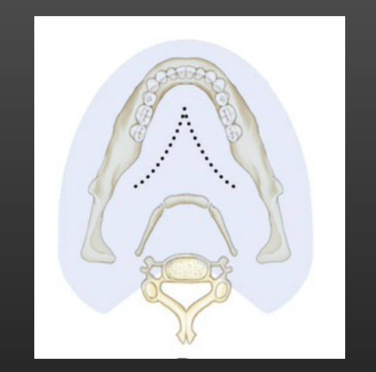
Real Image on OPG29
- Object is between centre of rotation and receptor
- Sharper if closer to focal trough
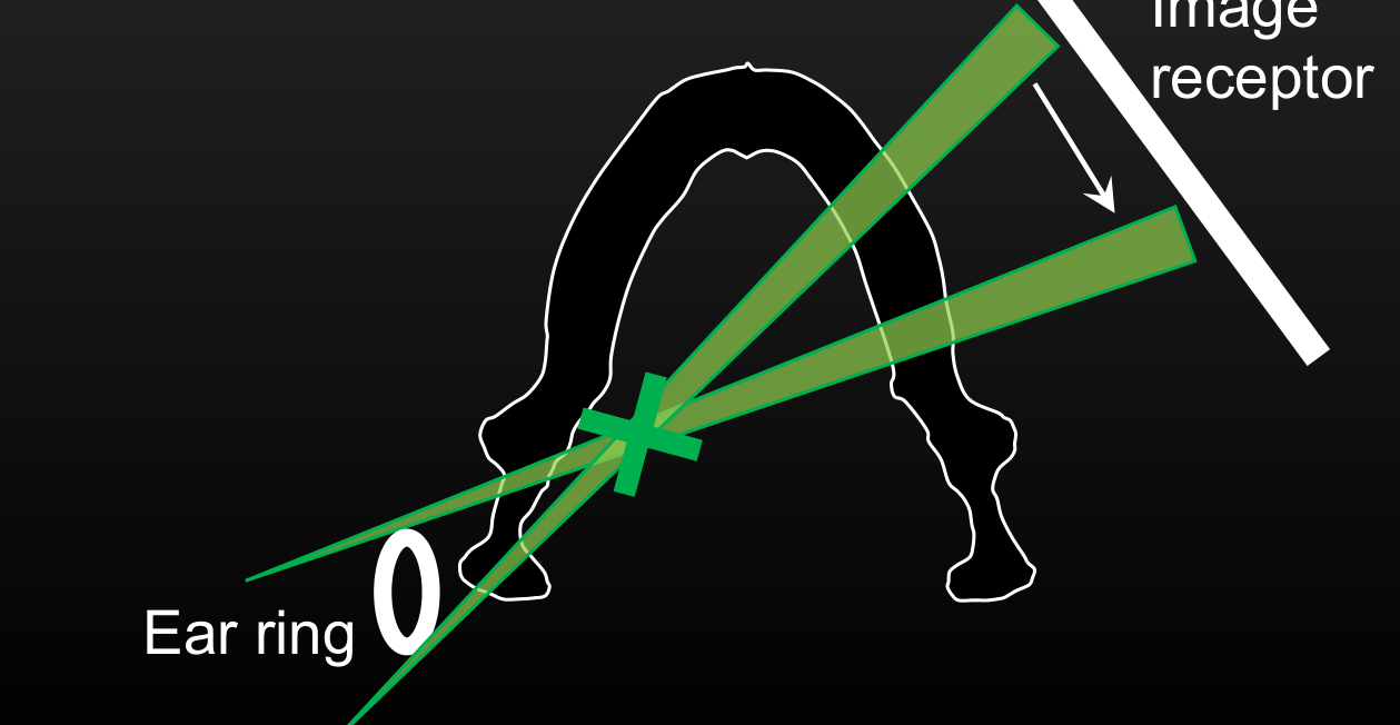
Ear ring 0 X ray tube L
 | 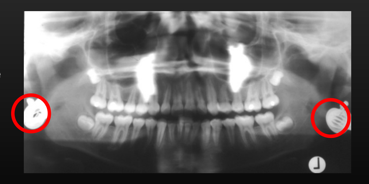 |
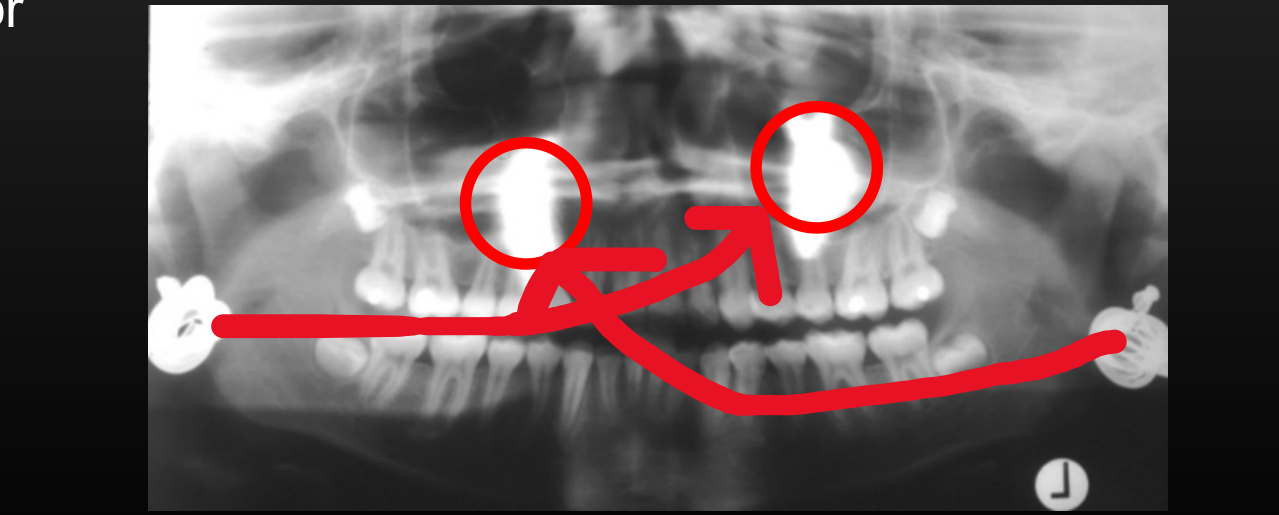
Ghost Image on OPG30
- Object between x-ray source and centre of rotation
- Usually outside of focal trough: appears blurred and magnified
- Appears on opposite side of image (L↔R) and higher on the image (due to upward beam) than their anatomical location
- Mandibular ramus, hyoid bone, cervical spine, earrings, etc.
 |  |
 |
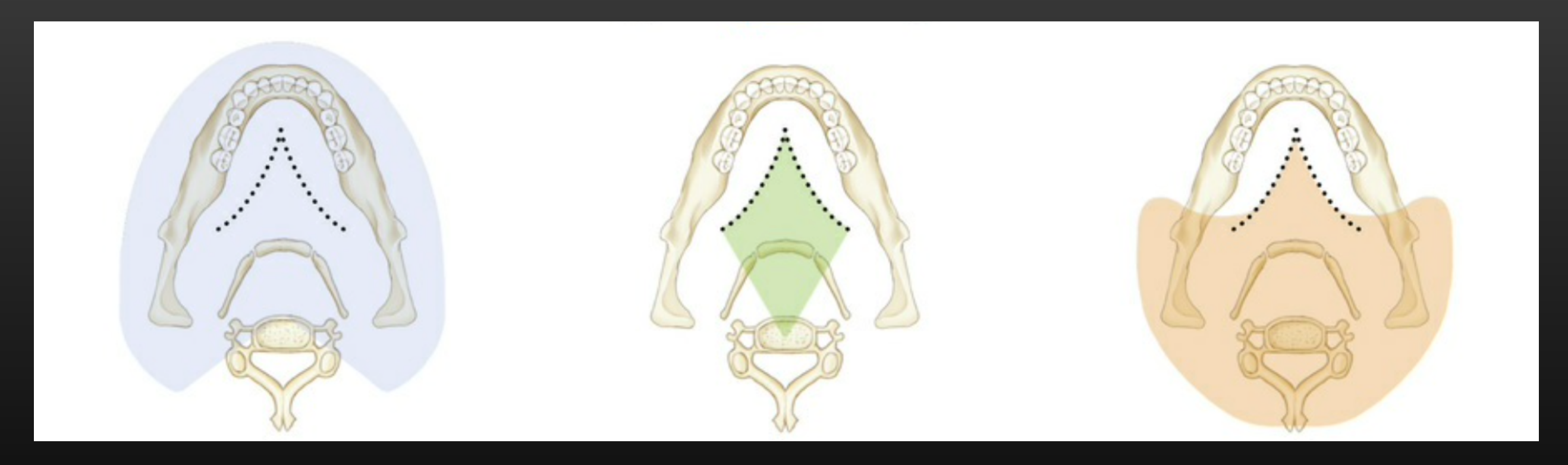
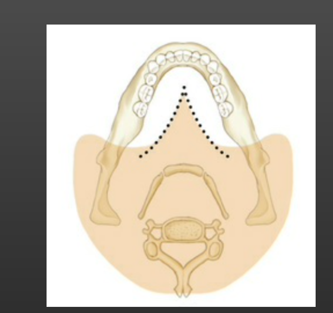
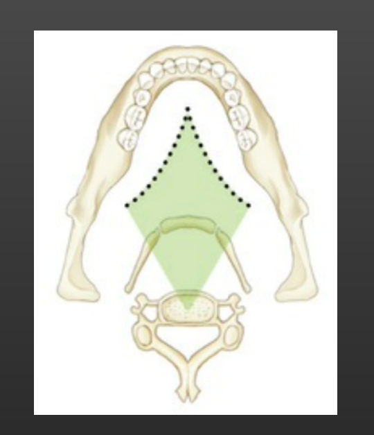
Double Image on OPG31
- Object is posterior to centre of rotation (the red diamond area) and intercepted by beam twice
- Structures in the centre eg. Hyoid bone, epiglottis, cervical spine, palate
- Double images are mirror images, appearing on the same location but opposite sides
Starting angle of panoramic exposure End angle of panoramic exposure Trajectory of center of rotation
 |  |
Common Radiographic Artefacts32
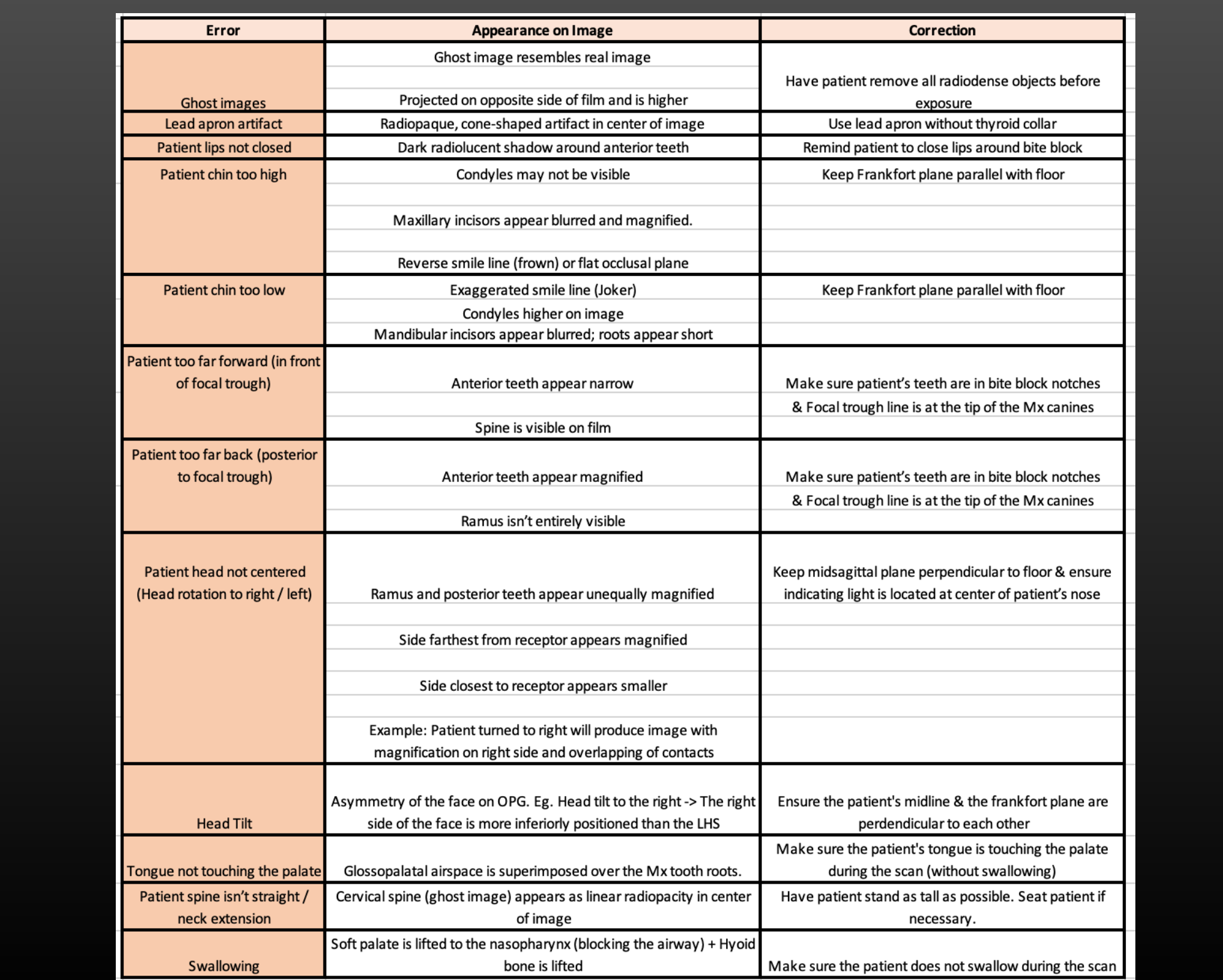
OPG artefacts33
- Incorrect patient positioning
- Chin down
- Chin up
- Head tilting
- Head rotation
- Movement
- Horizontal (following the beam or opposite to the beam direction)
- Vertical
- Swallowing
- Soft tissue position
- Tongue to the palate
- Lips closed
- Focal trough position
- Head in front of the focal trough
- Head behind the focal trough
- Neck extension
- Collision with shoulder
- Ghost images
- Foreign materials eg. Earrings, necklace, denture left in situ, etc.
| Error | Appearance on Image | Correction |
|---|---|---|
| Ghost images | Ghost image resembles real image | Have patient remove all radiodense objects before exposure |
| Projected on opposite side of film and is higher | ||
| Lead apron artifact | Radiopaque, cone-shaped artifact in center of image | Use lead apron without thyroid collar |
| Patient lips not closed | Dark radiolucent shadow around anterior teeth | Remind patient to close lips around bite block |
| Patient chin too high | Condyles may not be visible | Keep Frankfort plane parallel with floor |
| Maxillary incisors appear blurred and magnified. | ||
| Reverse smile line (frown) or flat occlusal plane | ||
| Patient chin too low | Exaggerated smile line (Joker) | Keep Frankfort plane parallel with floor |
| Condyles higher on image | ||
| Mandibular incisors appear blurred; roots appear short | ||
| Patient too far forward (in front of focal trough) | Anterior teeth appear narrow | Make sure patient’s teeth are in bite block notches & Focal trough line is at the tip of the Mx canines |
| Spine is visible on film | ||
| Patient too far back (posterior to focal trough) | Anterior teeth appear magnified | Make sure patient’s teeth are in bite block notches & Focal trough line is at the tip of the Mx canines |
| Ramus isn’t entirely visible | ||
| Patient head not centered (Head rotation to right / left) | Ramus and posterior teeth appear unequally magnified | Keep midsagittal plane perpendicular to floor & ensure indicating light is located at center of patient’s nose |
| Side farthest from receptor appears magnified | ||
| Side closest to receptor appears smaller | ||
| Example: Patient turned to right will produce image with magnification on right side and overlapping of contacts | ||
| Head Tilt | Asymmetry of the face on OPG. Eg. Head tilt to the right -> The right side of the face is more inferiorly positioned than the LHS | Ensure the patient’s midline & the frankfort plane are perpendicular to each other |
| Tongue not touching the palate | Glossopalatal airspace is superimposed over the Mx tooth roots. | Make sure the patient’s tongue is touching the palate during the scan (without swallowing) |
| Patient spine isn’t straight / neck extension | Cervical spine (ghost image) appears as linear radiopacity in center of image | Have patient stand as tall as possible. Seat patient if necessary. |
| Swallowing | Soft palate is lifted to the nasopharynx (blocking the airflow) + Hyoid bone is lifted | Make sure the patient does not swallow during the scan |
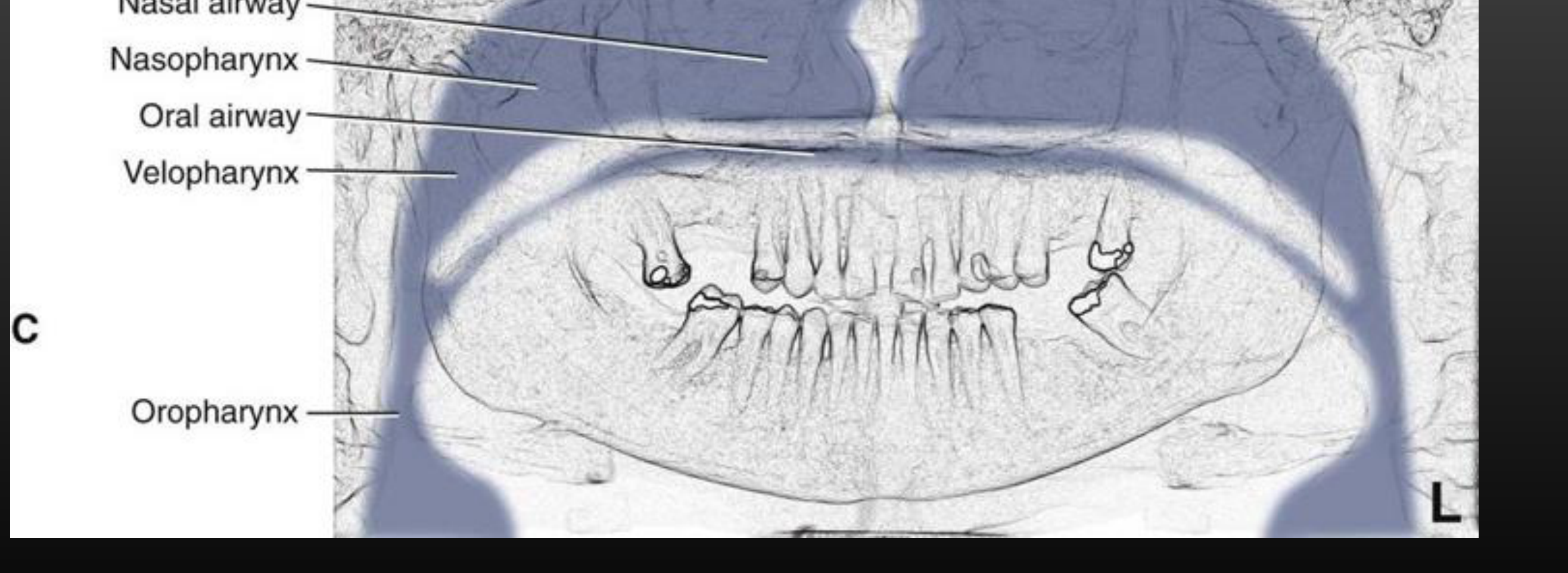
- Airway Interference: The nasopharynx and oropharynx are visible at the back of the throat. Narrowing or prominence of the posterior pharyngeal wall should be noted.
- Superimposition: Teeth and roots are often superimposed over structures like the maxillary sinus or adjacent teeth, which can complicate the assessment of resorption or perforation.
Anatomical Structures in Panoramic Imaging343536373839
OPG Anatomy
-
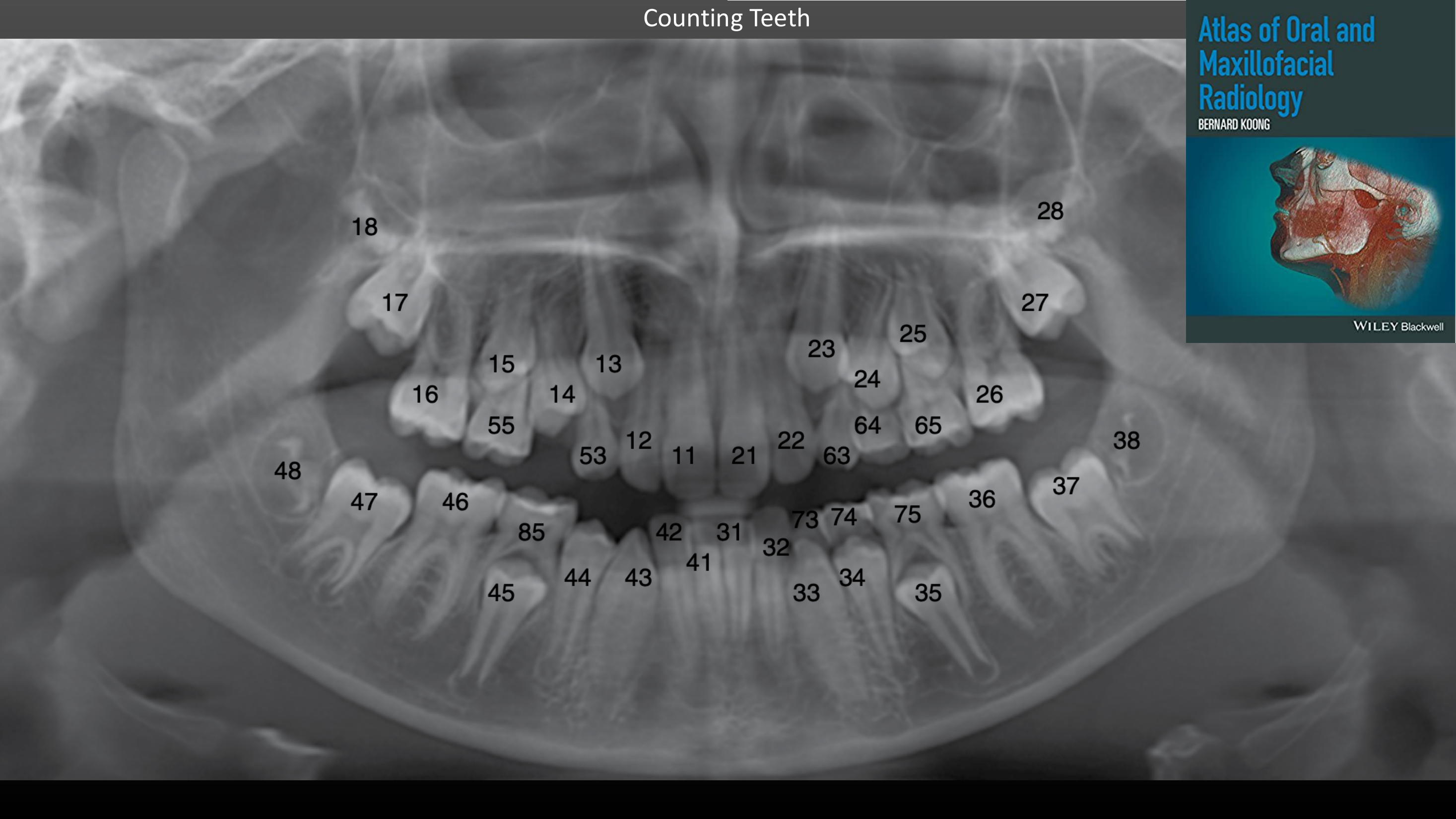
Teeth (count teeth first)
-
Hard palate & Soft palate
-
Maxilla
- Incisive canal
- Intermaxillary suture
- Maxillary sinuses
- Draw Floor, Anterior and Posterior walls
- Innominate line (zygomatic process)
-
Mandible
- Angle, ramus, body, coronoid process, condylar neck, condylar head, pterygoid fovea, sigmoid notch
- External oblique ridge
- Submandibular fossa
- Mandibular canal & Mental foramen
-
Zygomatic arch
- Zygomatico-zygomatic suture
- Zygomatic process of temporal bone
-
Articular eminence
-
Pterygoid plates
-
Pterygomaxillary fissure
-
Orbital rims
-
Infraorbital canal & foramen
-
Nose
- Nasal cavity, septum, turbinate (conchae)
- Soft tissue
-
Anterior na
-
Reports should be succinct, ideally no longer than one page.
-
Use a checklist to ensure all areas are reviewed even if not explicitly written in the final report.sal spine
-
Hyoid bone
-
Epiglottis
-
Cervical spine
- C1, C2, C3, C4
- Atlanto-axial joint space
-
Styloid process
-
Mastoid process
-
Ears
- External auditory meati
- Soft tissue
-
Tongue (dorsal border)
-
Tonsillar tissues (if visible)
-
Facial soft tissue creases – e.g. naso-labial folds (if visible)
-
Posterior pharyngeal wall
-
Airspaces
- Palatoglossal airspace (when tongue is not up)
- Nasopharynx and oropharynx
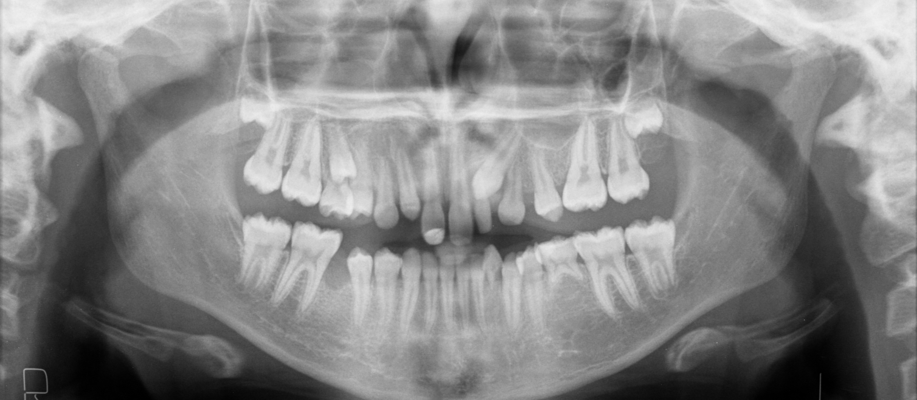
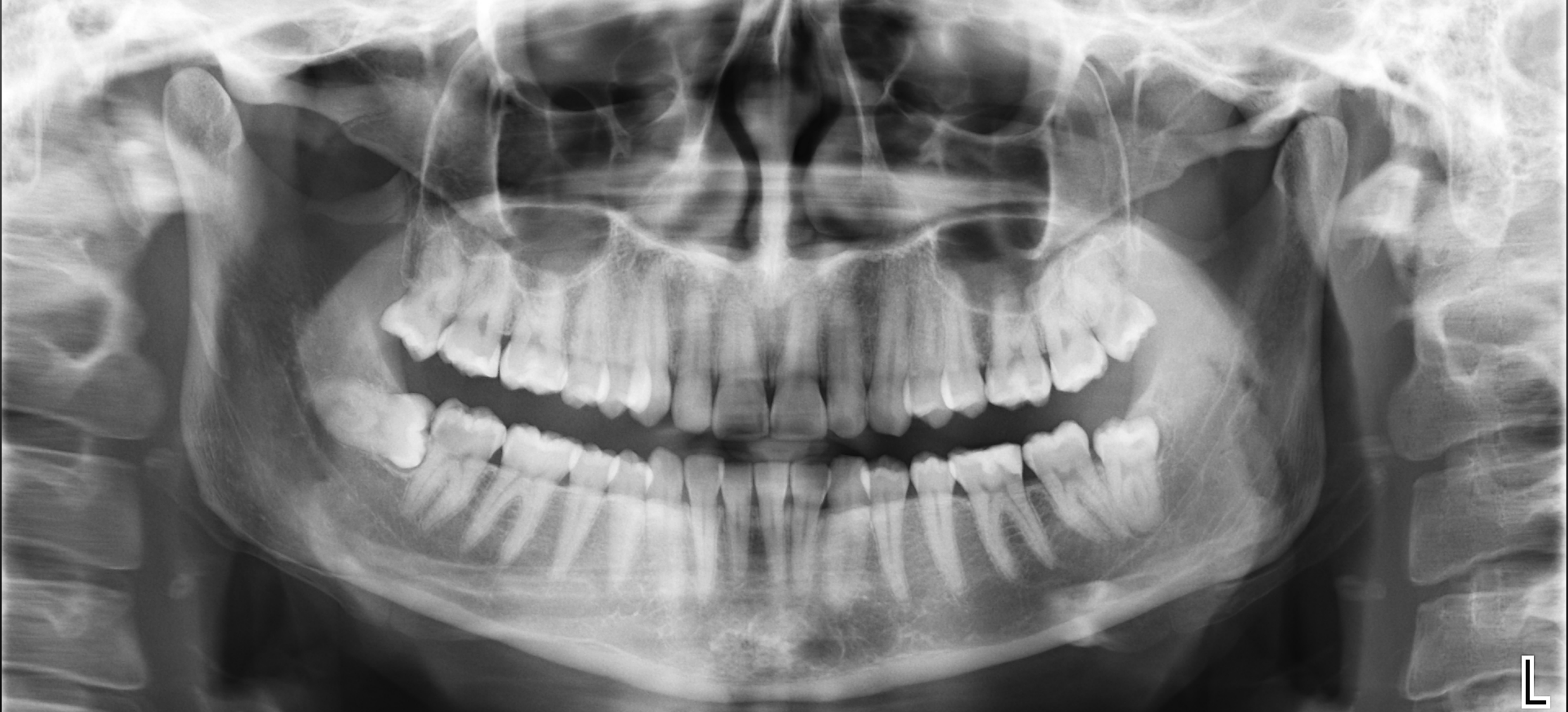
Practice OPG #1
Find retained deciduous teeth
 |  |
 |  |
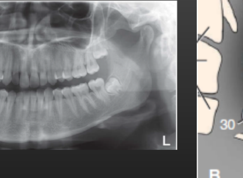
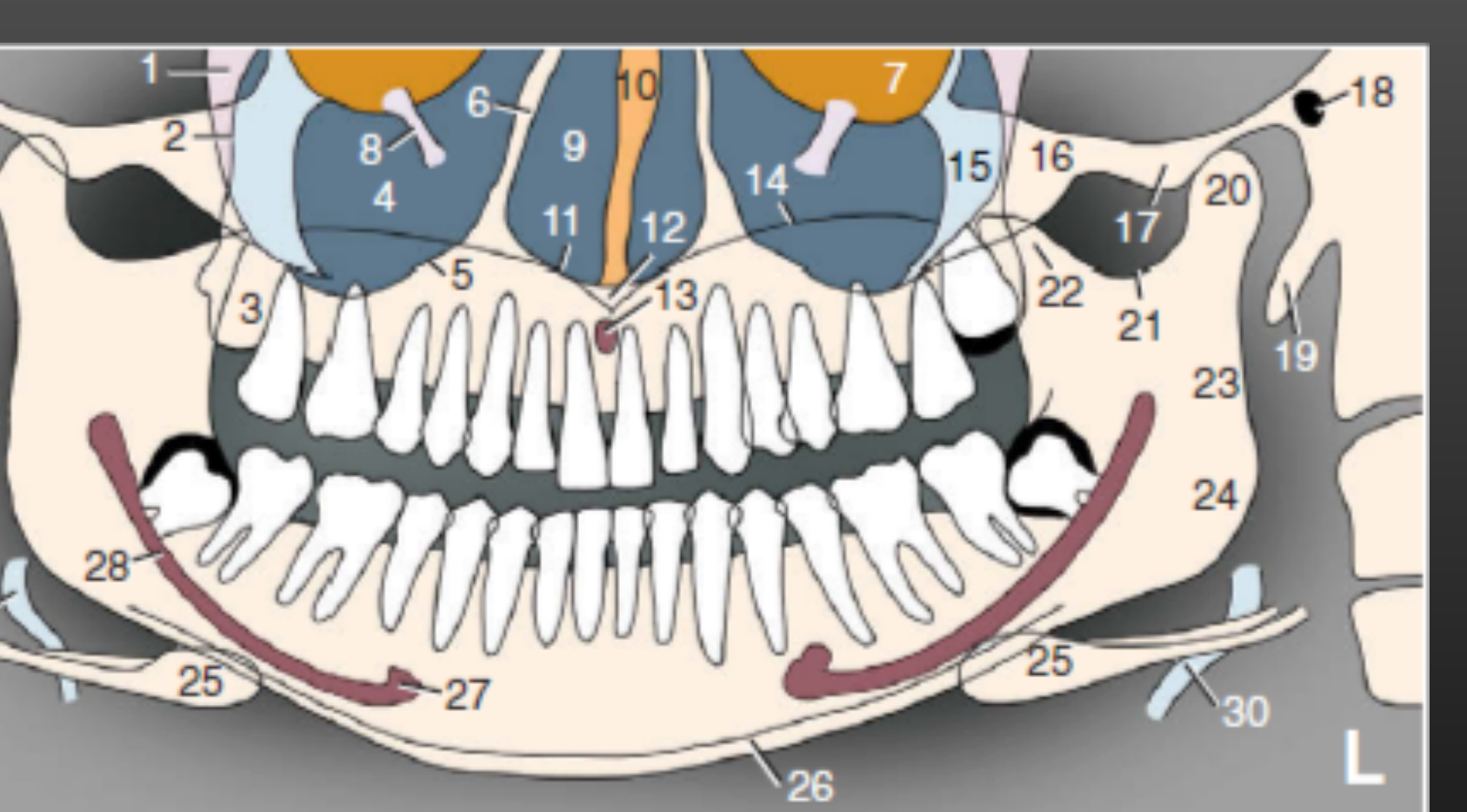
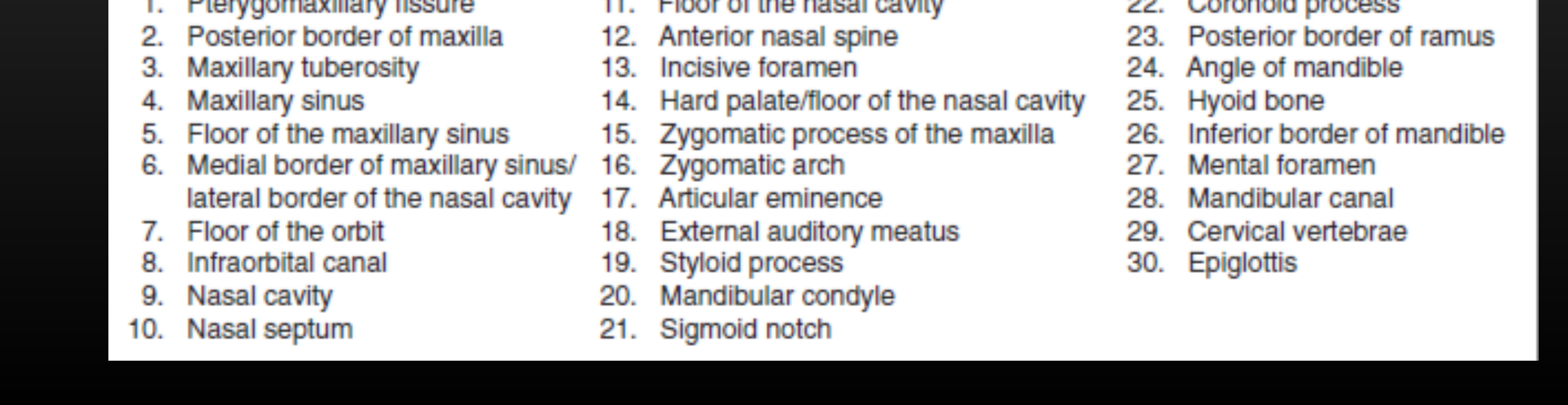
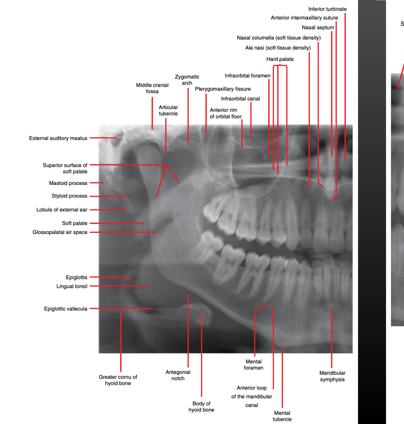
Maxillary and Mandibular Anatomy404142434445
Note the double image of palate, hyoid & spine
- Pterygomaxillary fissure
- Posterior border of maxilla
- Maxillary tuberosity
- Maxillary sinus
- Floor of the maxillary sinus
- Maxillary Sinuses: OPGs show the medial wall, floor, and posterior wall. Walls should be thin and cortical.
- Medial border of maxillary sinus/ lateral border of the nasal cavity
- Floor of the orbit
- Infraorbital canal
- Nasal cavity
- Nasal septum
- Floor of the nasal cavity
- Anterior nasal spine
- Incisive foramen
- Hard palate/floor of the nasal cavity
- Trabecular Pattern: Healthy bone should show a porous, “honeycomb-like” pattern. Alterations (e.g., ground-glass appearance or empty spaces) may indicate pathology.
- Zygomatic process of the maxilla
- Zygomatic arch
- Articular eminence
- External auditory meatus
- Styloid process
- Mandibular condyle
TM Joints
OPGs are suitable only for identifying gross morphological changes, such as fractures or significant asymmetry.
- Sigmoid notch
- Coronoid process
- Posterior border of ramus
- Angle of mandible
- Hyoid bone
- Inferior border of mandible
- Mental foramen
- Mandibular canal
- The relationship between the canal and the roots of impacted third molars is a key observation.
- Cervical vertebrae
- Epiglottis
- Soft Tissues: While OPGs are a hard tissue modality, soft tissue densities, swellings, or tonsilloliths (tonsil stones) can be visualized.
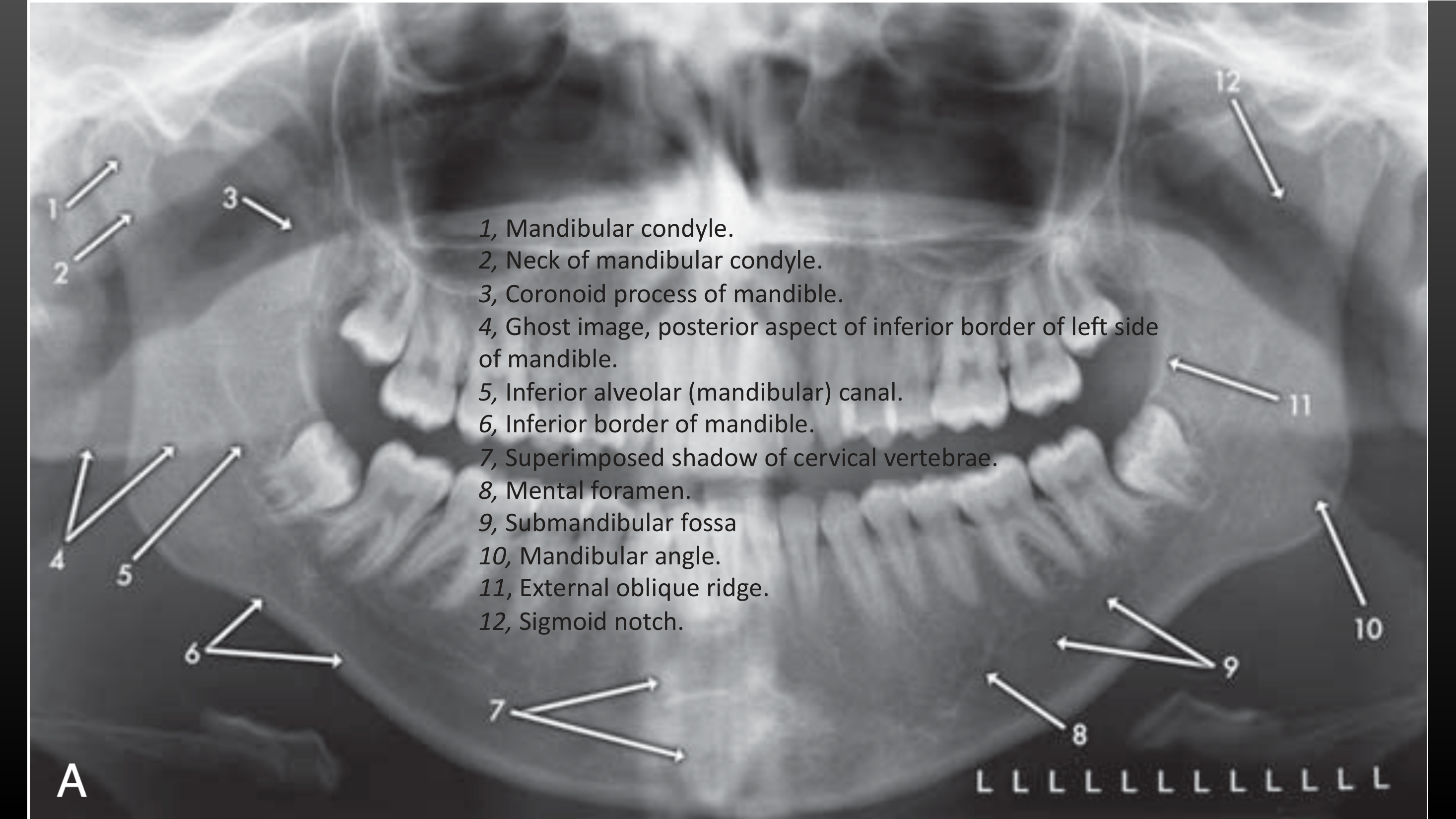
Dental X-ray showing mandible anatomy.
-
Mandibular condyle.
-
Neck of mandibular condyle.
-
Coronoid process of mandible.
-
Ghost image, posterior aspect of inferior border of left side of mandible.
-
Inferior alveolar (mandibular) canal.
-
Inferior border of mandible.
-
Superimposed shadow of cervical vertebrae.
-
Mental foramen.
-
Submandibular fossa
-
Mandibular angle.
-
External oblique ridge.
-
Sigmoid notch.
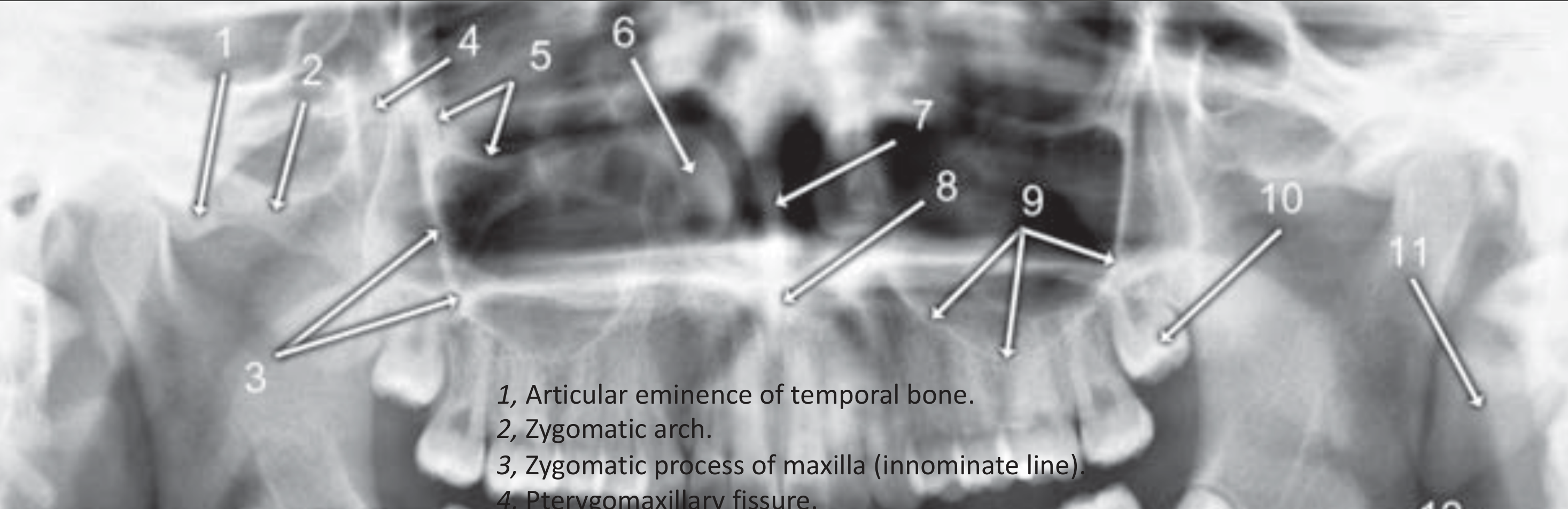
-
Articular eminence of temporal bone.
-
Zygomatic arch.
-
Zygomatic process of maxilla (innominate line).
-
Pterygomaxillary fissure.
-
Floor of orbit.
-
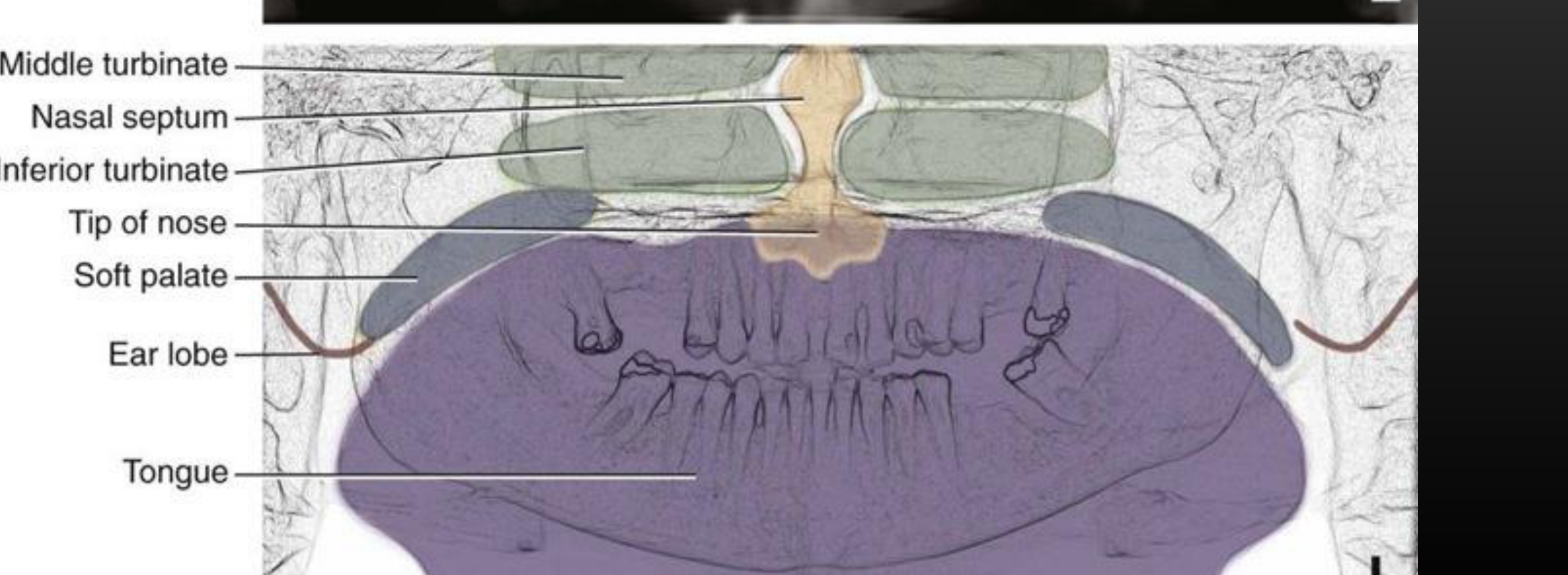
inferior turbinate / concha.
-
Nasal septum.
-
Anterior nasal spine.
-
Floor of maxillary sinus.
-
Maxillary left third molar (developing).
-
Ear lobe.
-
Cervical vertebral body.
 |  |  |
 |  |  |
 |  |
Clinical Indications and Limitations46
OPGs are NOT accurate for caries assessment
Clinical Indications:
- General dental screening:
- Impacted third molars
- Periodontal screening (periodontal bone loss)
- Mixed dentition & Eruption pattern of permanent teeth
- Orthodontics:
- Crowding, impacted canines, etc.
- Dental anomalies
- Jaw Pathology:
- Inflammatory lesions, odontogenic tumours & cysts, etc.
- Trauma (esp. mandibular fracture)
- TM Joints (not accurate)
Further Reading and Resources
Systematic Interpretation Approach
- Check for technical/positional errors and artifacts.
- Address the primary clinical concern (e.g., site of pain).
- Dentoalveolar assessment (count teeth, identify anomalies, assess bone loss).
- Maxilla and Mandible (check trabecular patterns and cortical borders).
- Maxillary Sinuses and TMJs.
- Soft tissues and other areas (airways, spine).
Audio Appendix
Additional Audio Content
The following sections from the lecture audio did not correspond to any heading in the main document.
Indications
- Heavily Compromised Dentition: Useful for patients with advanced caries or multiple broken teeth.
- Periodontal Screening: The most common indication; allows for the assessment of generalized horizontal bone loss across all four quadrants.
- Impacted Third Molars: Used to determine angulation and the relationship between roots and the mandibular canal or maxillary sinus.
- Mixed Dentition Status: Useful for checking dental age versus physiological age and identifying anomalies in pediatric patients.
- Orthodontic Assessment: Routine baseline for orthodontic planning.
- Dental Anomalies: Identifying supernumerary teeth, missing teeth (hypodontia/oligodontia), or malformed teeth.
- Jaw Pathology: Baseline imaging for intra-bony lesions, cysts, or tumors to assess if they are expansile or erosive.
- Trauma: Baseline for condylar fractures, though CT is the gold standard for trauma.
Case Study: Case Number Two (Periodontal Disease)
- Findings: Generalized minor to moderate horizontal bone loss.
- Perio-Endo Lesion: A significant defect at the 27 site extending beyond the root apices, termed a “perio-endo bony defect.”
- Furcation: Lucency at the 36 furcation suggests a furcation bone defect or a root fracture.
- Implants: Maxillary implants (17, 16, 15) show no bone loss. The mandibular implant at 46 shows bone loss extending to the third thread, suggesting peri-implantitis.
Case Study: Case Number Three (Impacted Third Molars and Anomalies)
- Supernumerary Tooth: An extra tooth is noted in quadrant 4, positioned distal-superior to the 48.
- Winter’s Classification of Impactions:
- 18, 28, 38: Disto-angular impactions.
- 48: Mesio-angular impaction.
- Supernumerary: Horizontally impacted.
- Observations: Roots of 18 and 28 approximate the maxillary sinus floor. Roots of 38 and 48 likely contact the mandibular canal.
Limitations
- Spatial Resolution: Not ideal for early caries detection.
- 2D Representation: Cannot provide the exact 3D location of teeth or the precise relationship of roots to nerves/sinuses (requires CT/CBCT for detail).
- Diagnostic Responsibility: Dentists who self-report OPGs are legally responsible for all radiographic findings.
Case Study: Case Number One (Heavily Compromised Dentition)
- Findings: Broken teeth with retained root fragments at sites 16, 14, 27, 36, and 46. Radiolucencies around these fragments suggest inflammatory lesions.
- Caries: Gross lucencies noted on 17 and 37 crowns.
- Missing Teeth: 18, 15, 28, and 47.
- Impacted Teeth: 38 and 48 are impacted with roots approximating the mandibular canal.
- Bone Loss: Generalized minor to moderate horizontal bone loss.
- Sinus: Minor mucosal thickening noted at the floor of the right and left maxillary sinuses, likely reactive to dental inflammation.
Footnotes
-
Original PDF page 1: L8 Panoramic Radiography, p.1 ↩
-
Original PDF page 2: L8 Panoramic Radiography, p.2 ↩
-
Original PDF page 3: L8 Panoramic Radiography, p.3 ↩
-
Original PDF page 4: L8 Panoramic Radiography, p.4 ↩
-
Original PDF page 5: L8 Panoramic Radiography, p.5 ↩
-
Original PDF page 6: L8 Panoramic Radiography, p.6 ↩
-
Original PDF page 7: L8 Panoramic Radiography, p.7 ↩
-
Original PDF page 8: L8 Panoramic Radiography, p.8 ↩
-
Original PDF page 9: L8 Panoramic Radiography, p.9 ↩
-
Original PDF page 10: L8 Panoramic Radiography, p.10 ↩
-
Original PDF page 11: L8 Panoramic Radiography, p.11 ↩
-
Original PDF page 12: L8 Panoramic Radiography, p.12 ↩
-
Original PDF page 13: L8 Panoramic Radiography, p.13 ↩
-
Original PDF page 14: L8 Panoramic Radiography, p.14 ↩
-
Original PDF page 15: L8 Panoramic Radiography, p.15 ↩
-
Original PDF page 16: L8 Panoramic Radiography, p.16 ↩
-
Original PDF page 17: L8 Panoramic Radiography, p.17 ↩
-
Original PDF page 18: L8 Panoramic Radiography, p.18 ↩
-
Original PDF page 19: L8 Panoramic Radiography, p.19 ↩
-
Original PDF page 20: L8 Panoramic Radiography, p.20 ↩
-
Original PDF page 22: L8 Panoramic Radiography, p.22 ↩
-
Original PDF page 23: L8 Panoramic Radiography, p.23 ↩
-
Original PDF page 24: L8 Panoramic Radiography, p.24 ↩
-
Original PDF page 25: L8 Panoramic Radiography, p.25 ↩
-
Original PDF page 21: L8 Panoramic Radiography, p.21 ↩
-
Original PDF page 26: L8 Panoramic Radiography, p.26 ↩
-
Original PDF page 29: L8 Panoramic Radiography, p.29 ↩
-
Original PDF page 31: L8 Panoramic Radiography, p.31 ↩
-
Original PDF page 27: L8 Panoramic Radiography, p.27 ↩
-
Original PDF page 28: L8 Panoramic Radiography, p.28 ↩
-
Original PDF page 30: L8 Panoramic Radiography, p.30 ↩
-
Original PDF page 33: L8 Panoramic Radiography, p.33 ↩
-
Original PDF page 32: L8 Panoramic Radiography, p.32 ↩
-
Original PDF page 34: L8 Panoramic Radiography, p.34 ↩
-
Original PDF page 35: L8 Panoramic Radiography, p.35 ↩
-
Original PDF page 36: L8 Panoramic Radiography, p.36 ↩
-
Original PDF page 37: L8 Panoramic Radiography, p.37 ↩
-
Original PDF page 38: L8 Panoramic Radiography, p.38 ↩
-
Original PDF page 39: L8 Panoramic Radiography, p.39 ↩
-
Original PDF page 40: L8 Panoramic Radiography, p.40 ↩
-
Original PDF page 41: L8 Panoramic Radiography, p.41 ↩
-
Original PDF page 42: L8 Panoramic Radiography, p.42 ↩
-
Original PDF page 43: L8 Panoramic Radiography, p.43 ↩
-
Original PDF page 44: L8 Panoramic Radiography, p.44 ↩
-
Original PDF page 45: L8 Panoramic Radiography, p.45 ↩
-
Original PDF page 46: L8 Panoramic Radiography, p.46 ↩