Cephalograms and Other 2D Extraoral Views1
Dr Dayea Oh OMF Radiologist
Learning Objectives2
- What are intensifying screens?
- Understanding the purpose of using intensifying screens in extraoral radiography
- Understanding differences between Cephalograms and Skull Views
- What are the clinical indications for:
- Lateral cephalogram (Lat Ceph)
- Frontal Views
- Submentovertex (SMV) Projection
- Water’s View
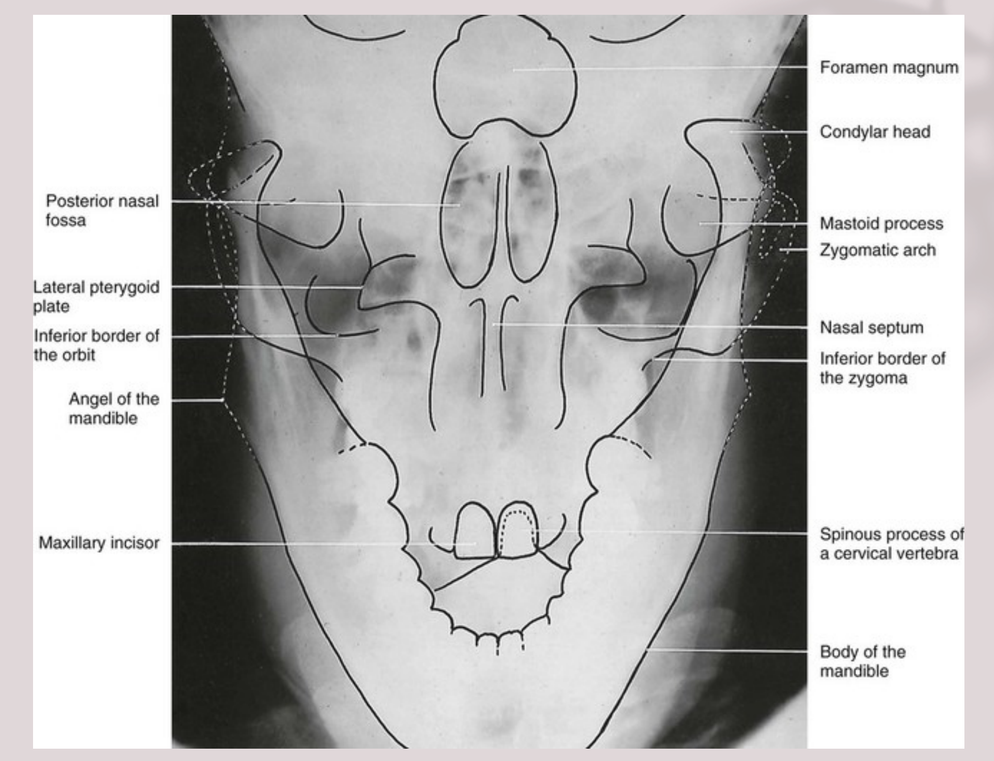
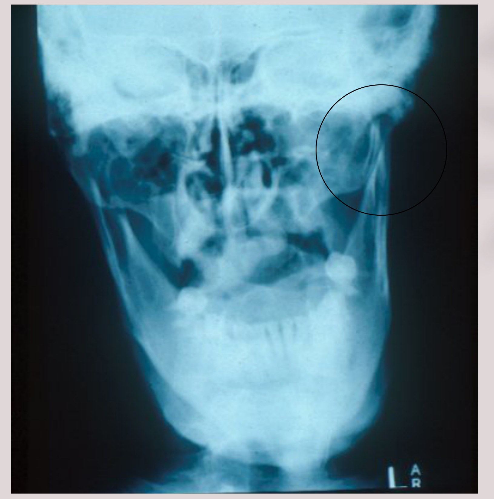
- Reverse Towne View
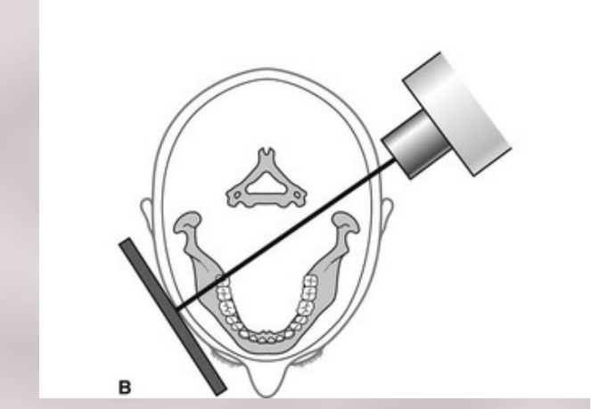
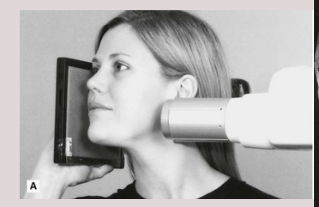
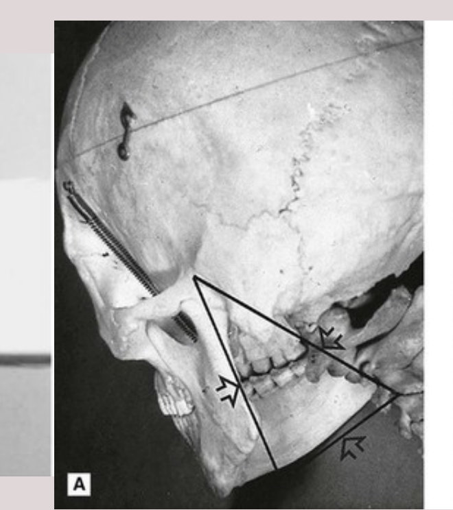
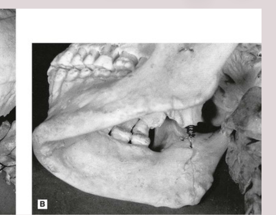
- Lateral Oblique (or Oblique Lateral) Radiograph
Introduction to Extraoral Radiography
Extraoral radiography involves placing the X-ray source and image receptor outside the mouth.
General Indications3
- Patient is unable to open mouth
- Severe gag reflex
- Trauma
- Impacted third molars
- Extensive jaw pathology
- TM joint assessment
- Orthodontic & orthognathic treatment planning
Technical Background and Equipment
X-Ray Cassette Components4
The cassette consists of the following layers (from front to back):
- Cassette front
- Front padding
- Intensifying screen
- Support layer
- Phosphor layer
- Emulsion layer (double-coated film)
- Support layer (film base)
- Emulsion layer
- Intensifying screen
- Phosphor layer
- Support layer
- Lead foil
- Back padding
- Cassette back
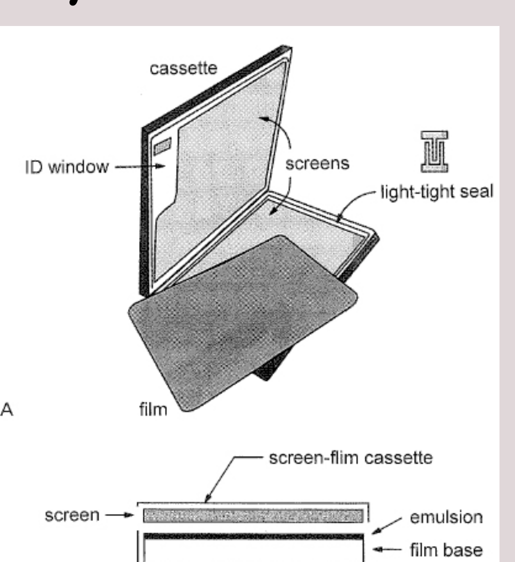 | 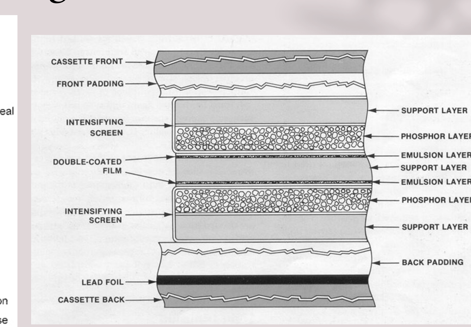 |
Intensifying Screen Mechanics5
- Used to reduce radiation exposure
- Film (AgBr) is sensitive to UV and blue light
- Intensifying screen makes the film 10-60 times more sensitive to x-rays
- Screens are placed on each side of the film (double coated film) to help increase image sharpness.
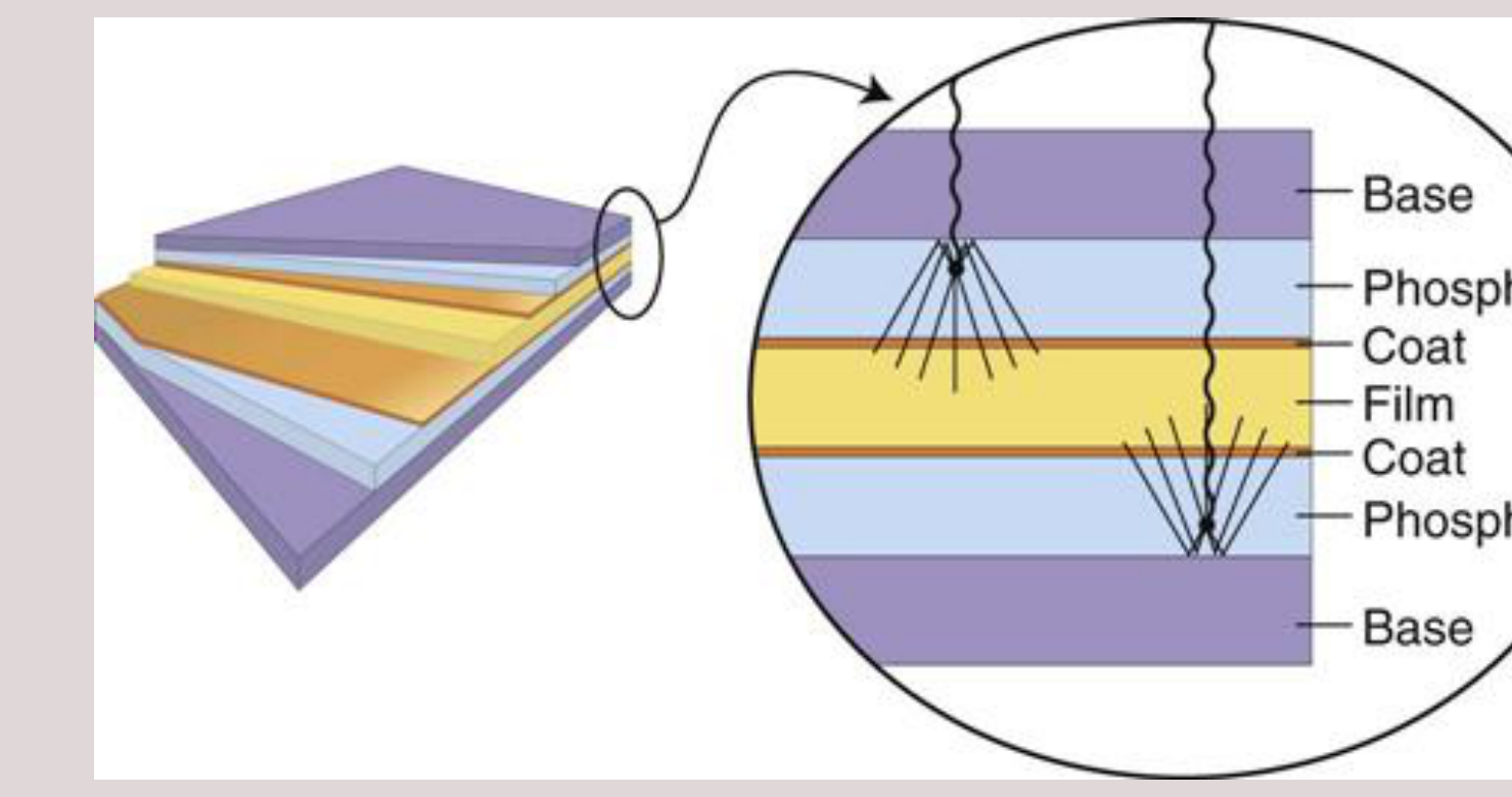
Phosphor Layer Composition
- Composed of phosphor crystals
- Inorganic salts
- calcium tungstate (CaWO): blue light
- lanthanum oxybromide (LaOBr): blue light
- gadolinium oxysulfide (GdOS): green light
- Rare earth elements
- Have better light conversion efficacy
- Lanthanum, gadolinium and yttrium
- Inorganic salts
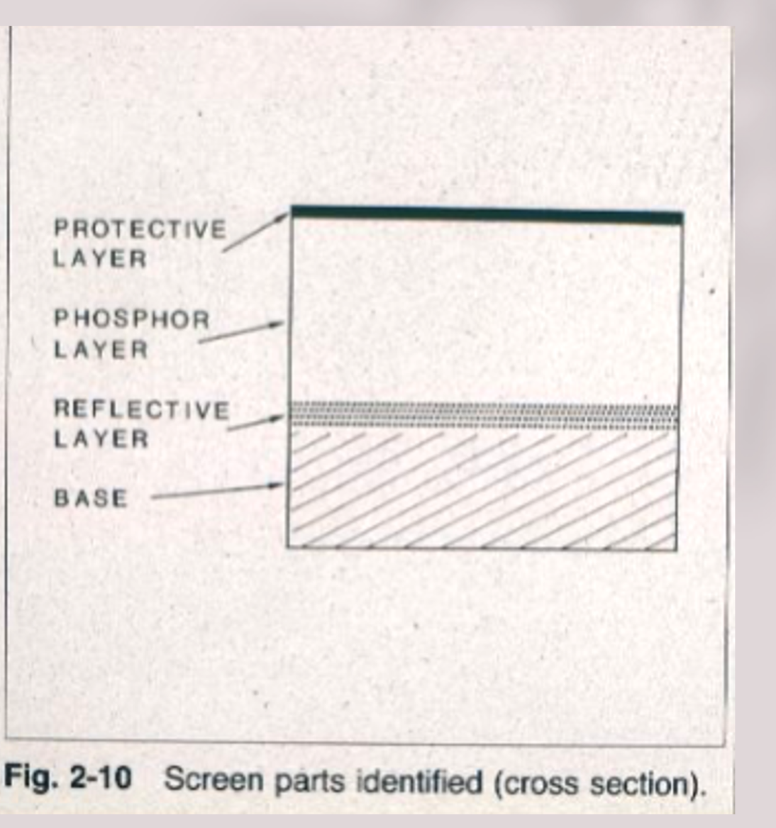
Base and Reflective Layers6
- Base = Polyester plastic that ~0.25 mm thick (mechanical support)
- Reflective layer reflects light emitted from the phosphor layer back toward the x-ray film
- This reflective base increases the light emission of the intensifying screen but also results in image fogging “unsharpness” because of the divergence of light rays reflected back to the film.
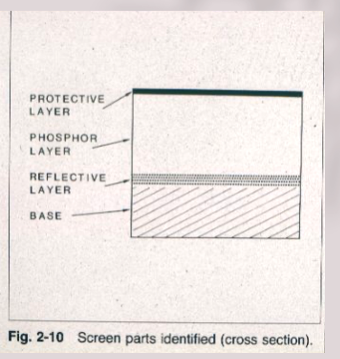
Protective Layer7
- Polymer coat (≤15 µm thick) is placed over the phosphor layer to protect the phosphor and to provide a surface that can be cleaned
Screen-Film Speed and Sensitivity8
Screen-Film Speed9
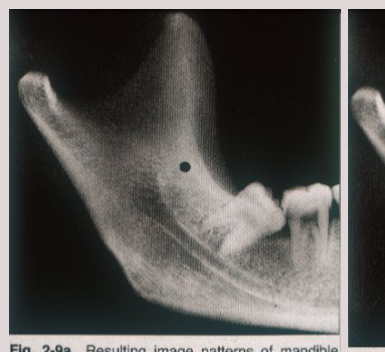
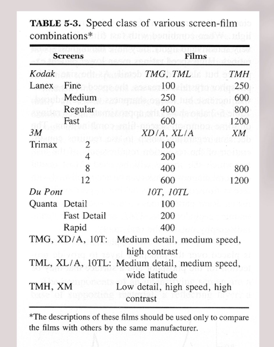
- Fast screen-films are used in dentistry (speed of 400 or more)
- They contain large phosphor crystals
- Thick
- Reduced radiation exposure
- Rapidly conversion of x-ray photons into visible light at the expense of decreased image sharpness
| Manufacturer | Screen | Film | Speed |
|---|---|---|---|
| Kodak | Lanex Fine | TMG, TML | 100 |
| TMH | 250 | ||
| Medium | 600 | ||
| Regular | 800 | ||
| Fast | 1200 | ||
| 3M | Trimax 2 | XD/A, XL/A | 100 |
| 4 | 200 | ||
| 8 | XM | 800 | |
| 12 | 1200 | ||
| Du Pont | Quanta Detail | 10T, 10TL | 100 |
| Fast Detail | 200 | ||
| Rapid | 400 |
TMG, XD/A, 10T: Medium detail, medium speed, high contrast TML, XL/A, 10TL: Medium detail, medium speed, wide latitude TMH, XM: Low detail, high speed, high contrast
The descriptions of these films should be used only to compare the films with others by the same manufacturer.
Fig. 2-9b: On film/screen combination.
Clinical Projections and Techniques1011
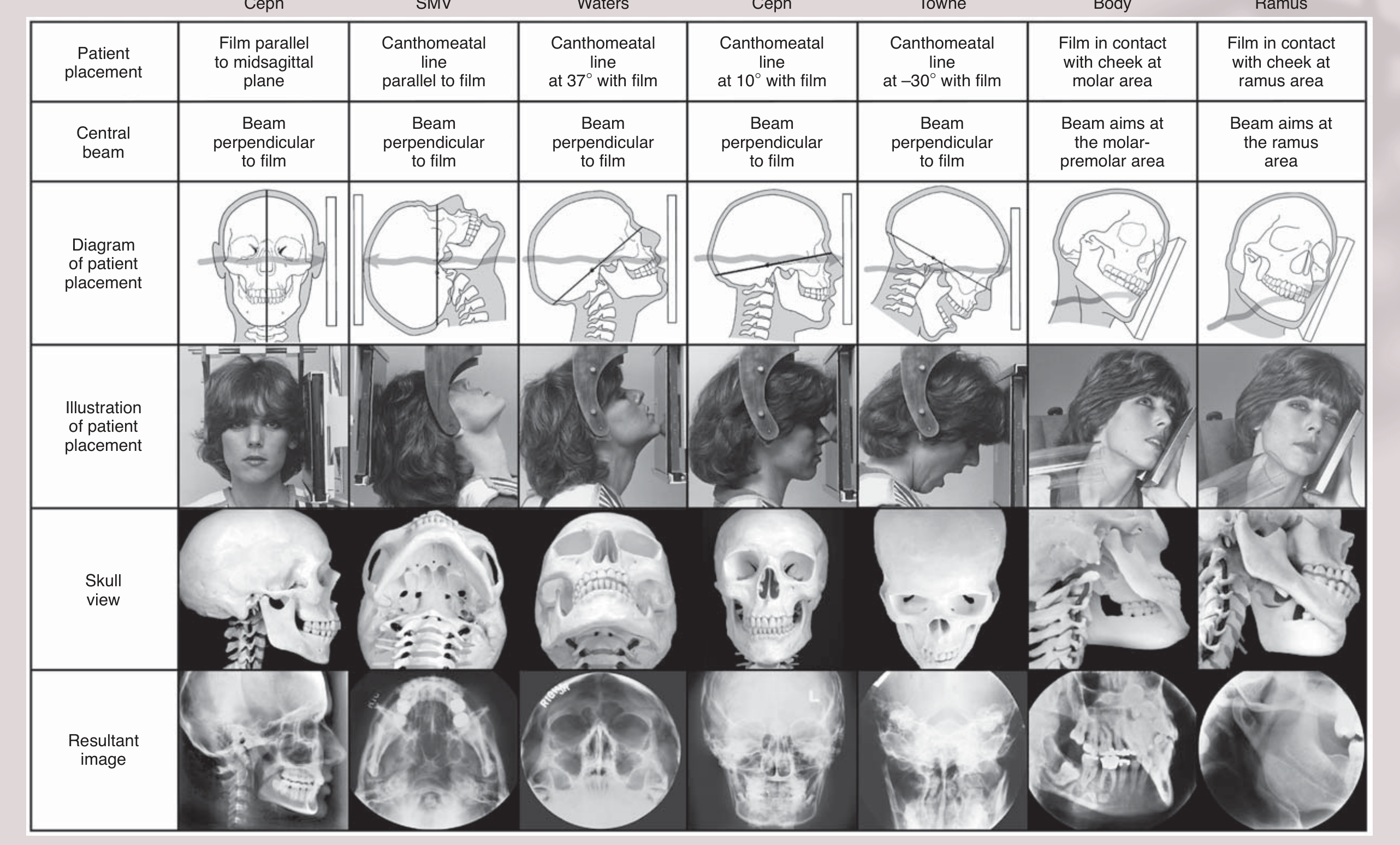
Common Extra-oral Views
| Patient placement | Lateral Ceph | SMV | Waters | PA Ceph | Reverse Towne | Oblique Lateral |
|---|---|---|---|---|---|---|
| Film parallel to midsagittal plane | Canthomeatal line parallel to film | Canthomeatal line at 37° with film | Canthomeatal line at 10° with film | Canthomeatal line at –30° with film | Film in contact with cheek at molar area | Beam in contact with cheek at ramus area |
| Central beam | Beam perpendicular to film | Beam perpendicular to film | Beam perpendicular to film | Beam perpendicular to film | Beam aims at the molar-premolar area | Beam aims at the ramus area |
| Diagram of patient placement | ||||||
| Illustration of patient placement | ||||||
| Skull view | ||||||
| Resultant image | ||||||
Lateral Cephalogram12
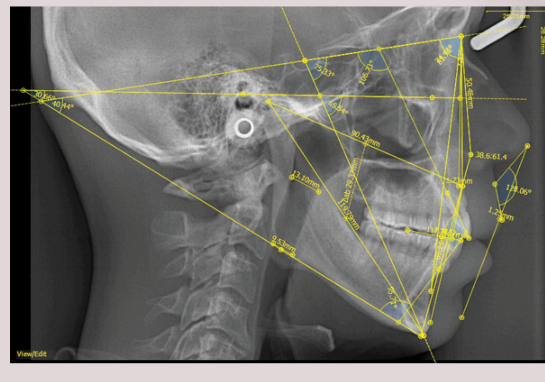
Overview13
- Cephalogram = standardised view
- Reproducible
- True Lateral Skull projection
- Midsagittal line parallel to film
- X-ray beam perpendicular to film
- Soft tissue definition achieved by aluminium wedge filter
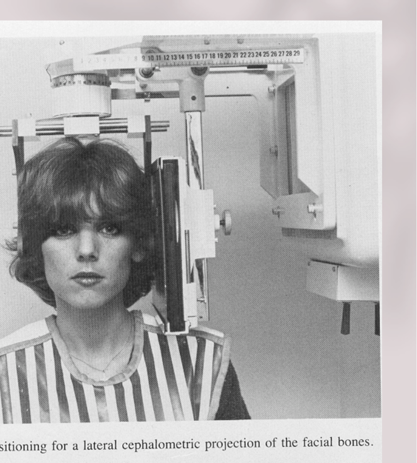
Indications
- Orthodontic and orthognathic assessment (pre, peri and post)
- Anteroposterior (AP) relationships between the maxilla, mandible, and cranial base
- Skeletal, dental and soft tissue relationships
- Other (less common)
- Skull bone disorder (Paget’s, Multiple myeloma, hyperparathyroidism etc.)
- Paranasal sinus diseases
- Trauma
- Cranial base and Midface
Cephalostat
CEPHALOSTAT
Lateral Cephalogram Positioning14
- Patient placed in cephalostat
- Midsagittal line parallel to receptor
- Frankfort plane horizontal to floor
- Markers – forehead / infraorbital rests, and ear rods
- Teeth in maximum intercuspation (MIP) OR mandible in most retruded position with posterior teeth occluding
- Lips fully rested (closed or open)
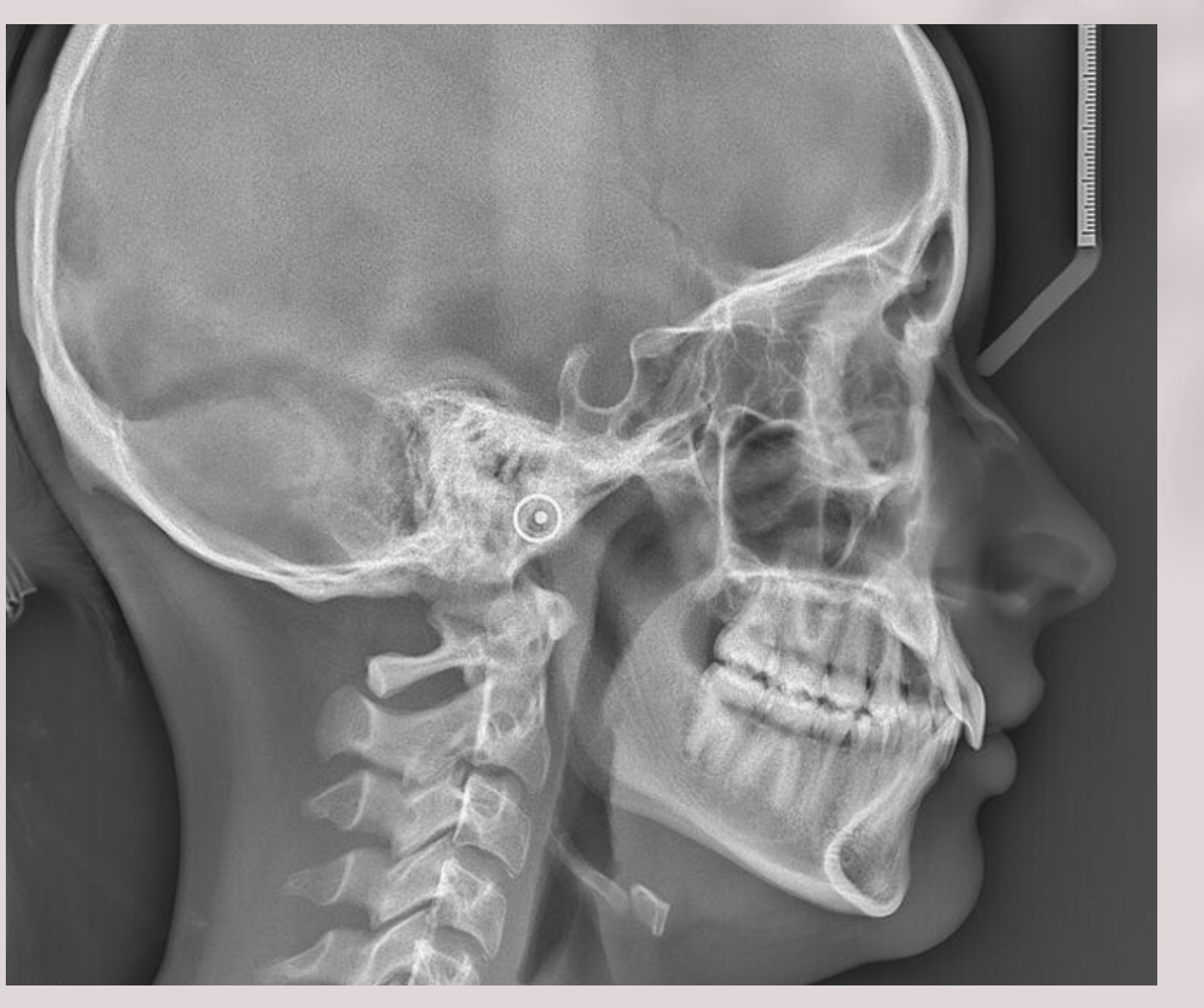
Lateral Cephalogram Anatomy and Landmarks15
Lat Ceph Landmarks
- Orbital Roof
- Greater Sphenoid Wing
- Sella Turcica
- Condyles
- Ramus
- Frontal Sinus
- Frontal Sinus
- Nasal Bone
- Maxillary Sinus
- Maxilla
- Mandible
- Cervical spine
- Soft palate
- tongue
Anatomy and Landmarks Labelled
- Pterygoid plates
- Clivus
- Pterygoid spine
- Pterygomaxillary fissure
- Posterior clinoid processes
- Sella turcica
- Anterior clinoid processes
- Sphenoid sinus
- Planum sphenoidale
- Posterior maxillary sinus
- Roof of orbit
- Pterygoid maxilla
- Ethmoid air cells
- Nasion
- Nasal bone
- Lens of eye
- Lower eyelid
- Frontal process of zygoma
- Inferior rim of orbit
- Floor of orbit
- Zygomatic process of maxilla
- Anterior nasal spine
- Point A
- Hard palate
- Tooth bud
- Point B
- Base of middle cranial fossa
- External auditory meatus
- Mastoid air cells
- Mastoid process
- Occipital condyle
- Posterior arch of atlas
- Anterior arch of atlas
- Dens axis
- Posterior pharyngeal wall
- Earlobe
- Salpingopharyngeal fold
- Superior border of inferior turbinate
- Soft palate
- Inferior border of zygomatic arch
- Dorsum of tongue
- Hyoid bone
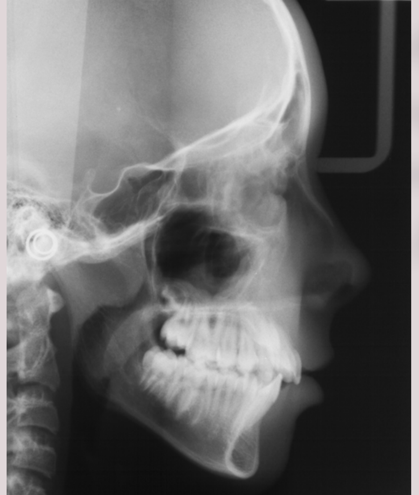
Postero-Anterior and Frontal Projections1617181920
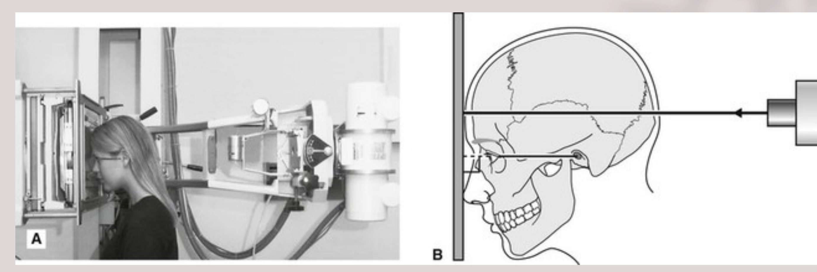
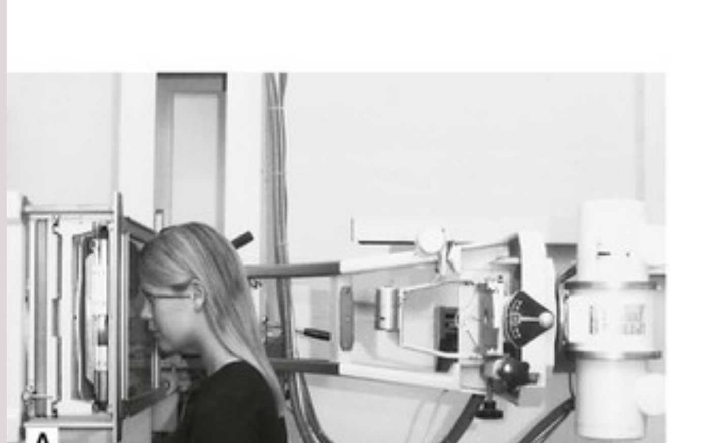
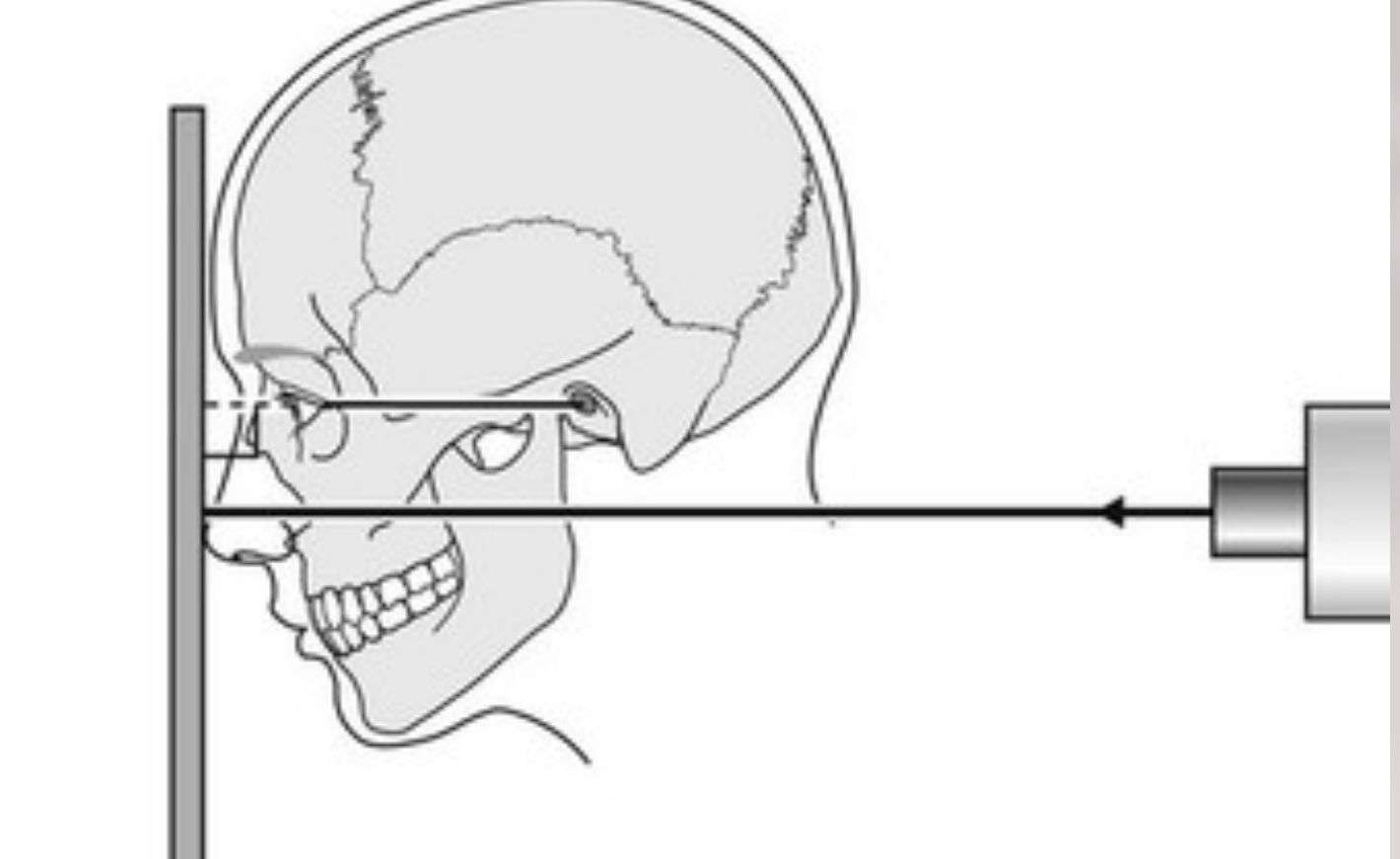
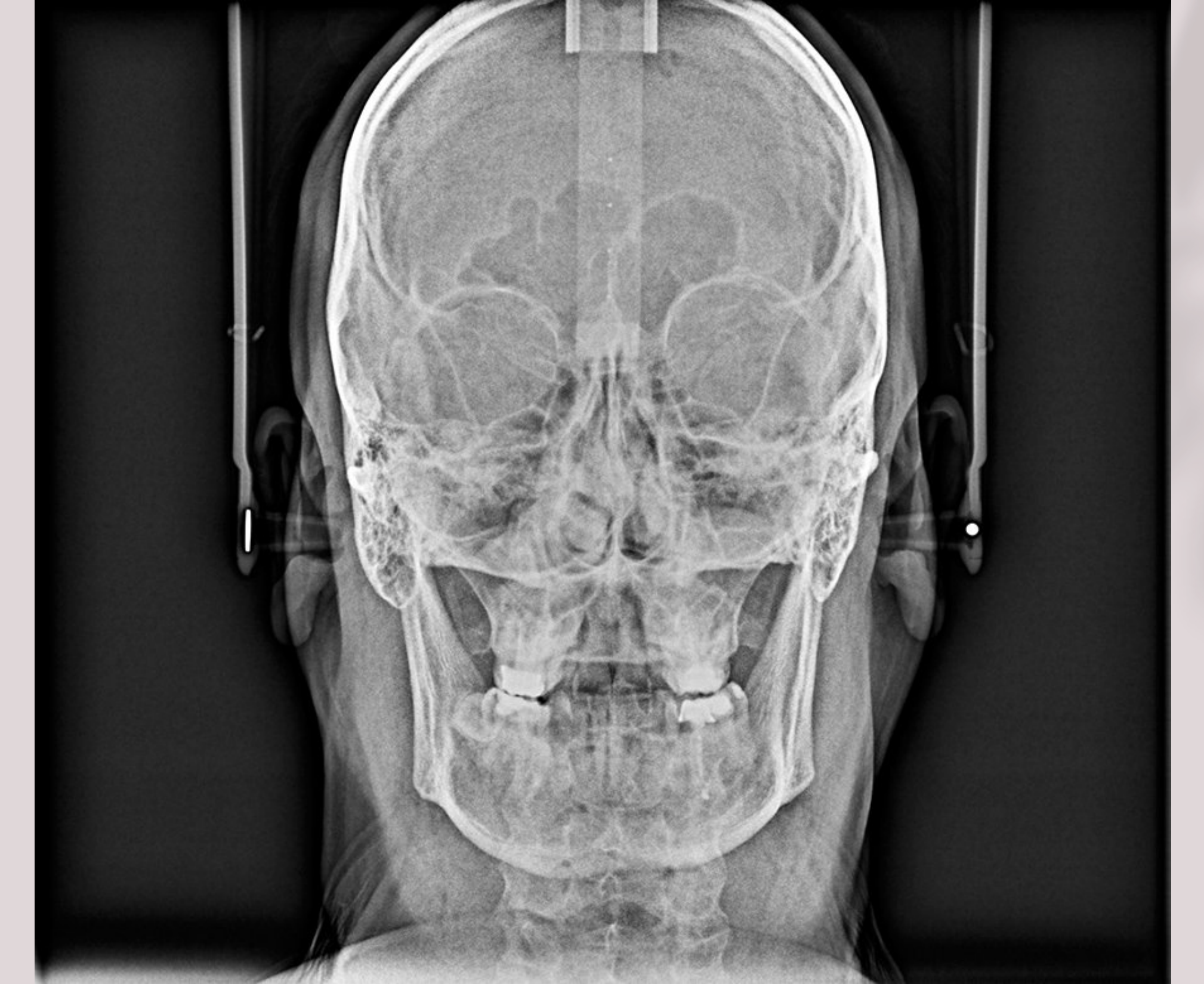
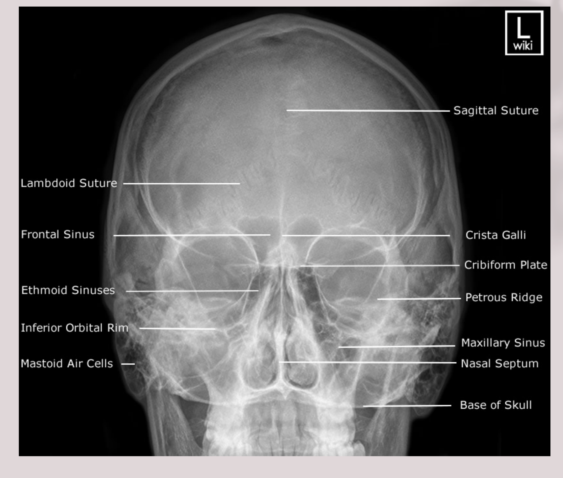
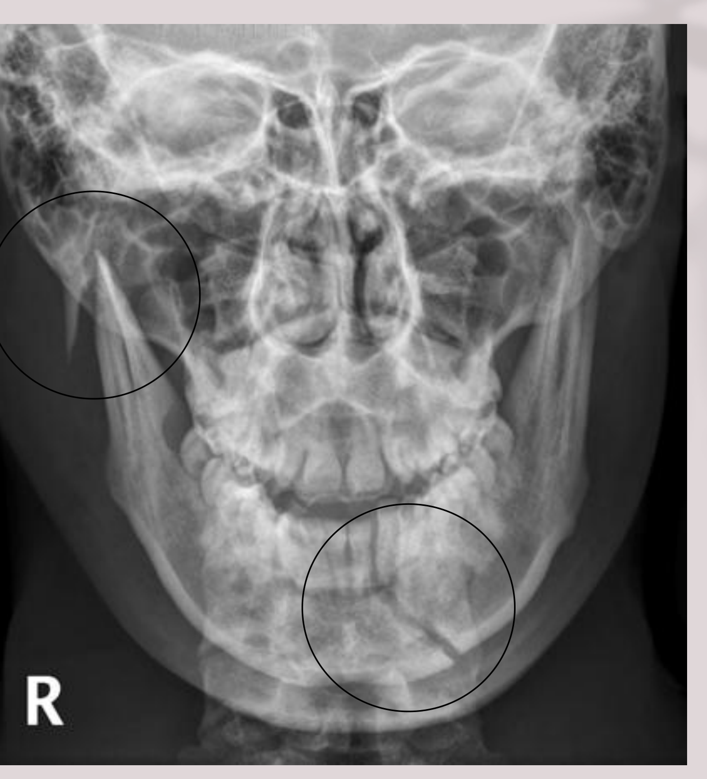
- Frontal / PA Ceph, PA Skull, PA Mandible, Rotated PA
 |  |  |
 |  |  |
Indications21
- PA Ceph: Facial asymmetry (developmental or traumatic)
- PA Skull
- Trauma
- Paranasal sinuses
- Skull bone disorders (Paget’s disease, Multiple myeloma, and Hyperparathyroidism)
- PA Mandible
- Fractures (post 1/3 body, angles, rami, and low condylar necks)
Patient positioning
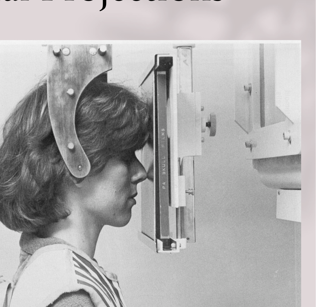
- Canthomeatal line 0 to +10°
- 0° for PA skull, PA mandible
- +10° for PA CEPH
- Chin and forehead touch film
- Beam perpendicular to film horizontal
Submentovertex Projection2223
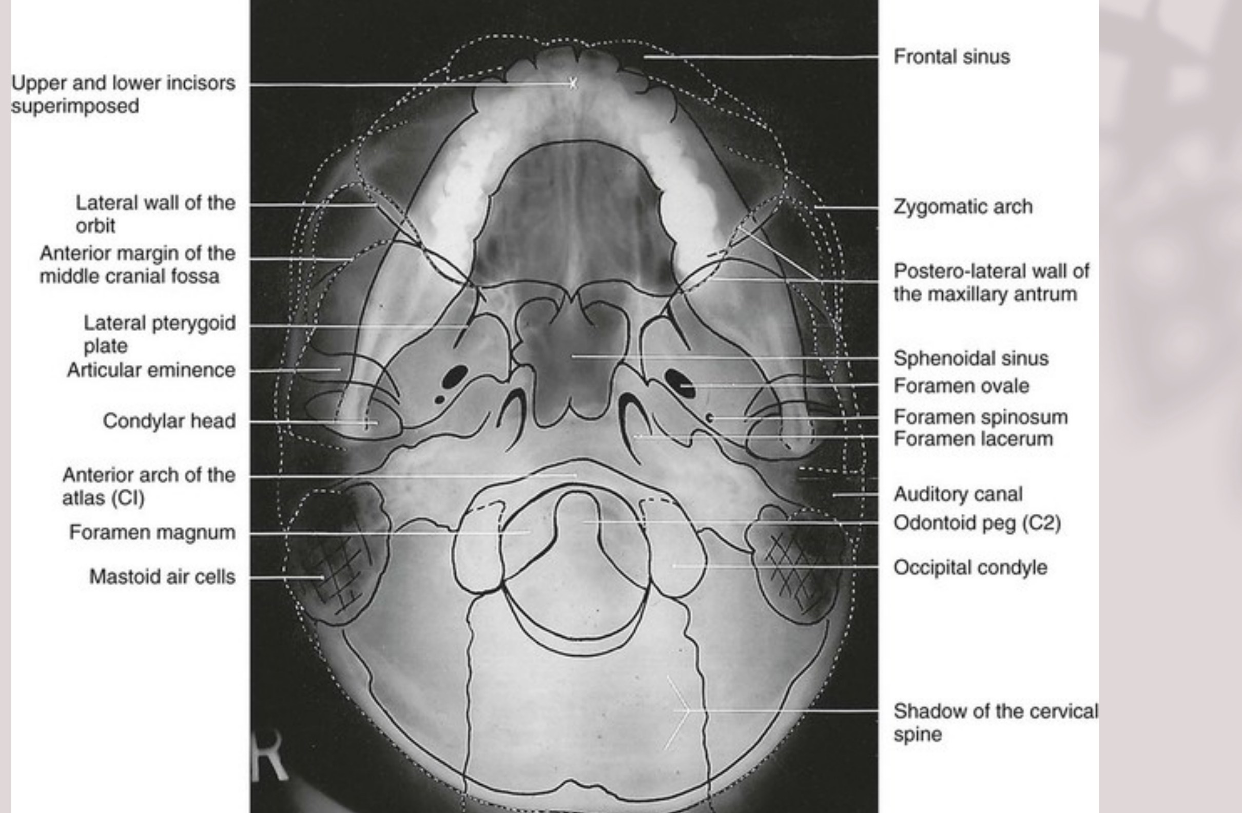
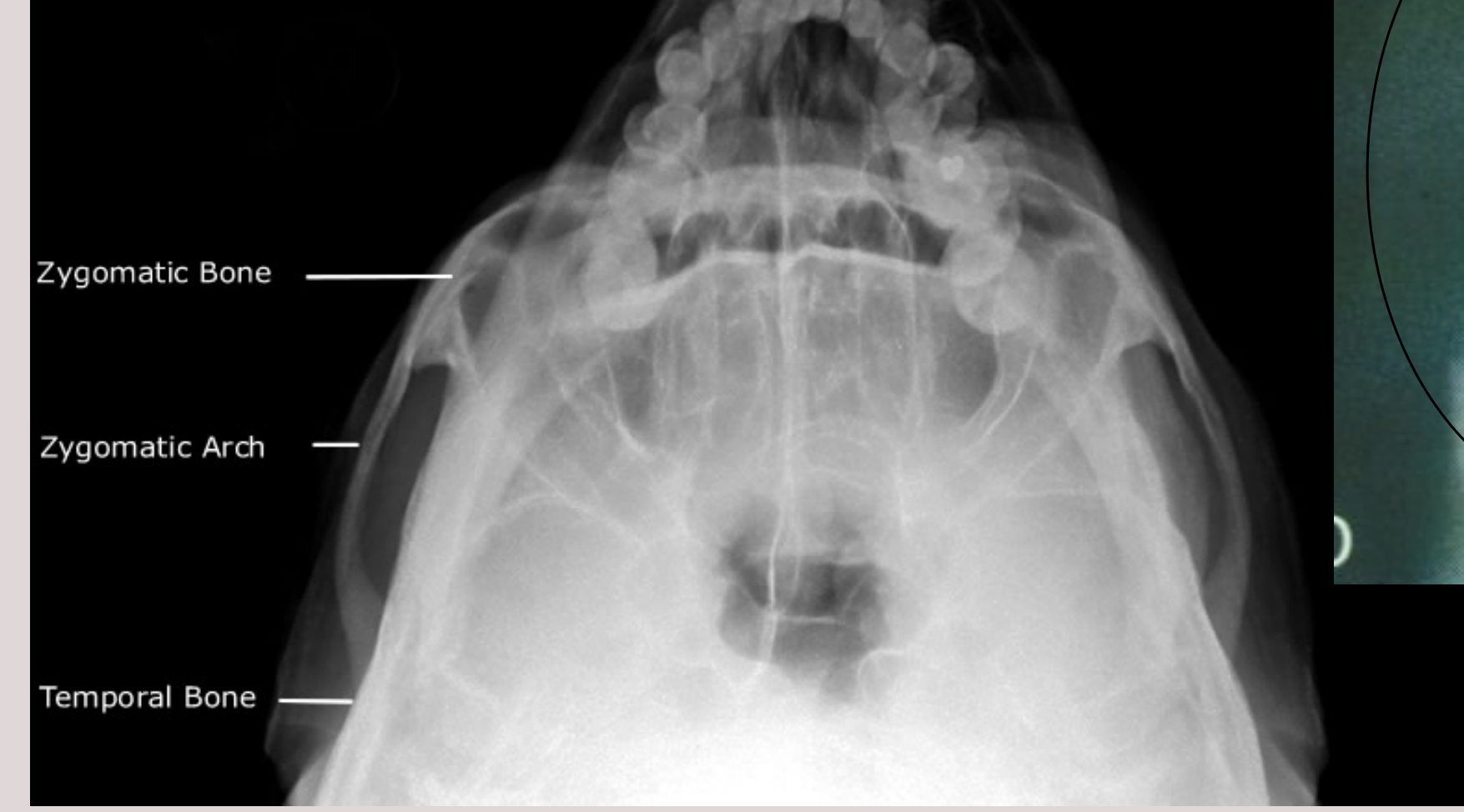
SMV (Submentover)
 |  |
 |
Axial plane24
 |  |
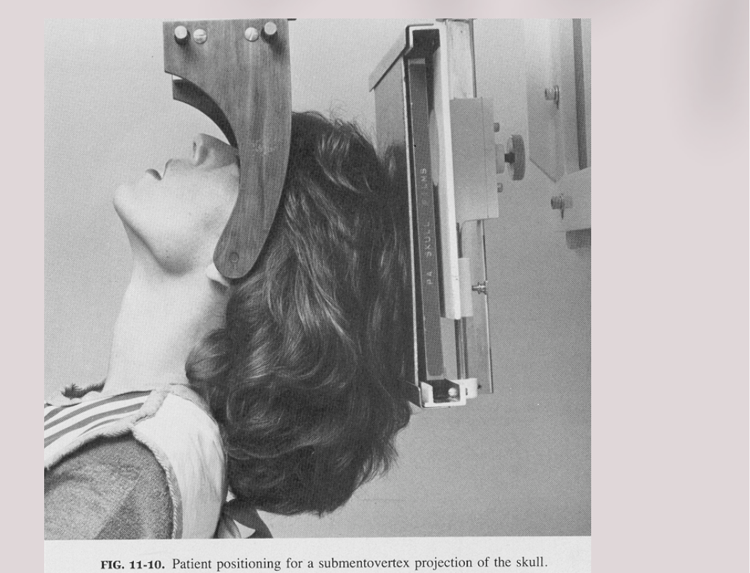 |
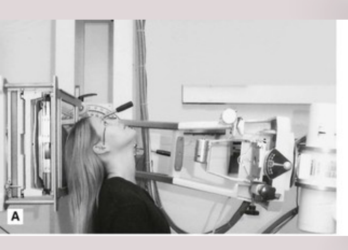
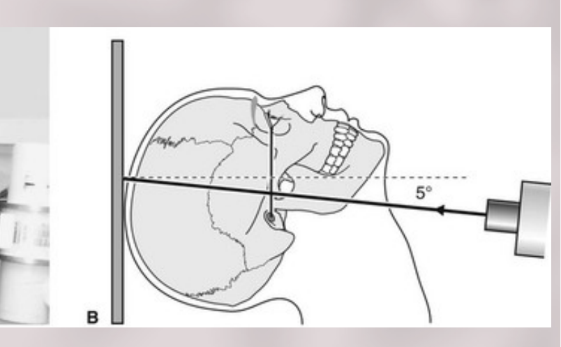
Positioning
- Chin up
- Canthomeatal line parallel to film.
- X-ray beam perpendicular to film (or up to -5°)
Indications
- Zygomatic arch fractures
- Thickness of body of mandible
- Skull base
Contraindicated in patients with suspected neck injuries, especially suspected fracture of the odontoid peg.
- Mandibular Symphysis
- Zygomatic Bone
- Zygomatic Arch
- Temporal Bone
Waters View2526
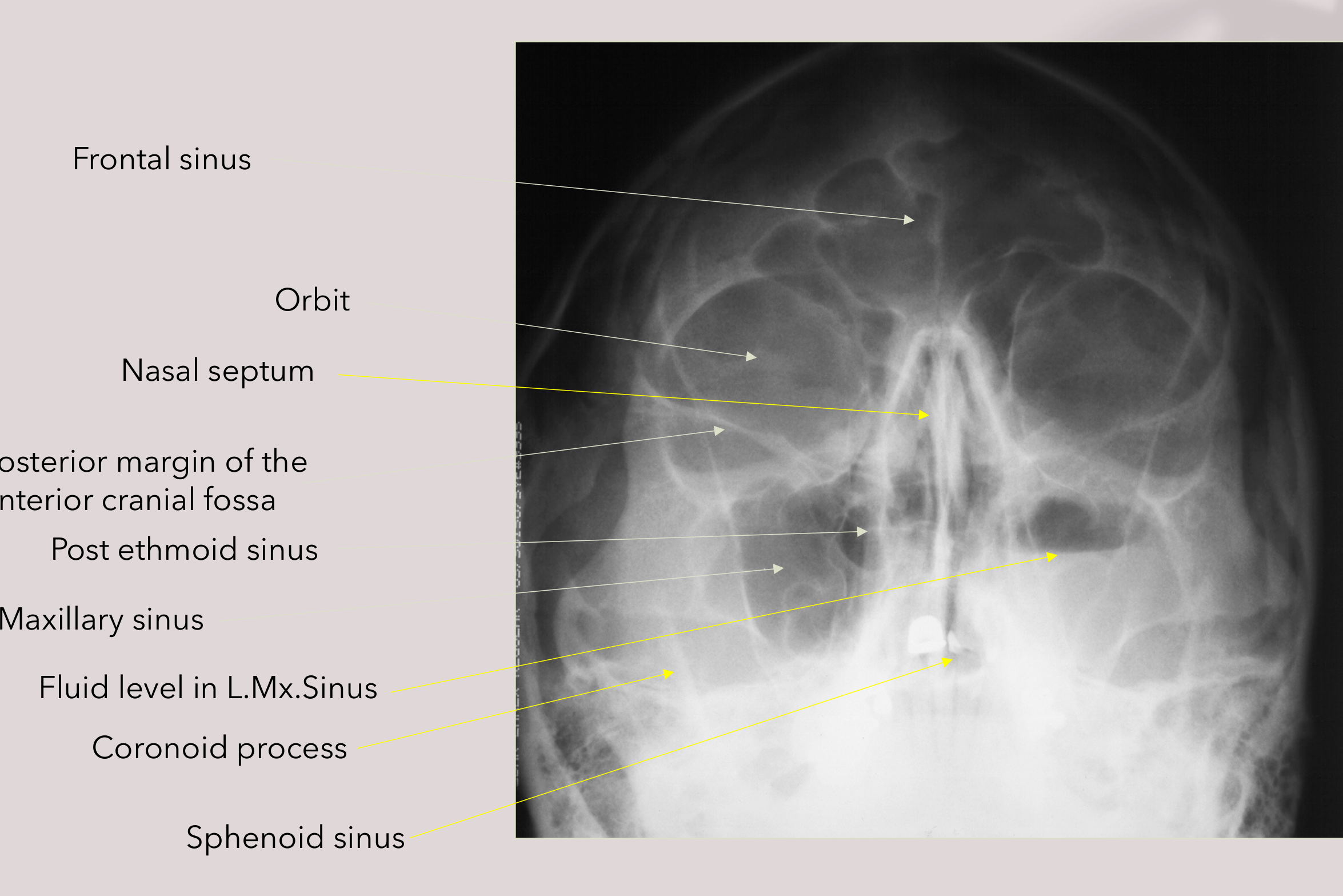 | 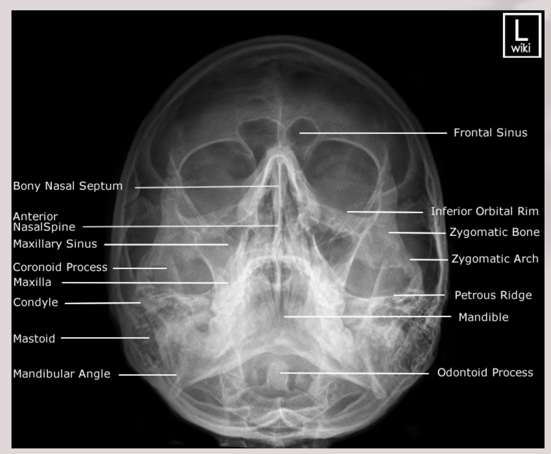 |
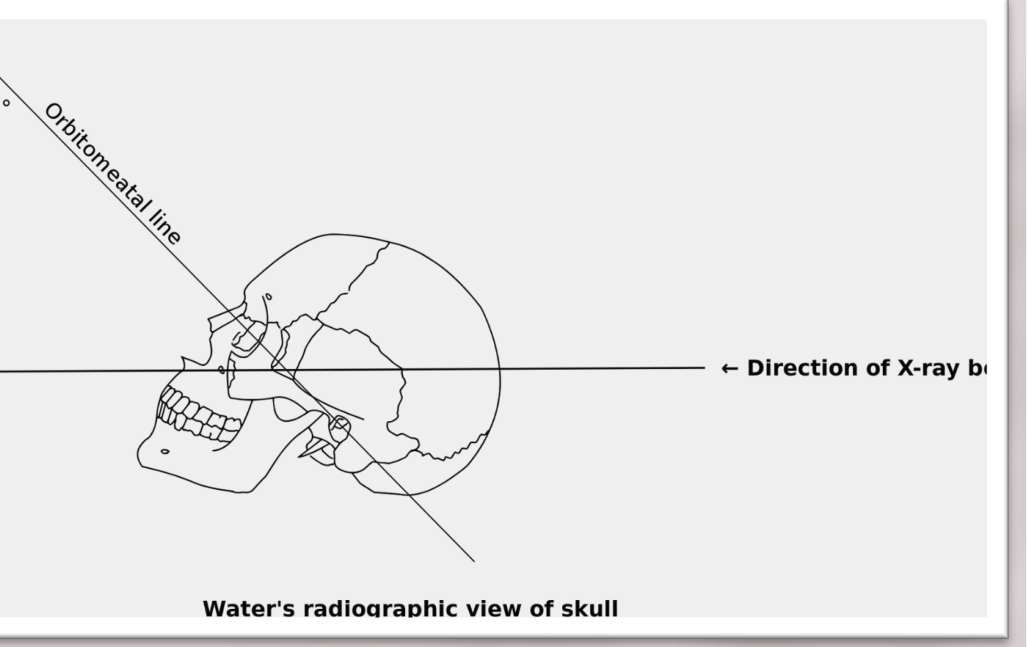
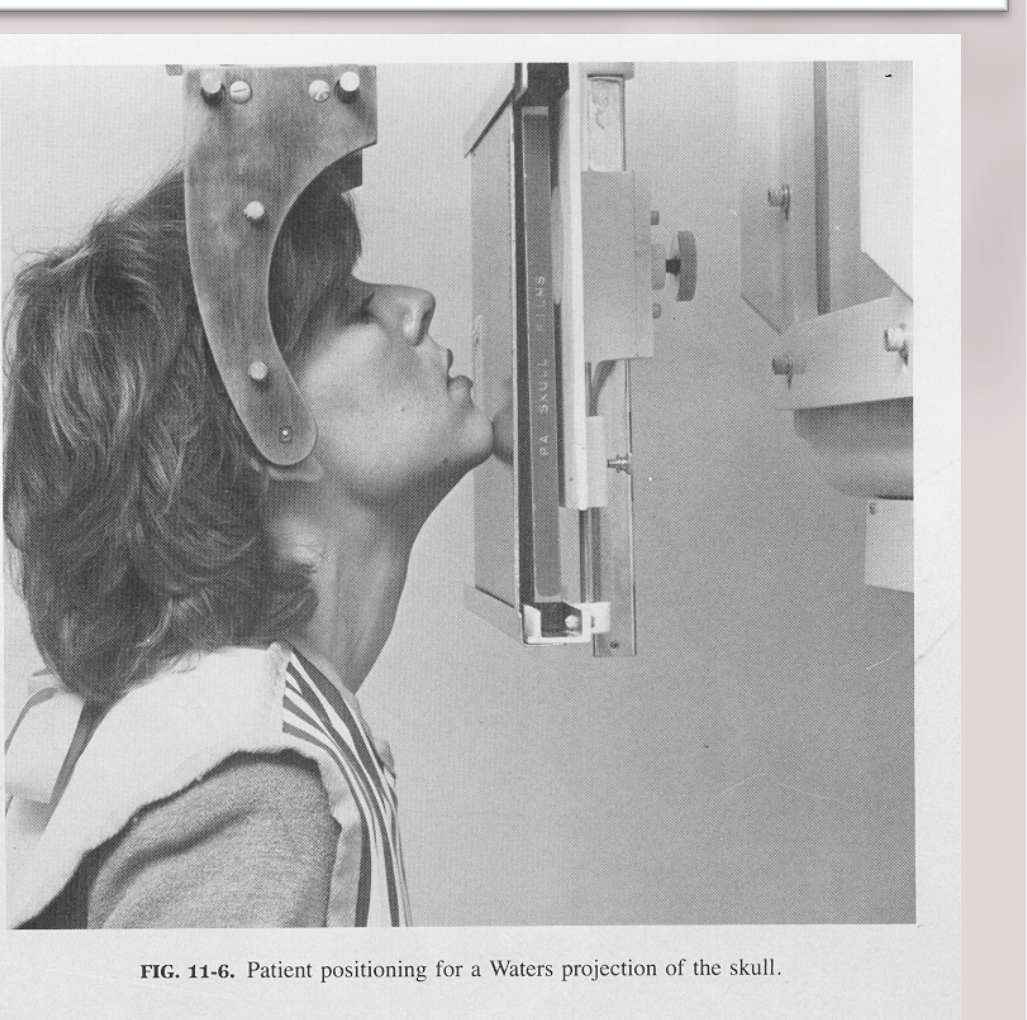
Positioning27
- Canthomeatal line at 37° to 45° to film
- X-ray beam perpendicular to film (standard)
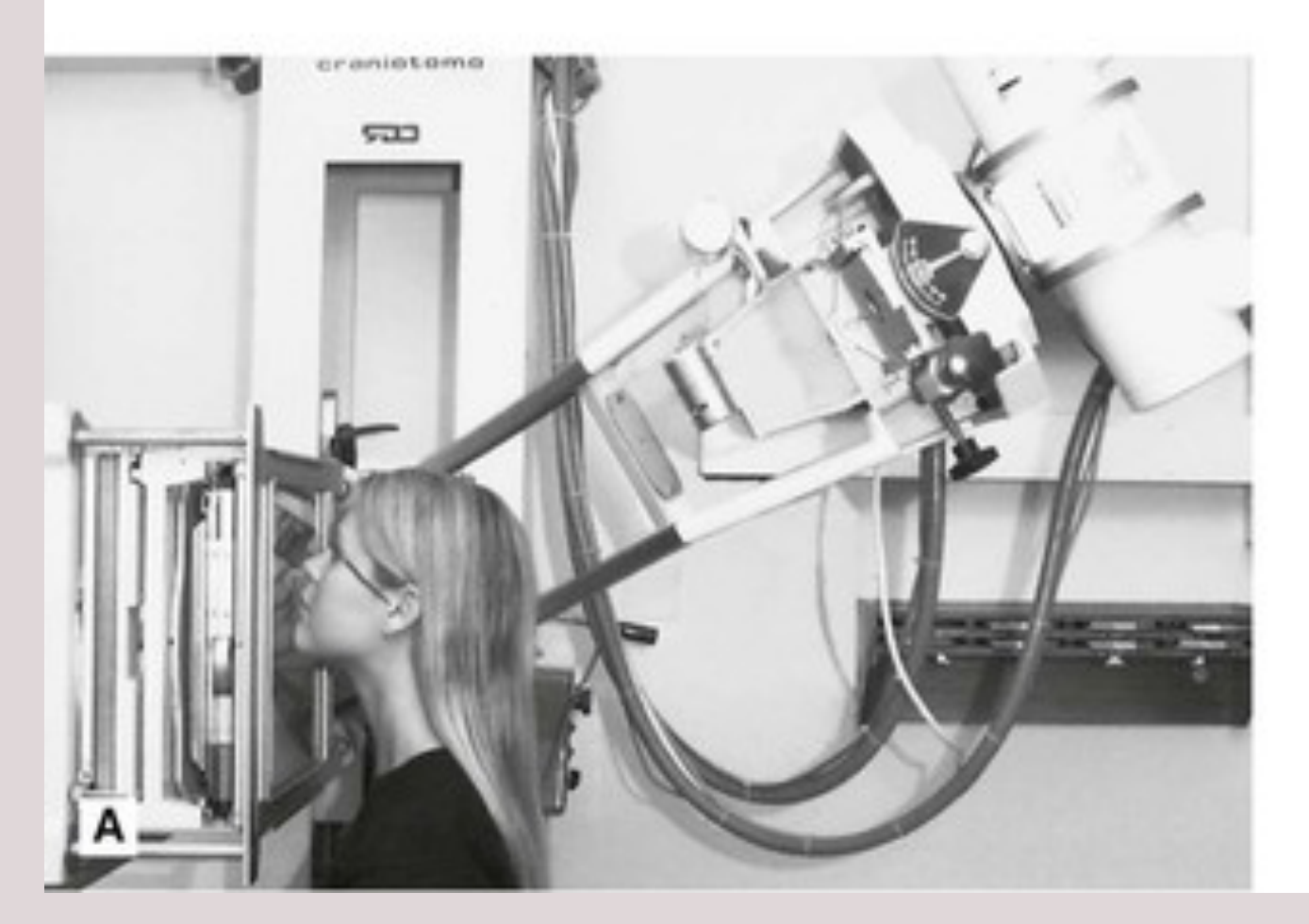
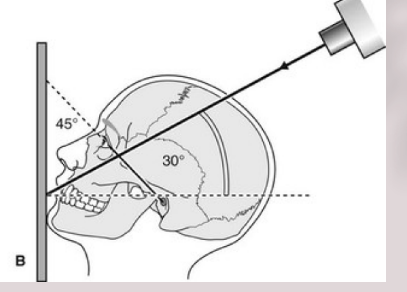
- Modified Water’s view aka ‘30° Occipitomeatal’
- X-ray beam at +30° to horizontal / floor
 |  |
Indications
- Paranasal sinuses (maxillary, frontal, and ethmoid).
- If assessing the sphenoid sinus, image needs to be taken with mouth open.
- Midface fractures (Le Fort I/II/III, zygomatic complex, naso-ethmoidal complex, and orbital blow-out).
- If midface fracture is suspected. Both standard and modified views are required for traditional imaging.
45° Orbitomeatal line Radiographic plate ← Direction of X-ray beam
Water’s radiographic view of skull
FIG. 11-6. Patient positioning for a Waters projection of the skull.
Occipitomental Variations
30° Occipitomental View (30° OM)28
A
B
 |  |
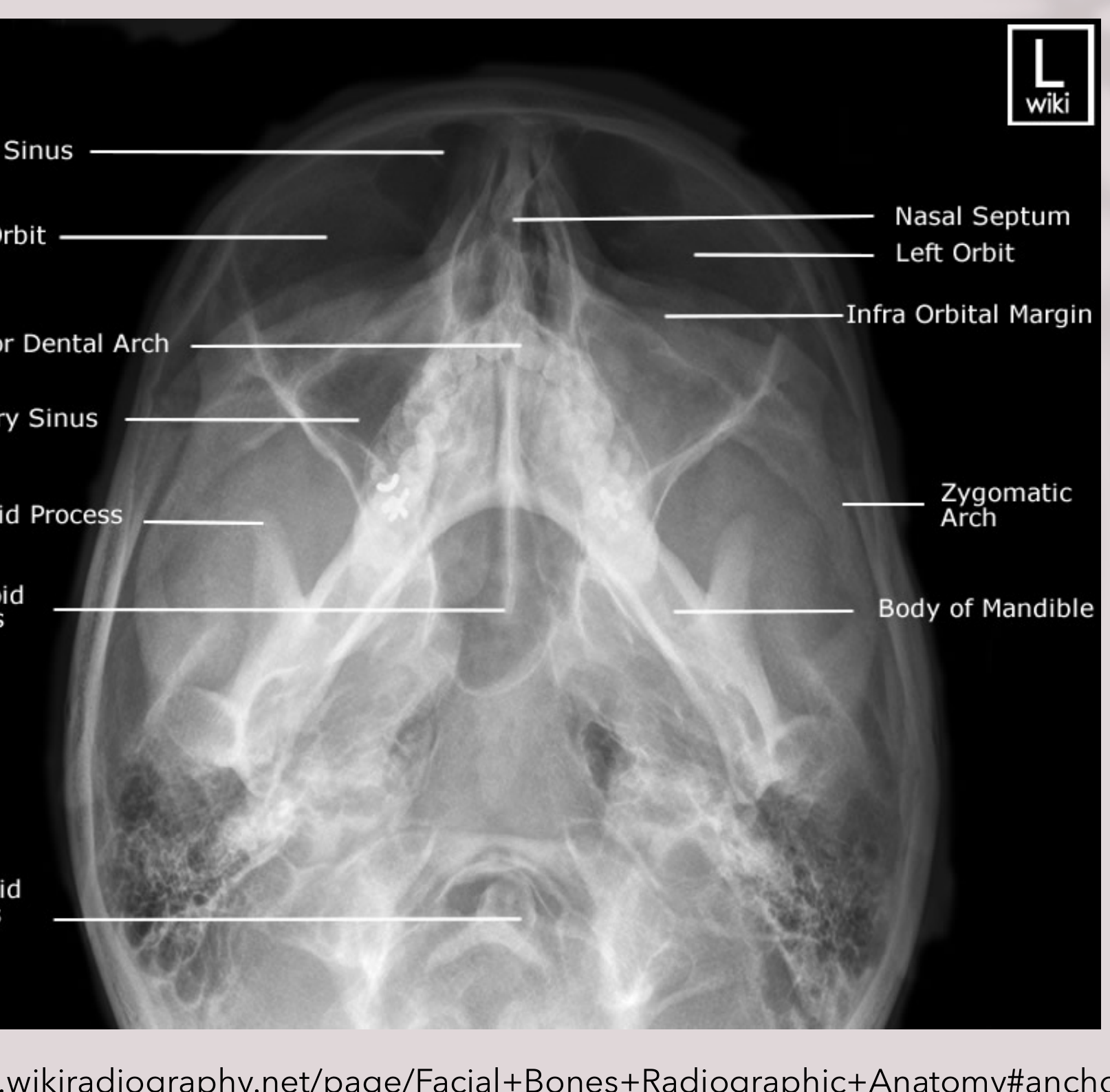
30° Waters View - Alternative Technique29
Reverse Towne View3031
 |  |
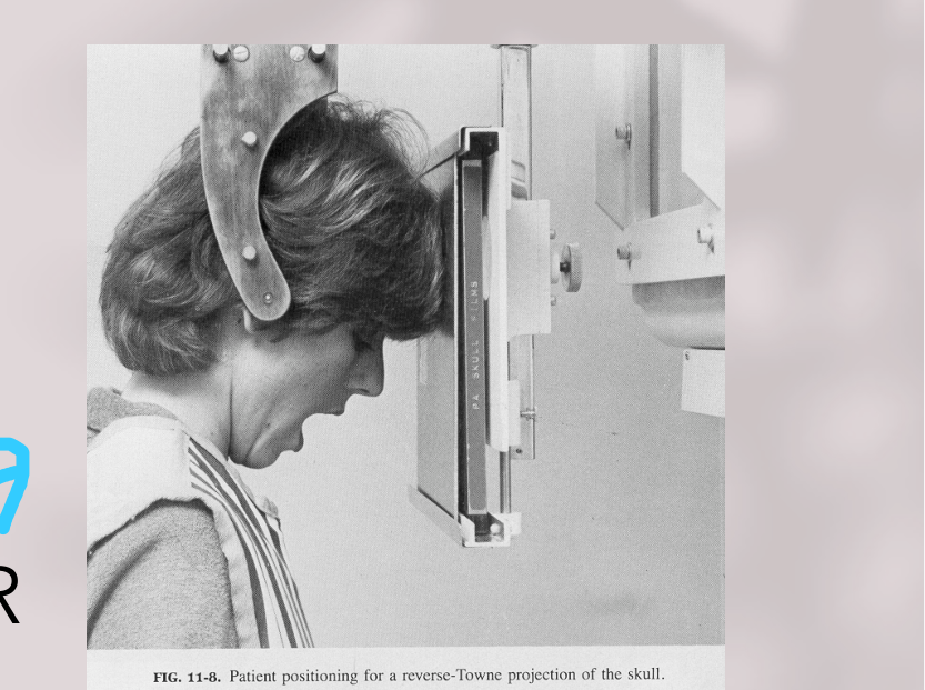
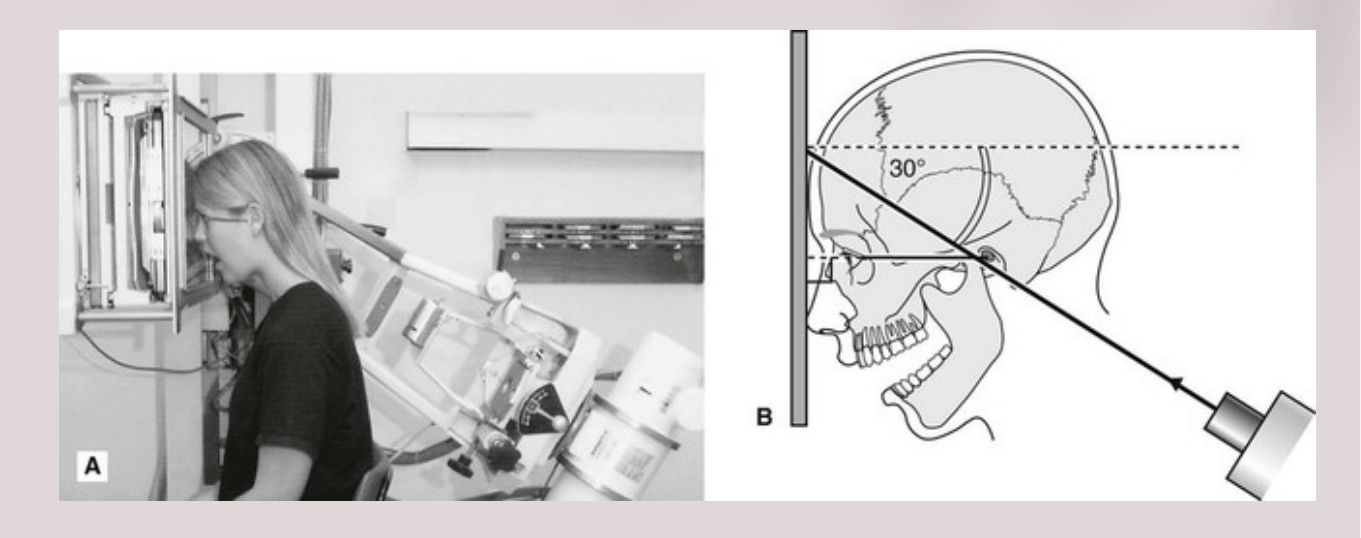
Patient Positioning32
- Canthomeatal line -30° & x-ray beam horizontal; OR
- Canthomeatal line horizontal & x-ray beam -30°
- Jaws always open!
 |  |
Indications
- Condylar neck fractures
- TM Joint disorder
Oblique Lateral Radiography33
 |  |
 |  |
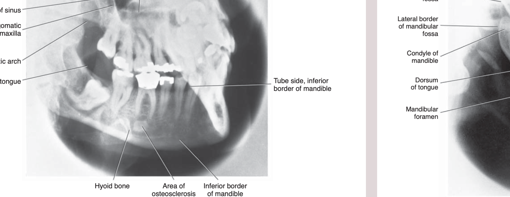
Mandibular Body34
FIG. 12-7 Anatomic landmarks identified in the oblique lateral projection of the mandibular body.
- Hard palate
- Inferior border of orbit
- Posterior wall of sinus
- Posterior wall of zygomatic process of maxilla
- Inferior border of zygomatic arch
- Dorsum of tongue
- Tube side, inferior border of mandible
- Inferior border of mandible
- Area of osteosclerosis
- Hyoid bone
 | 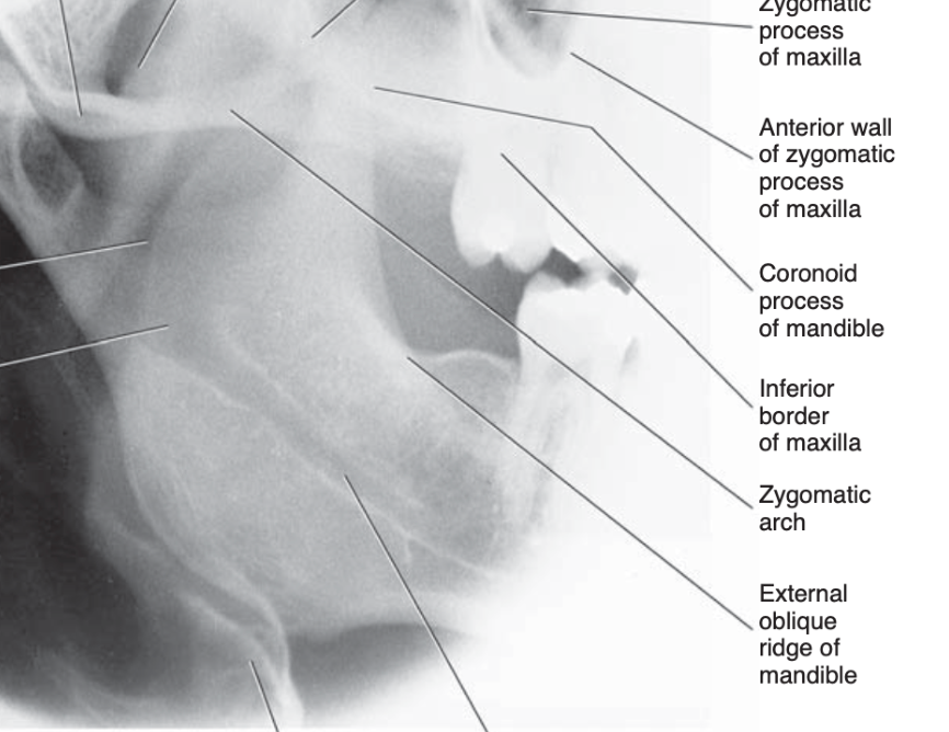 |
Mandibular Ramus
FIG. 12-8 Anatomic landmarks identified in the oblique lateral projection of the mandibular ramus.
- Articular eminence
- Dorsum of soft palate
- Posterior wall of maxillary sinus
- Hard palate
- Zygomatic process of maxilla
- Anterior wall of zygomatic process of maxilla
- Coronoid process of mandible
- Inferior border of maxilla
- Zygomatic arch
- External oblique ridge of mandible
- Mandible canal
- Hyoid bone
- Mandibular foramen
- Dorsum of tongue
- Condyle of mandible
- Lateral border of mandibular fossa
- Medial border of mandibular fossa
References35
- Oral Radiology Principles and Interpretation-White and Pharoah
- Essentials of Dental Radiography and Radiology – Whaites and Drage
- http://www.wikiradiography.net/page/Facial+Bones+Radiographic+Anatomy
Footnotes
-
Original PDF page 1: L9 Cephs and Other EO Views, p.1 ↩
-
Original PDF page 2: L9 Cephs and Other EO Views, p.2 ↩
-
Original PDF page 3: L9 Cephs and Other EO Views, p.3 ↩
-
Original PDF page 4: L9 Cephs and Other EO Views, p.4 ↩
-
Original PDF page 5: L9 Cephs and Other EO Views, p.5 ↩
-
Original PDF page 7: L9 Cephs and Other EO Views, p.7 ↩
-
Original PDF page 8: L9 Cephs and Other EO Views, p.8 ↩
-
Original PDF page 10: L9 Cephs and Other EO Views, p.10 ↩
-
Original PDF page 9: L9 Cephs and Other EO Views, p.9 ↩
-
Original PDF page 11: L9 Cephs and Other EO Views, p.11 ↩
-
Original PDF page 12: L9 Cephs and Other EO Views, p.12 ↩
-
Original PDF page 14: L9 Cephs and Other EO Views, p.14 ↩
-
Original PDF page 13: L9 Cephs and Other EO Views, p.13 ↩
-
Original PDF page 15: L9 Cephs and Other EO Views, p.15 ↩
-
Original PDF page 18: L9 Cephs and Other EO Views, p.18 ↩
-
Original PDF page 20: L9 Cephs and Other EO Views, p.20 ↩
-
Original PDF page 21: L9 Cephs and Other EO Views, p.21 ↩
-
Original PDF page 22: L9 Cephs and Other EO Views, p.22 ↩
-
Original PDF page 23: L9 Cephs and Other EO Views, p.23 ↩
-
Original PDF page 24: L9 Cephs and Other EO Views, p.24 ↩
-
Original PDF page 19: L9 Cephs and Other EO Views, p.19 ↩
-
Original PDF page 26: L9 Cephs and Other EO Views, p.26 ↩
-
Original PDF page 27: L9 Cephs and Other EO Views, p.27 ↩
-
Original PDF page 25: L9 Cephs and Other EO Views, p.25 ↩
-
Original PDF page 29: L9 Cephs and Other EO Views, p.29 ↩
-
Original PDF page 30: L9 Cephs and Other EO Views, p.30 ↩
-
Original PDF page 28: L9 Cephs and Other EO Views, p.28 ↩
-
Original PDF page 31: L9 Cephs and Other EO Views, p.31 ↩
-
Original PDF page 32: L9 Cephs and Other EO Views, p.32 ↩
-
Original PDF page 34: L9 Cephs and Other EO Views, p.34 ↩
-
Original PDF page 35: L9 Cephs and Other EO Views, p.35 ↩
-
Original PDF page 33: L9 Cephs and Other EO Views, p.33 ↩
-
Original PDF page 37: L9 Cephs and Other EO Views, p.37 ↩
-
Original PDF page 36: L9 Cephs and Other EO Views, p.36 ↩
-
Original PDF page 38: L9 Cephs and Other EO Views, p.38 ↩