Cutting Out the Complexity of Class 2 Posterior Composites1
Front Matter23
We are learning on Noongar land
The University of Western Australia
Material used in this recording may have been reproduced and communicated to you by or on behalf of The University of Western Australia in accordance with section 113P of the Copyright Act 1968.
Unless stated otherwise, all teaching and learning materials provided to you by the University are protected under the Copyright Act and is for your personal use only. This material must not be shared or distributed without the permission of the University and the copyright owner/s.
The University of Western Australia
Dr. Amit Gurbuxani MRACDS(DPH), BDSc, MDPPH, FPFA, FICD, FADI
Introduction and Overview
Why Do Most Class II Composites Fail4
Why do most Class II composites fail?
Factors Influencing Clinical Success56
Factors that can influence the clinical success of Class II composite restorations:
Lecturer — Failure Mechanisms
The matrix creates the contact, not the composite. If the matrix moves, the restoration is likely to fail, and many open contacts originate before composite placement because the matrix was not stabilized or adapted correctly.
- Deep subgingival bonding to dentine or cementum is weaker and breaks down more quickly.
- Other failure mechanisms include recurrent caries, marginal gaps, moisture contamination, inadequate curing, food impaction at open gingival margins, voids, and overhangs.
- Patient characteristics
- Tooth preparation
- Matrix utilization
- Composite composition — dentin bonding
Today I’m going to show you how almost all of these failures come from only four critical steps.
Lecturer — Predictable Technique
Predictable Class II composite results depend less on choosing a particular brand or matrix system than on following a consistent technique.
- Use effective isolation and prepare only diseased or unsupported tooth structure.
- Check occlusion before preparation and pre-wedge where appropriate.
- Place and adapt the matrix carefully, seal the gingival margin with correct wedging, and build the proximal wall before completing occlusal anatomy.
- Cure sufficiently, then finish, polish, and check occlusion.
Class II – Direct Posterior Composites
Size and Location of Restoration789
- The position of the tooth in the arch and the size of the cavity have been shown to be a factor in the success of a restoration. One study found the risk of failure in the molar area to be twice as high as for premolars,¹⁰ while another study placed the failure rate in lower molars as three times that of the upper premolars.¹¹ Multi-surfaced restorations are also more prone to failure than single surface restorations. A study calculated that for every surface added to the restoration, a 40% increase in the failure rate resulted.¹⁰
Opdam NJ, Bronkhorst EM, Roeters JM, Loomans BA. Longevity and reasons for failure of sandwich and total-etch posterior composite resin restorations. J Adhes Dent. 2007;9(5):469-475.
Lecturer — Molar Failure Factors
The higher failure risk in molars was attributed to their loading and the potential loss of buccal tooth structure.
- Molars receive greater occlusal loading.
- Lower molars have functional buccal cusps.
- Caries and cavity preparation may remove substantial buccal tooth structure.
- The clinician must decide when the remaining tooth is no longer an appropriate candidate for a direct composite alone.
Tooth Preparation101112
Prepare only enough to:
- Remove disease
- Preserve enamel
- Allow matrix placement
Lecturer — Instrument Choice
The lecturer did not identify a single mandatory instrument or bur for tooth preparation.
- Suitable options include a straight bur, round bur, enamel hatchet, spoon excavator, or needle bur.
- When using a needle bur near the adjacent tooth, a matrix band may act as a protective barrier, but it must be checked because the bur can cut through both the band and the adjacent tooth.
- A Fender wedge or wedge guard may also help protect the adjacent tooth.
- Smooth, controlled movements are preferable to repeatedly striking the cavity with a “woodpecker” motion.
- Repeated impact can shatter thin proximal enamel and create an irregular area that is difficult to seal.
- Enamel hatchets, spoon excavators, and other suitable enamel instruments can help smooth the preparation.
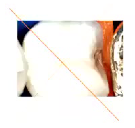
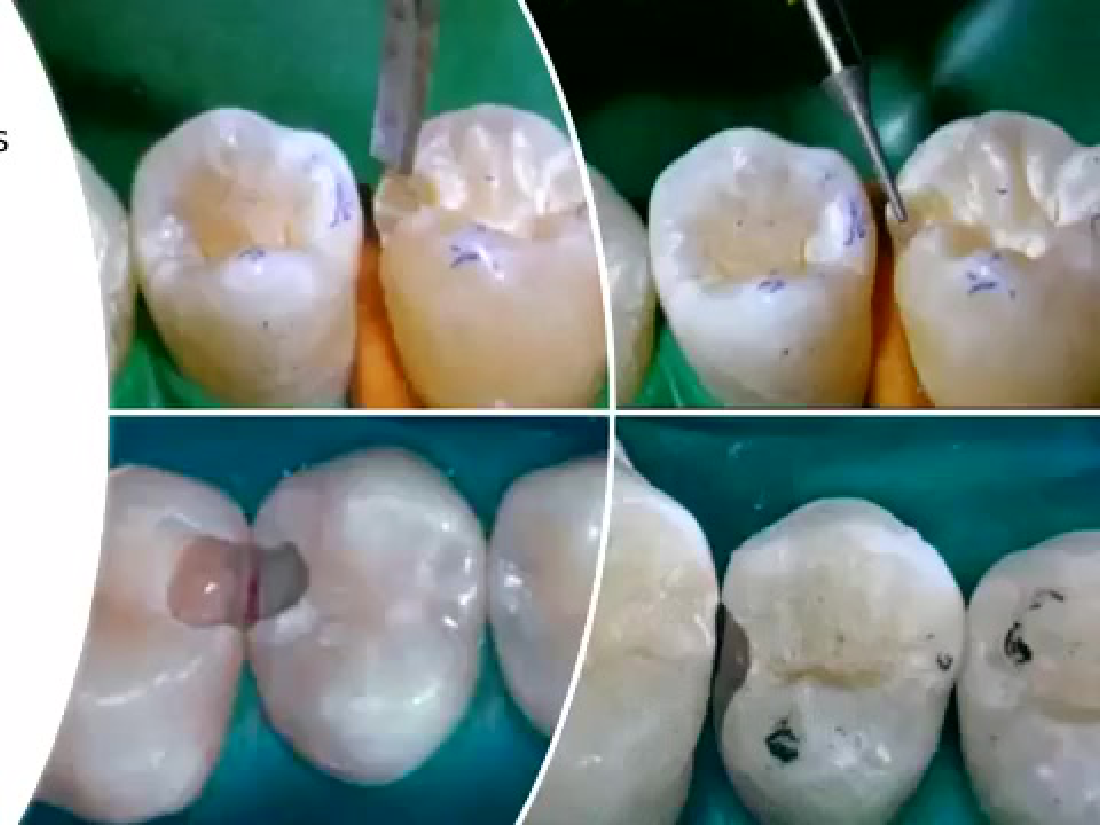
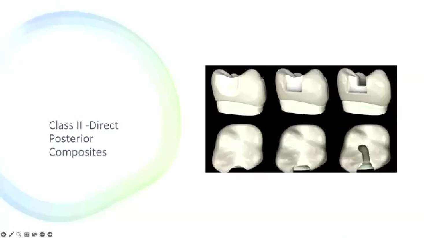
Dental models showing Class II direct posterior composite cavity preparations and filled restorations — Class II - Direct Posterior Composites
This is not Convenience Form?
 |  |
Preparation Depth and Width1314
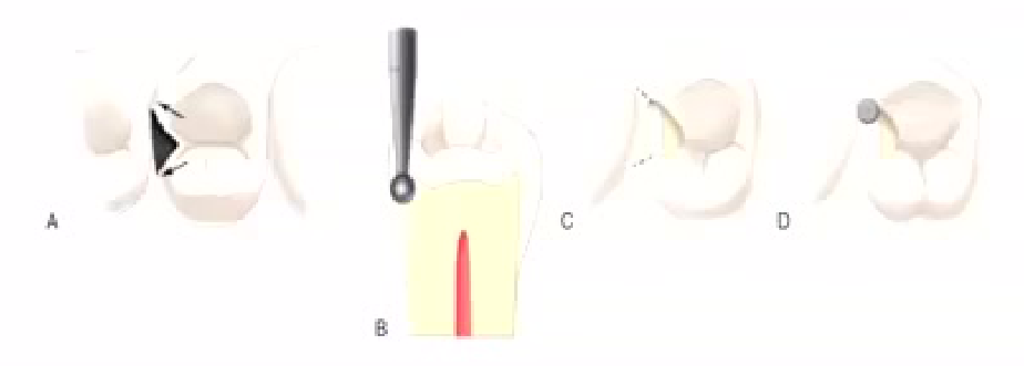
The pulpal floor is prepared with the instrument to a depth that is approximately 0.2 mm inside the DEJ. The instrument is moved to include caries and all defects facially or lingually or both, as it transverses the central groove. Every effort should be made, however, to keep the faciolingual width of the preparation as narrow as possible. The initial depth is maintained during the mesiodistal movement, but follows the rise and fall of the underlying DEJ.
Lecturer — Preparation Access
The preparation should remain as conservative as possible while still being clinically manageable.
- Remove unsupported enamel and provide enough access for composite placement, matrix placement, and finishing.
- Selective contact opening may be justified when the contact is too tight for matrix placement or finishing.
- The final preparation should allow the composite margin to be placed where it can be finished and cleaned.
 |  |  |
 |  |
Bevels
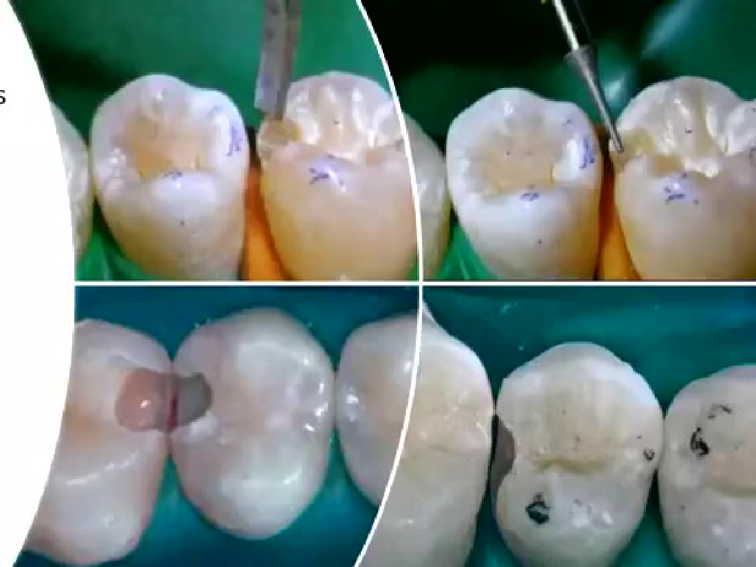
Bevel Placement Decisions151617
Should I bevel this margin?
-
Enamel? → Yes
-
Small occlusal? → Usually no
-
Visible proximal enamel? → Maybe
-
Root dentine? → No
-
A small enamel margin may be beveled when the bevel helps remove unsupported enamel.
-
Beveling is more appropriate in non-stress-bearing areas.
-
Proximal enamel should not automatically be beveled because its crystal structure may flare at the proximal wall, leaving little enamel available for bonding if removed.
-
In anterior teeth, facial beveling may help the transition between tooth and composite disappear.
-
A bevel should be avoided if it would create a composite thickness of less than 2 mm in a loaded area.
Evidence on Occlusal Bevels181920
Placement of occlusal bevels has demonstrated no benefit to the longevity of class 2 resin composite restorations.
Lecturer — Occlusal Bevel Effects
An occlusal bevel does not make a Class II posterior composite restoration last longer.
- It may create a thin composite edge that can chip and become stained.
- Although beveling may improve appearance in some situations, it is not a longevity-enhancing step for an occlusal Class II margin.
- Bevels
 |  |
 |  |
Pre Wedging212223242526
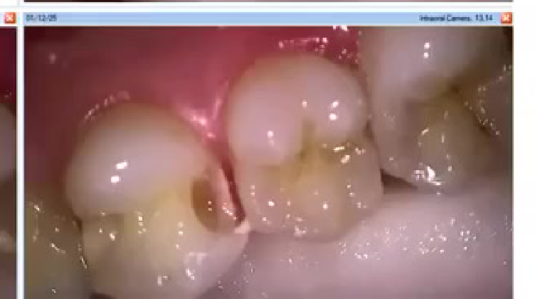
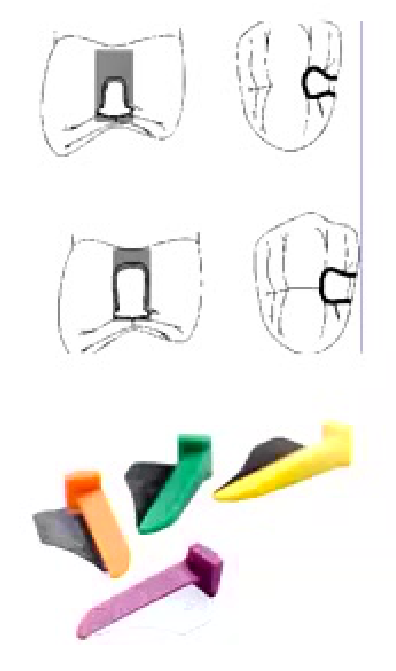
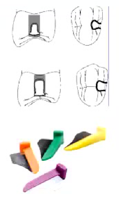
- Helps separate the teeth: easier to place matrix band – especially if preparing a slot technique or else if the caries is not extending beyond the contact.
- Some form of tooth separation, due to the PDL, such that after the restoration and the wedge is removed the tooth will return to its original position and lead to a tighter inter-proximal contact.
- Prevent damage to the adjacent tooth of restoration. E.g. using a fender wedge, wedge guard, etc.)
Placement of occlusal bevels has demonstrated no benefit to the longevity of class 2 resin composite restorations.
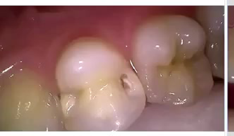
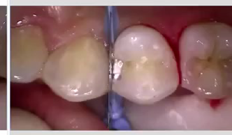
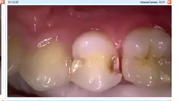
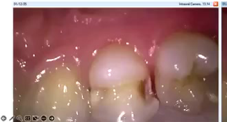
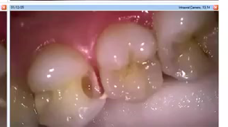
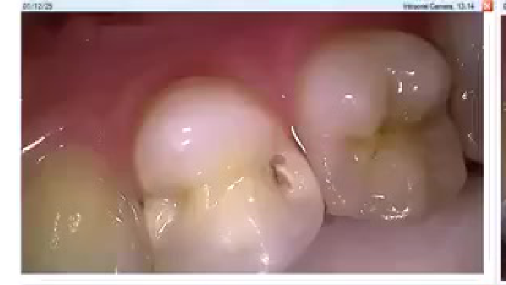
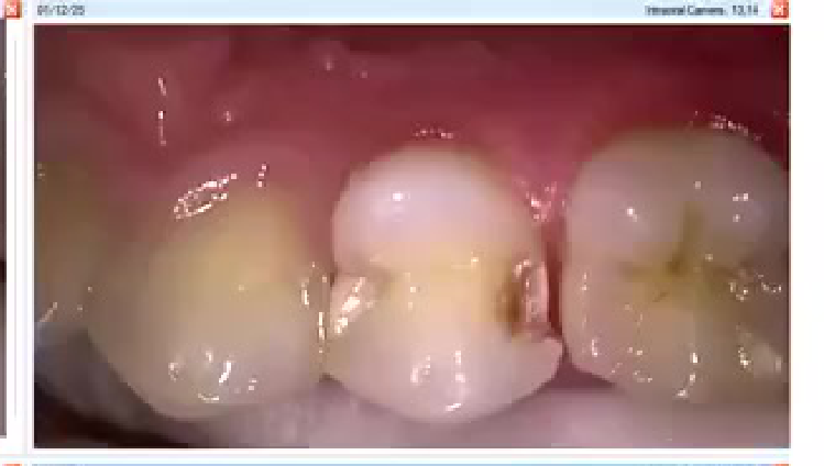
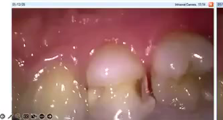
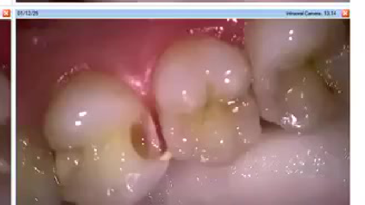
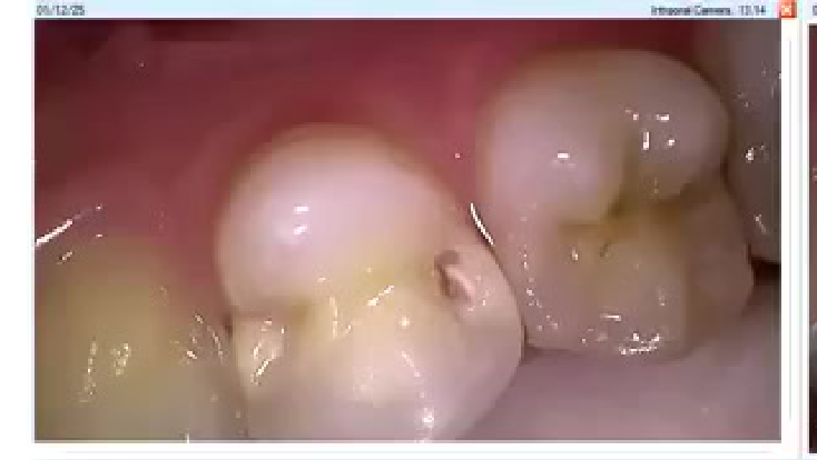
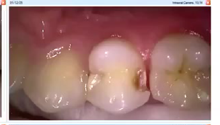
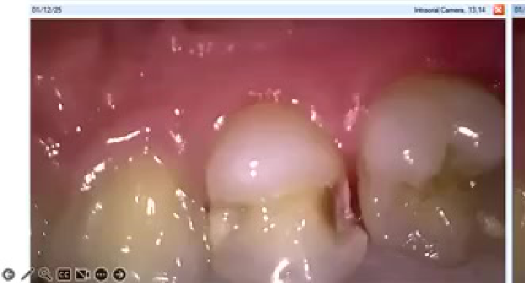
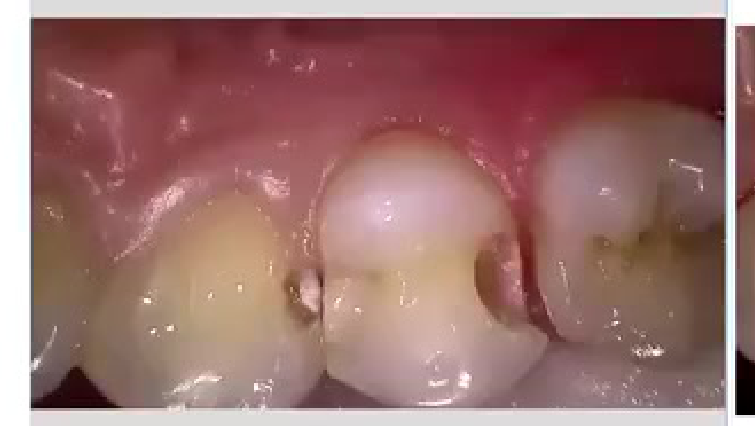
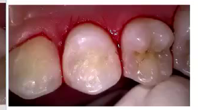
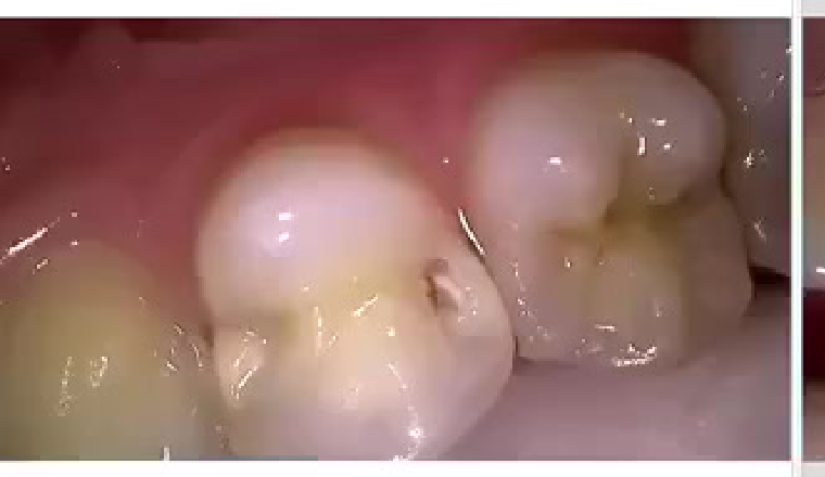
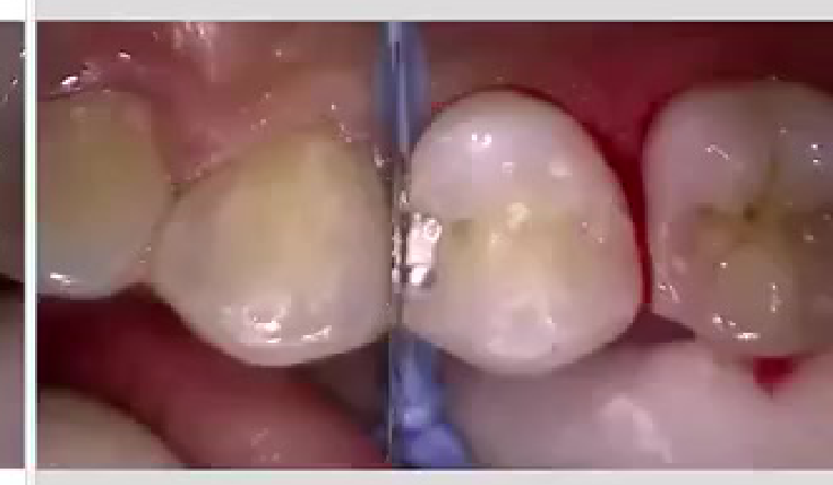
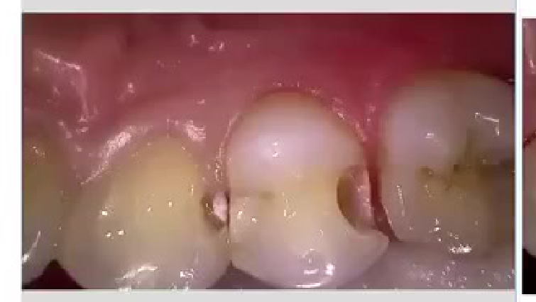
Clinical Case Images272829
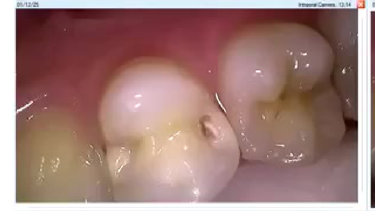
01/12/26 — Intraoral Camera, 13:14
01/12/26 — Intraoral Camera, 13
Composite image showing dental caries.
21/12/20 — Intraoral Camera, 13, 14
21/12/20 — Intraoral Camera, 13
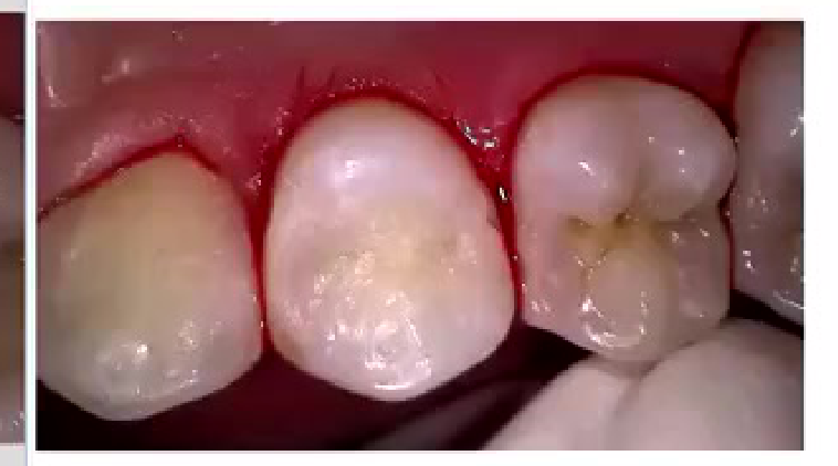
Matrix Systems
Every matrix must achieve:
The Matrix Checklist30
-
Gingival seal
-
Tight contact
-
Correct contour
-
Proper marginal ridge height
-
Verify the matrix band height against the adjacent marginal ridge.
-
Ensure the matrix is stable and not displaced buccally, lingually, or by the gingiva.
-
Expand the ring sufficiently before placement and recheck the matrix after wedging.
-
Confirm that the contact and marginal ridge are appropriately positioned and that the restoration can be finished and polished.
-
Use a periodontal probe to estimate the required matrix height; bands are available at approximately 3.5, 4.5, 5.5, and 6.5 mm.
Tofflemire Versus Sectional Matrix Systems3132
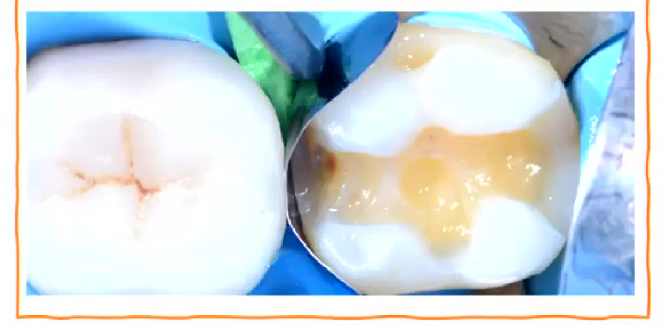 | 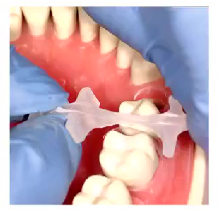 |
Tofflemire-style System33
- Fails to restore proximal anatomy
- Thin contact at the marginal ridge
- Large food trap below
- Increased likelihood of fracture, occlusal interference, recurrent caries, and periodontal disease
Lecturer — Tofflemire Indications
Tofflemire-style systems can still be useful when establishing broad overall contours or building extensive restorations.
- They may be used for large MOD-type defects or to create a preliminary composite form before converting it into a smaller MO or DO preparation.
- The lecturer described building the general form first, shaping it, cutting the smaller preparation, and then using a sectional matrix and ring for the final contact.
- An Automatrix avoids the large projecting portion of a conventional Tofflemire band but may still not reproduce the natural contour of a sectional matrix.
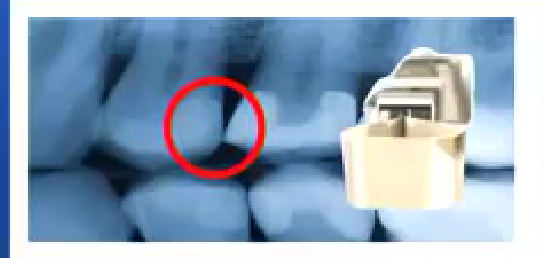 | 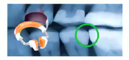 |
Composi-Tight® Sectional Matrix System
- Operator-friendly retaining system
- Naturally contoured bands
- Anatomically correct contacts
- Contacts at the height of contour
- Rings produce optimal tooth separation for excellent, tight contacts
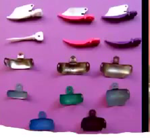
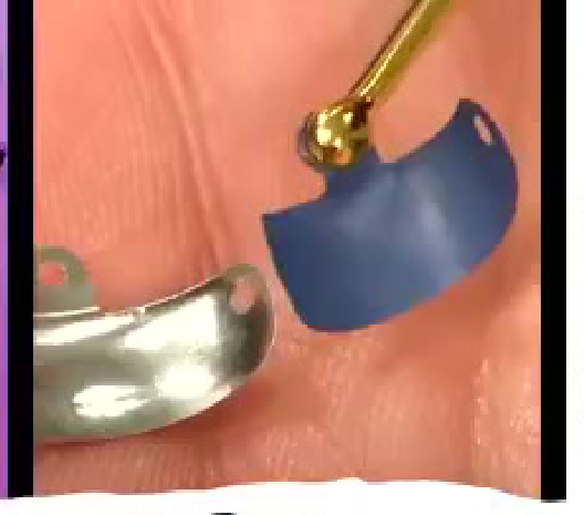
- Sectional matrices are available as metal, Teflon-coated, other pre-contoured, and clear matrices.
- Current evidence was described as showing no difference in clinical success based only on choosing a clear, metal, or mesh band.
- Separation rings provide approximately 60–80 or 70–90 microns of separation, depending on the system.
- Green rings were described for molars and yellow rings for premolars, with short and tall options available.
- If a ring snaps into place without sufficient expansion, the matrix may move or the ring may dislodge.
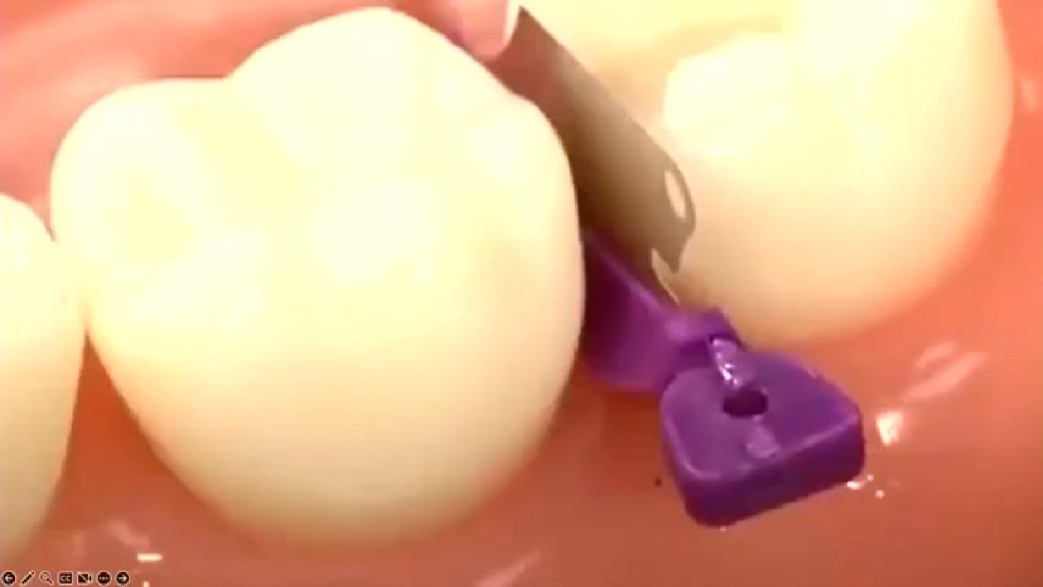
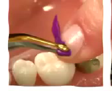
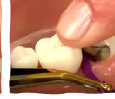
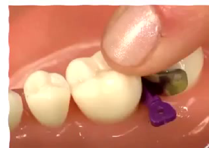
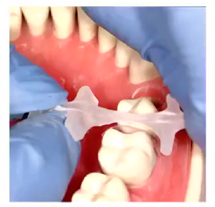
This particular wedge is called interproximator.
Wedge Placement Tips343536
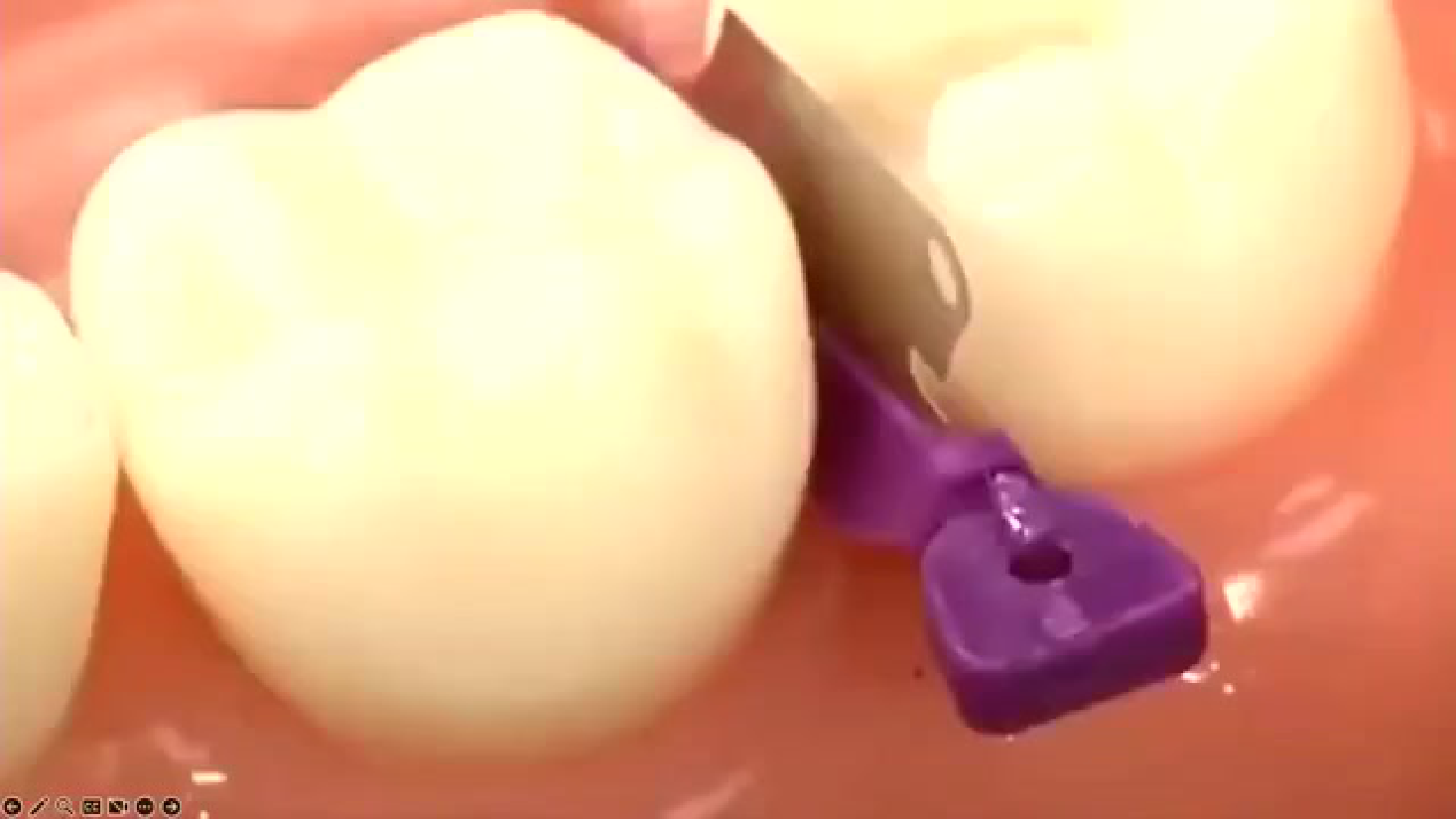
- Remember to hold the band down from the coronal aspect while placing the wedge. Can use your finger to hold it in place.
- You can use that finger which is holding the band down to rotate the wedge to place it from buccal or lingual.
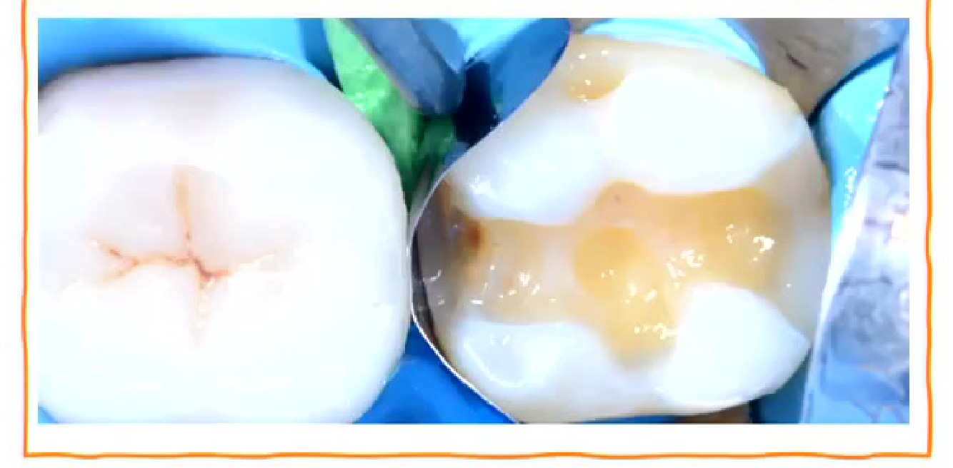
- Have a snug fit (no gap between proximal wall and the matrix). If gap is still present decide if large size wedge or double wedge or Teflon and wedge.
Lecturer — Wedge Adaptation
Wedge placement was described as critical for sealing the gingival margin, and the band should be checked again after wedging and before ring placement.
- Use a mirror to verify that gingival pressure has not displaced the band.
- A larger wedge may improve adaptation in a wide proximal space, but the wedge should not flatten the natural contour or interfere with the height of contour.
- If a gap remains, roll a small amount of Teflon into the gap and adapt it with a flat plastic instrument; slightly moistened Teflon or a suitable spray can prevent it from adhering to the instrument.
- Fender wedges or wedge guards may help protect the adjacent tooth during preparation.
Image replacement for wedge.
This particular wedge is called interproximator.
Double Wedging and Sectional Matrices37
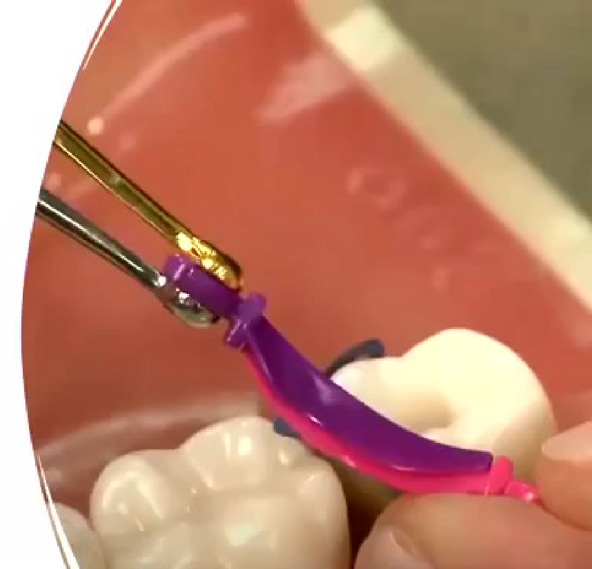
Double Wedging System38
Dental model demonstrating double wedging system with purple and pink wedges positioned between teeth.
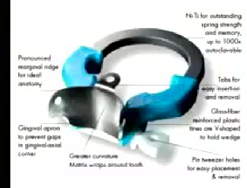
- Pronounced marginal ridge for ideal anatomy
- Ni-Ti for outstanding spring strength and memory, up to 1000x autoclavable
- Tabs for easy insertion and removal
- Glass-fiber reinforced plastic tines are V-shaped to hold wedge
- Gingival apron to prevent gaps in gingival-axial corner
- Greater curvature matrix wraps around tooth
- Pin tweezer holes for easy placement & removal
Lecturer — Double Wedging
Double wedging may be used when the gingival margin is very deep or subgingival.
- Place one wedge from each side; the wedges are designed to slide over one another and can improve adaptation at a deep gingival margin.
- The technique can be combined with Teflon when a gap remains.
- In a shallow preparation, wedges from both sides may flatten or distort the matrix, so they must not creep onto the height of contour.
Sectional Matrices39
- Metal sectional matrices: variety of pre-curved, subgingival, and coated or non-coated
Audio Appendix
Additional Audio Content
The following sections from the lecture audio did not correspond to any heading in the main document.
Flowable composites and proximal adaptation
Flowable composite was discussed as a liner for deep proximal boxes and internal line angles.
Potential purposes include:
- Improving adaptation in deep boxes.
- Filling irregularities and serrations.
- Acting as a flexible, stress-absorbing layer.
- Improving adaptation around internal line angles.
- Making small areas of flash easier to remove.
The flowable layer should remain thin.
- It should be adapted into the proximal box and internal areas.
- It should not be dragged up into a heavily loaded cusp area.
- A thicker flowable layer under a stress-bearing cusp may chip because of its lower strength.
- A flowable layer of less than approximately 1 mm was recommended.
- The clinician should avoid bringing flowable composite all the way to the cusp where it would become part of the main occlusal load.
The lecturer described a method of converting a complex restoration into a Class I restoration:
- Place a thin flowable layer.
- Adapt the restorative composite carefully against the matrix.
- Build the proximal wall.
- Establish the general occlusal form.
- Complete grooves and anatomy before finishing.
- Treat the remaining restoration as a simpler Class I composite.
A flat plastic instrument can be used to adapt the composite repeatedly against the matrix:
- Push the composite toward the wall.
- Compress it into place.
- Repeat from different directions.
- This reduces the likelihood of voids.
Anatomic grooves should be created during placement rather than during final finishing. Attempting to recreate anatomy only with finishing burs may flatten the anatomy and remove the desired grooves.
When to consider cusp coverage or an indirect restoration
The lecturer discussed several guidelines:
- If more than 3 mm of tooth structure through the central ridge has been destroyed, particularly in a premolar, cusp coverage should be considered.
- If marginal ridges and oblique ridges are gone, much of the tooth structure has been compromised.
- A practical rule of thirds was discussed: when more than two-thirds of the tooth is gone, the clinician should consider whether a filling material is appropriate.
- These are not absolute rules, and a composite cusp build-up may still be possible, but the success rate is lower.
- Cusp coverage should also be considered when:
- The cusp is undermined.
- The occlusal contact lies over the undermined area.
- Removing unsupported enamel would leave a margin partly on composite and partly on tooth.
- Less than approximately 2 mm of supporting tooth structure remains in a heavily loaded area.
The decision should not be driven only by the availability of a particular indirect system. The clinician should consider what the remaining tooth structure justifies.
Purposes of pre-wedging
- Separates the teeth by extending the periodontal ligament space.
- Creates more working room.
- Makes matrix placement easier.
- Helps protect the adjacent tooth.
- Can provide access when caries is located toward the buccal or lingual side.
- Allows the tooth to return to its original position after the wedge is removed, producing a tighter final contact.
A shaped wooden wedge may be used:
- Place it after topical anesthetic and during the anesthetic waiting period.
- Wooden wedges can absorb moisture and may advance further into the area.
- Pre-wedging can open the contact before the cavity is prepared.
- After removal, the periodontal ligament space returns and the contact becomes tighter.
Pre-wedging may complicate treatment when multiple adjacent restorations are being completed.
- If a distal restoration is pre-wedged before an adjacent mesial restoration, the later cavity may become more difficult to manage.
- In quadrant dentistry, treatment sequence should be planned.
- Completing one restoration, then another, and returning to the final restoration may provide better access and matrix control.
Preparation extent and contact opening
Preparation should be based on the extent and location of caries rather than on a predetermined amalgam-style shape.
- Earlier cavity designs were based on the principles of the G.V. Black amalgam preparation.
- The inverted, truncated shape associated with amalgam is not automatically appropriate for composite.
- Unsupported enamel should be removed.
- The preparation should provide:
- Access to remove caries.
- Sufficient space to place and pack the material.
- Access to clean and finish the matrix margins.
- A minimally invasive preparation should not become so small that the clinician cannot place, contour, finish, or clean the restoration.
Contact opening should be considered carefully:
- Opening the contact can improve finishing and cleansability.
- It can allow the composite margin to be placed on an accessible external surface.
- However, unnecessary extension may sacrifice sound enamel.
- The decision depends on where the caries is located and whether the margin can be finished and cleaned in the existing contact.
Finishing, polishing, and occlusal review
After the matrix is removed:
- Inspect for gingival flash.
- Remove flash with suitable instruments.
- A sharp scaler may be used carefully.
- Excessive pressure with a scaler may chip the composite.
- A blade may be used where permitted.
- Gingival flash should not be left because it can contribute to staining, breakdown, and leakage.
- Finish and polish the restoration.
- Recheck the occlusion against the preoperative occlusal record.
The final sequence summarized in the lecture was:
- Rubber dam.
- Conservative preparation.
- Pre-wedging.
- Careful matrix placement.
- Correct wedge and ring placement.
- Proximal wall construction.
- Incremental composite placement.
- Adequate curing.
- Finishing and polishing.
- Occlusal check before and after restoration.
Bonding, polymerization shrinkage, and curing
The lecturer discussed the C-factor and polymerization shrinkage.
Potential consequences of polymerization shrinkage include:
- Postoperative sensitivity.
- Recurrent caries.
- Cusp fracture.
- Stress at bonded surfaces.
The clinician should:
- Consider the number of bonded surfaces.
- Avoid unnecessarily large increments.
- Use an appropriate flowable layer where indicated.
- Place composite incrementally.
- Adapt each increment carefully.
- Cure each increment sufficiently.
Curing technique should include:
- Checking the curing light regularly.
- Knowing the light’s intensity and wavelength.
- Positioning the light close to the restoration.
- Moving the light slightly to address areas away from the center.
- Giving additional curing from different directions after matrix removal.
- Allowing longer curing when increments are thicker than the manufacturer’s specified thickness.
 |  |
 |
Clinical Cases
Case: Management of deep subgingival caries with severe bleeding
Question
Scenario: A student presents a clinical scenario of a molar (tooth 17) with deep subgingival caries (1-2mm) and severe gingival bleeding that prevents standard matrix band adaptation and isolation.
What’s shown: A verbal clinical scenario of a bleeding, deep subgingival proximal box on a molar.
Consider: How to achieve isolation, control bleeding, and place a matrix band for a successful restoration in this environment.
Answer
Observations:
- Subgingival caries compromises isolation and bonding (bonding to dentin/cementum is weaker and more prone to breakdown).
- Severe bleeding prevents proper matrix band adaptation.
Reasoning: If isolation is impossible, a temporary GIC restoration can be placed until the gingiva is healthy. If proceeding, use retraction cord with an astringent (e.g., haemodate) to control bleeding, followed by a medium-to-thick rubber dam to push the papilla away. Trim a V-ring matrix, use double wedging or Teflon to adapt the band subgingivally, and ensure the retraction cord remains in place during the procedure.
Takeaway: Controlling gingival bleeding and achieving isolation are critical for subgingival composite success; if impossible, defer to a temporary restoration or use advanced isolation techniques like a rubber dam with retraction cord.
Case: Evaluation of Class II cavity preparation designs
Question
Scenario: The lecturer shows three different Class II cavity preparations and asks the students to choose their preferred design.
What’s shown: Three images of Class II cavity preparations with varying extents of proximal box opening and enamel removal.
Consider: Which cavity preparation design is best and why.
Answer
Observations:
- The three preparations show different approaches to opening the contact and removing enamel.
- Some designs open the contact more extensively than others.
Reasoning: The choice of preparation design depends entirely on the extent and location of the caries, rather than a preconceived preference or strict GV Black principles. Opening the contact provides better access for finishing and matrix placement, but unnecessary destruction of good enamel should be avoided.
Takeaway: Cavity preparation design should be dictated by the actual extent and location of the caries, balancing the need for access and finishing with the preservation of healthy enamel.
Case: Decision-making for cusp capping in a molar
Question
Scenario: The lecturer presents a scenario of an MO cavity preparation on a molar where caries extends underneath the enamel, and asks when to decide to cap a cusp.
What’s shown: A scenario of a cavity preparation where caries extends under the enamel, with consideration of occlusal loading (blue articulating marks).
Consider: When to decide to cap a cusp during cavity preparation.
Answer
Observations:
- Caries extends underneath, undermining the enamel.
- Occlusal loading (blue marks) is present on the affected area.
Reasoning: If the remaining enamel is undermined and the occlusal load falls on the composite-tooth interface or a thin enamel margin, the cusp must be capped to prevent fracture. Checking occlusion before preparation helps map out the loading and identify undermined enamel.
Takeaway: The decision to cap a cusp depends on the extent of undermined enamel and the location of occlusal loading; always check occlusion before preparation to avoid finishing with a weak margin.
Case: Cavity preparation and matrix sequencing in a molar
Question
Scenario: The lecturer presents a clinical case from December showing a molar cavity preparation without a rubber dam, followed by a subsequent image showing the placement of a fender wedge and the sequence of quadrant dentistry.
What’s shown: Images of a molar cavity preparation with moisture issues, the use of a pre-placed wooden wedge, and the subsequent placement of a fender wedge and matrix system for adjacent teeth.
Consider: How to manage moisture, gain access, and sequence restorations in quadrant dentistry without a rubber dam.
Answer
Observations:
- Moisture contamination is present due to the lack of a rubber dam.
- A wooden wedge was pre-placed before preparation to extend the PDL space and open the contact.
- A fender wedge is used in the subsequent step to protect the adjacent tooth and adapt the matrix.
- The sequence involves restoring the canine before the premolar.
Reasoning: Pre-wedging helps control moisture and provides access for cleaning tight contacts. In quadrant dentistry, restoring the canine first prevents matrix bands and rings from interfering with each other in the smaller premolar space. A fender wedge protects the adjacent tooth and improves matrix adaptation.
Takeaway: Pre-wedging and proper sequencing (e.g., canine before premolar) are critical techniques for managing access, moisture, and matrix interference in quadrant dentistry, especially when a rubber dam is not used.
Case: Restoring a complex Class II cavity with a hybrid matrix technique
Question
Scenario: The lecturer presents a technique for restoring a large or complex Class II cavity where standard sectional matrices fail to provide the correct contour.
What’s shown: A technique demonstration of building up a tooth with a Tofflemeyer band, then cutting it into MO and DO slots to place sectional matrices.
Consider: How to achieve proper contour and contact in a complex or large Class II restoration.
Answer
Observations:
- Standard sectional matrices or Tofflemeyer bands alone struggle to provide the correct mid-coronal contour for large defects.
- The Tofflemeyer band provides the overall contour, while sectional matrices provide the proximal contact.
Reasoning: Building the entire contour with a Tofflemeyer band first, then cutting it into MO and DO segments, allows for the placement of sectional matrices (V-rings) to recreate the proper proximal contacts and contours without the bulk of the Tofflemeyer band interfering.
Takeaway: For complex Class II restorations, a hybrid matrix technique (building with a Tofflemeyer, then segmenting for sectional matrices) can predictably restore both overall contour and tight proximal contacts.
Case: Identifying voids in a flowable composite liner
Question
Scenario: The lecturer shows an image of a restoration with a flowable composite liner, highlighting areas where the matrix band was not properly adapted.
What’s shown: An image of a proximal box restoration showing a flowable composite liner with visible voids and improper band adaptation.
Consider: What critical errors are visible in the adaptation of the flowable composite and matrix band.
Answer
Observations:
- The matrix band was not properly adapted, resulting in a flat surface and voids in the flowable composite.
- The flowable composite adapted well in some areas but failed in others due to the band’s poor fit.
Reasoning: Even if the flowable composite flows well, a poorly adapted matrix band will leave voids and open margins at the gingival floor. These voids lead to leakage, staining, and breakdown. Proper band adaptation and careful removal of flash are essential.
Takeaway: A flowable composite liner cannot compensate for a poorly adapted matrix band; ensuring tight band adaptation is critical to avoid voids and marginal leakage.
Footnotes
-
Original PDF page 3: [[L2 Class II composites [good][extended]_slides.pdf#page=3|L2 Class II composites [good][extended] slides, p.3]] ↩
-
Original PDF page 1: [[L2 Class II composites [good][extended]_slides.pdf#page=1|L2 Class II composites [good][extended] slides, p.1]] ↩
-
Original PDF page 2: [[L2 Class II composites [good][extended]_slides.pdf#page=2|L2 Class II composites [good][extended] slides, p.2]] ↩
-
Original PDF page 4: [[L2 Class II composites [good][extended]_slides.pdf#page=4|L2 Class II composites [good][extended] slides, p.4]] ↩
-
Original PDF page 5: [[L2 Class II composites [good][extended]_slides.pdf#page=5|L2 Class II composites [good][extended] slides, p.5]] ↩
-
Original PDF page 6: [[L2 Class II composites [good][extended]_slides.pdf#page=6|L2 Class II composites [good][extended] slides, p.6]] ↩
-
Original PDF page 7: [[L2 Class II composites [good][extended]_slides.pdf#page=7|L2 Class II composites [good][extended] slides, p.7]] ↩
-
Original PDF page 9: [[L2 Class II composites [good][extended]_slides.pdf#page=9|L2 Class II composites [good][extended] slides, p.9]] ↩
-
Original PDF page 10: [[L2 Class II composites [good][extended]_slides.pdf#page=10|L2 Class II composites [good][extended] slides, p.10]] ↩
-
Original PDF page 8: [[L2 Class II composites [good][extended]_slides.pdf#page=8|L2 Class II composites [good][extended] slides, p.8]] ↩
-
Original PDF page 11: [[L2 Class II composites [good][extended]_slides.pdf#page=11|L2 Class II composites [good][extended] slides, p.11]] ↩
-
Original PDF page 12: [[L2 Class II composites [good][extended]_slides.pdf#page=12|L2 Class II composites [good][extended] slides, p.12]] ↩
-
Original PDF page 13: [[L2 Class II composites [good][extended]_slides.pdf#page=13|L2 Class II composites [good][extended] slides, p.13]] ↩
-
Original PDF page 14: [[L2 Class II composites [good][extended]_slides.pdf#page=14|L2 Class II composites [good][extended] slides, p.14]] ↩
-
Original PDF page 15: [[L2 Class II composites [good][extended]_slides.pdf#page=15|L2 Class II composites [good][extended] slides, p.15]] ↩
-
Original PDF page 16: [[L2 Class II composites [good][extended]_slides.pdf#page=16|L2 Class II composites [good][extended] slides, p.16]] ↩
-
Original PDF page 17: [[L2 Class II composites [good][extended]_slides.pdf#page=17|L2 Class II composites [good][extended] slides, p.17]] ↩
-
Original PDF page 18: [[L2 Class II composites [good][extended]_slides.pdf#page=18|L2 Class II composites [good][extended] slides, p.18]] ↩
-
Original PDF page 20: [[L2 Class II composites [good][extended]_slides.pdf#page=20|L2 Class II composites [good][extended] slides, p.20]] ↩
-
Original PDF page 21: [[L2 Class II composites [good][extended]_slides.pdf#page=21|L2 Class II composites [good][extended] slides, p.21]] ↩
-
Original PDF page 19: [[L2 Class II composites [good][extended]_slides.pdf#page=19|L2 Class II composites [good][extended] slides, p.19]] ↩
-
Original PDF page 22: [[L2 Class II composites [good][extended]_slides.pdf#page=22|L2 Class II composites [good][extended] slides, p.22]] ↩
-
Original PDF page 23: [[L2 Class II composites [good][extended]_slides.pdf#page=23|L2 Class II composites [good][extended] slides, p.23]] ↩
-
Original PDF page 24: [[L2 Class II composites [good][extended]_slides.pdf#page=24|L2 Class II composites [good][extended] slides, p.24]] ↩
-
Original PDF page 25: [[L2 Class II composites [good][extended]_slides.pdf#page=25|L2 Class II composites [good][extended] slides, p.25]] ↩
-
Original PDF page 26: [[L2 Class II composites [good][extended]_slides.pdf#page=26|L2 Class II composites [good][extended] slides, p.26]] ↩
-
Original PDF page 27: [[L2 Class II composites [good][extended]_slides.pdf#page=27|L2 Class II composites [good][extended] slides, p.27]] ↩
-
Original PDF page 28: [[L2 Class II composites [good][extended]_slides.pdf#page=28|L2 Class II composites [good][extended] slides, p.28]] ↩
-
Original PDF page 29: [[L2 Class II composites [good][extended]_slides.pdf#page=29|L2 Class II composites [good][extended] slides, p.29]] ↩
-
Original PDF page 30: [[L2 Class II composites [good][extended]_slides.pdf#page=30|L2 Class II composites [good][extended] slides, p.30]] ↩
-
Original PDF page 32: [[L2 Class II composites [good][extended]_slides.pdf#page=32|L2 Class II composites [good][extended] slides, p.32]] ↩
-
Original PDF page 33: [[L2 Class II composites [good][extended]_slides.pdf#page=33|L2 Class II composites [good][extended] slides, p.33]] ↩
-
Original PDF page 31: [[L2 Class II composites [good][extended]_slides.pdf#page=31|L2 Class II composites [good][extended] slides, p.31]] ↩
-
Original PDF page 34: [[L2 Class II composites [good][extended]_slides.pdf#page=34|L2 Class II composites [good][extended] slides, p.34]] ↩
-
Original PDF page 35: [[L2 Class II composites [good][extended]_slides.pdf#page=35|L2 Class II composites [good][extended] slides, p.35]] ↩
-
Original PDF page 36: [[L2 Class II composites [good][extended]_slides.pdf#page=36|L2 Class II composites [good][extended] slides, p.36]] ↩
-
Original PDF page 39: [[L2 Class II composites [good][extended]_slides.pdf#page=39|L2 Class II composites [good][extended] slides, p.39]] ↩
-
Original PDF page 37: [[L2 Class II composites [good][extended]_slides.pdf#page=37|L2 Class II composites [good][extended] slides, p.37]] ↩
-
Original PDF page 38: [[L2 Class II composites [good][extended]_slides.pdf#page=38|L2 Class II composites [good][extended] slides, p.38]] ↩