Clinical Workflow For Removable Partial Denture1
DR. AHMAD HENDAWI
DR. SHERYL TEO
Key Clinical Questions2
-
Acrylic or Co-Cr?
-
Which impression material?
-
Is this impression good enough?
-
How do I prevent my impression from getting stuck?
-
Do I border mould?
-
Do I need an MMR?
-
Do I need a secondary impression?
-
How do I assess the framework?
-
Whether a tooth try-in is needed before processing.
-
How to identify the first contact when inserting a denture and adjust conservatively.
-
The workflow should begin with the patient’s overall condition and treatment needs, rather than with the edentulous classification alone.

Diagnosis and Treatment Planning
Acrylic vs Co-Cr Decision Making3
Acrylic vs Co-Cr?
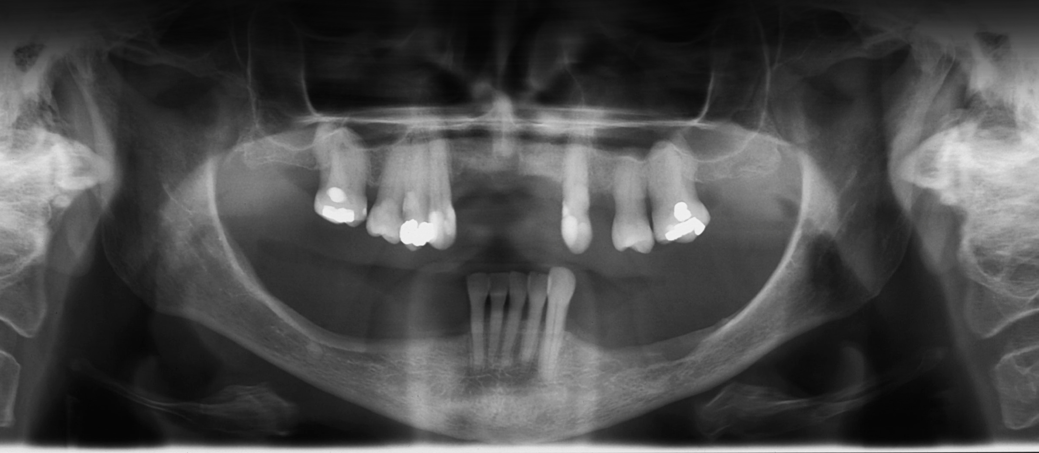
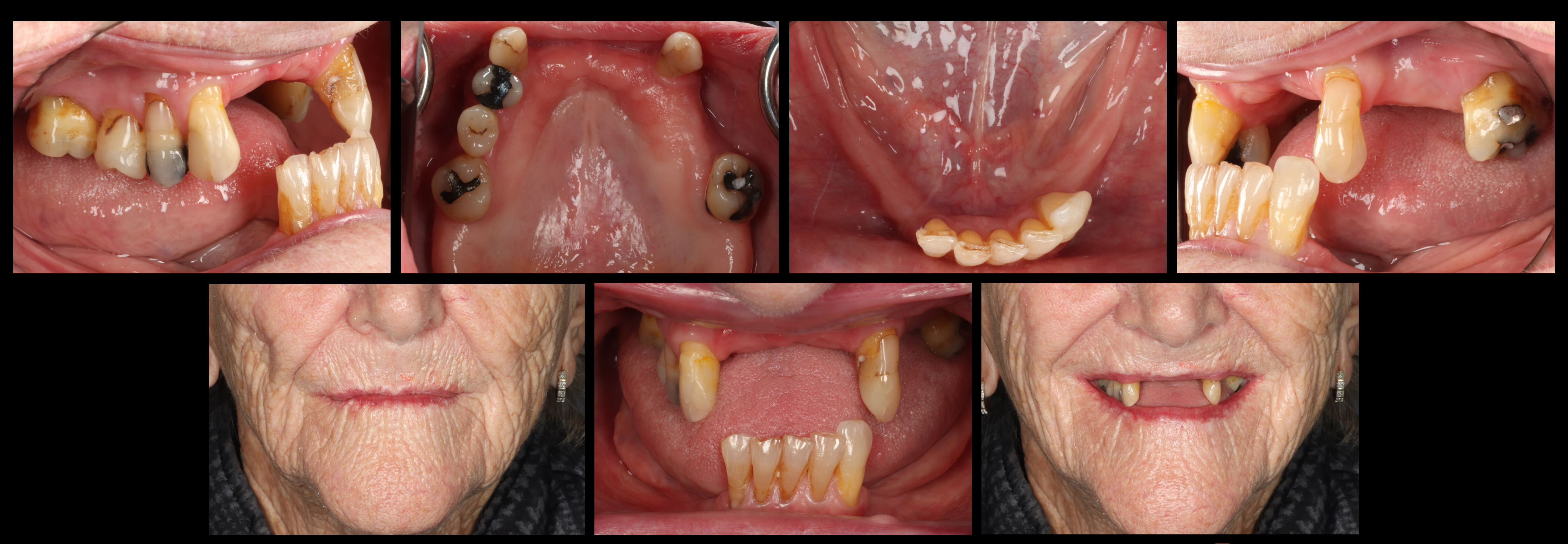
Examination and Assessment456
Diagnose before you design
- “What denture should I make?”
- “What is happening in this mouth?”
Examination
Periodontal, restorative, occlusal, anatomical, functional, patient-related factors
 | 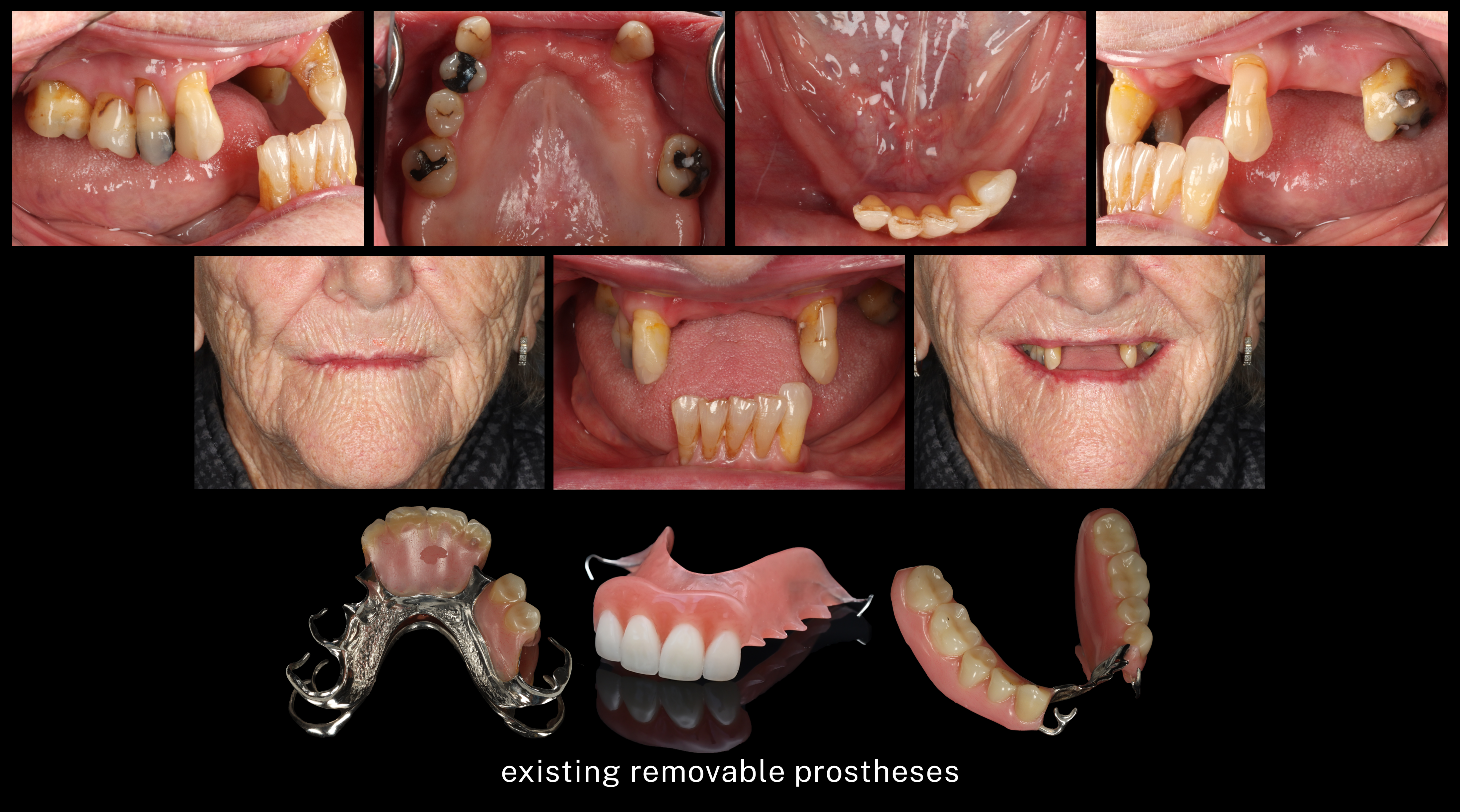 |
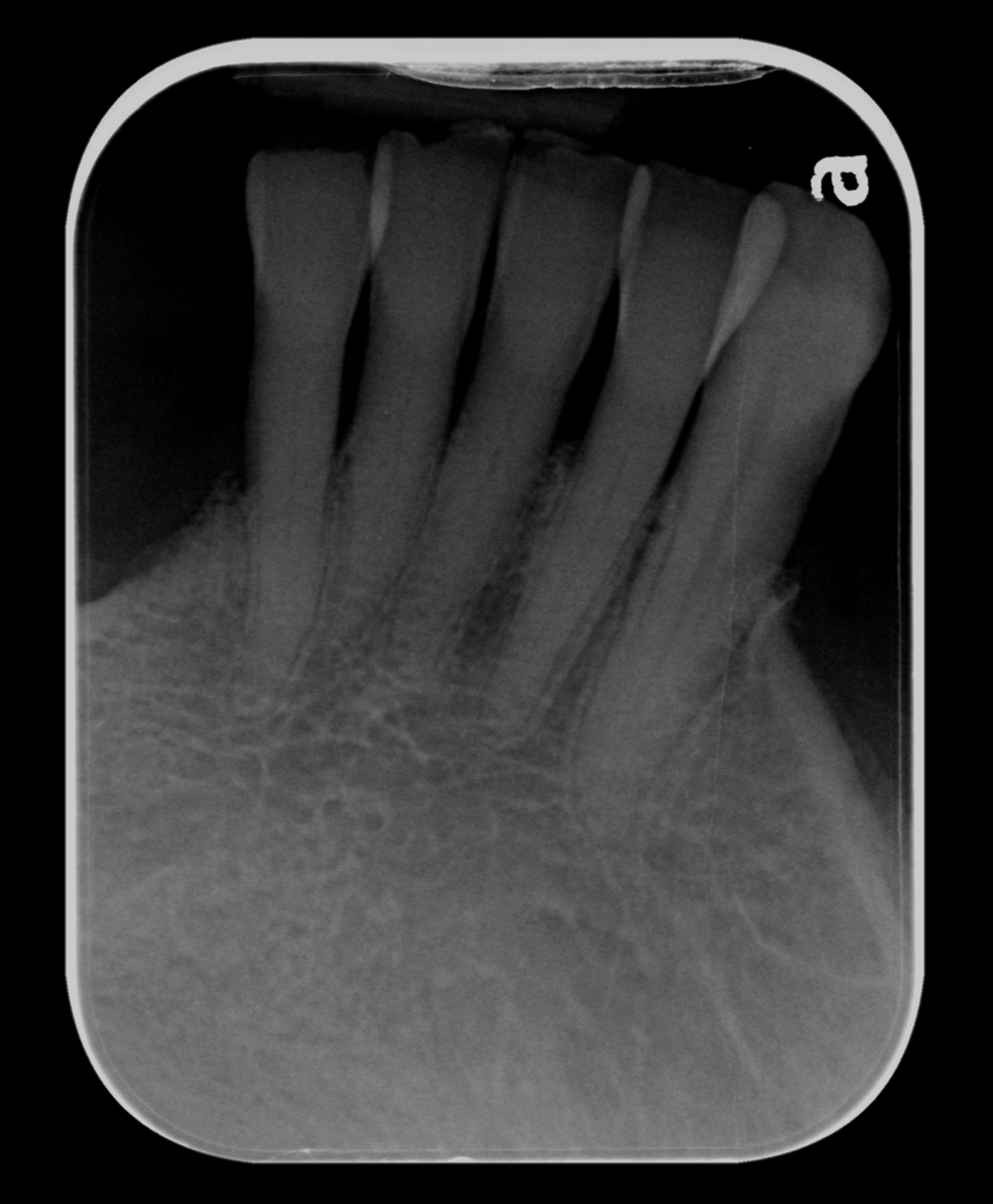
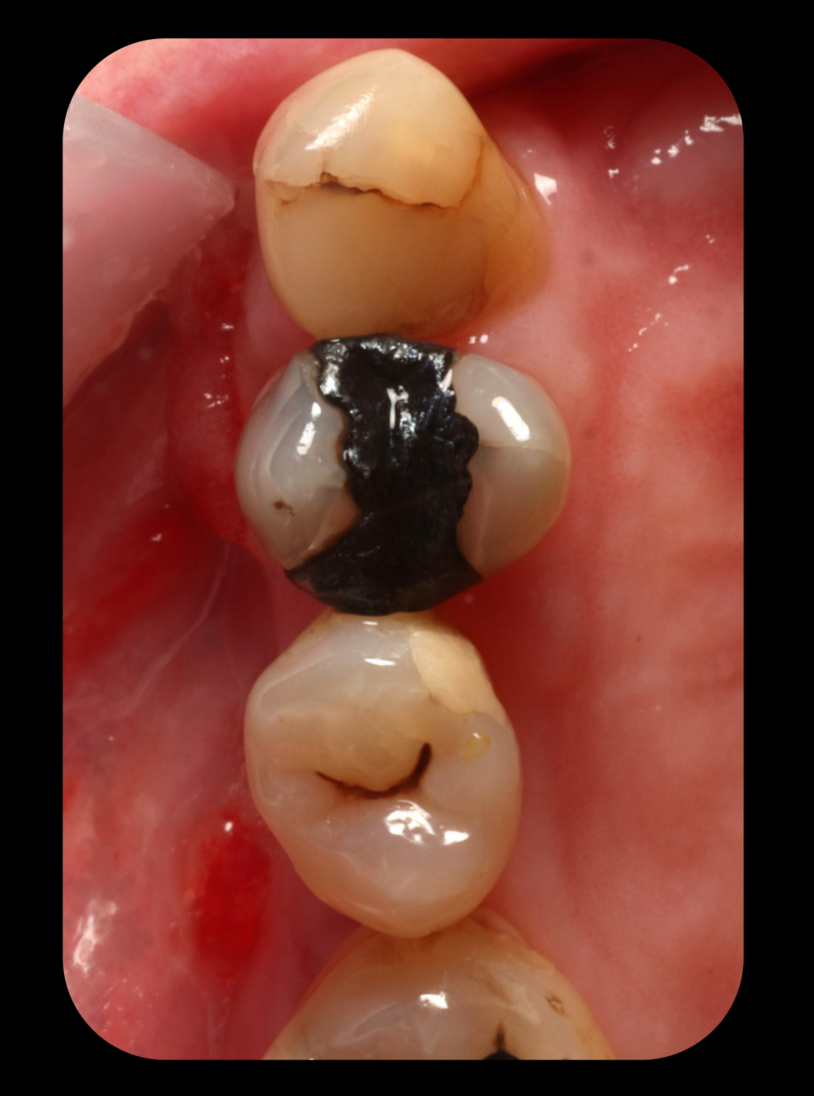
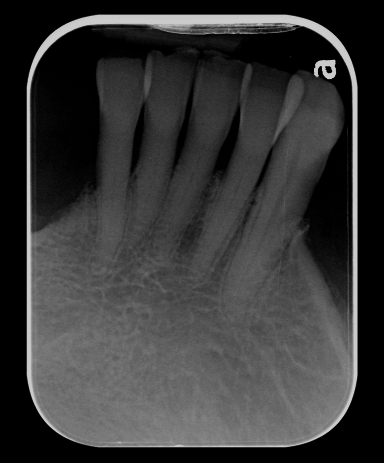
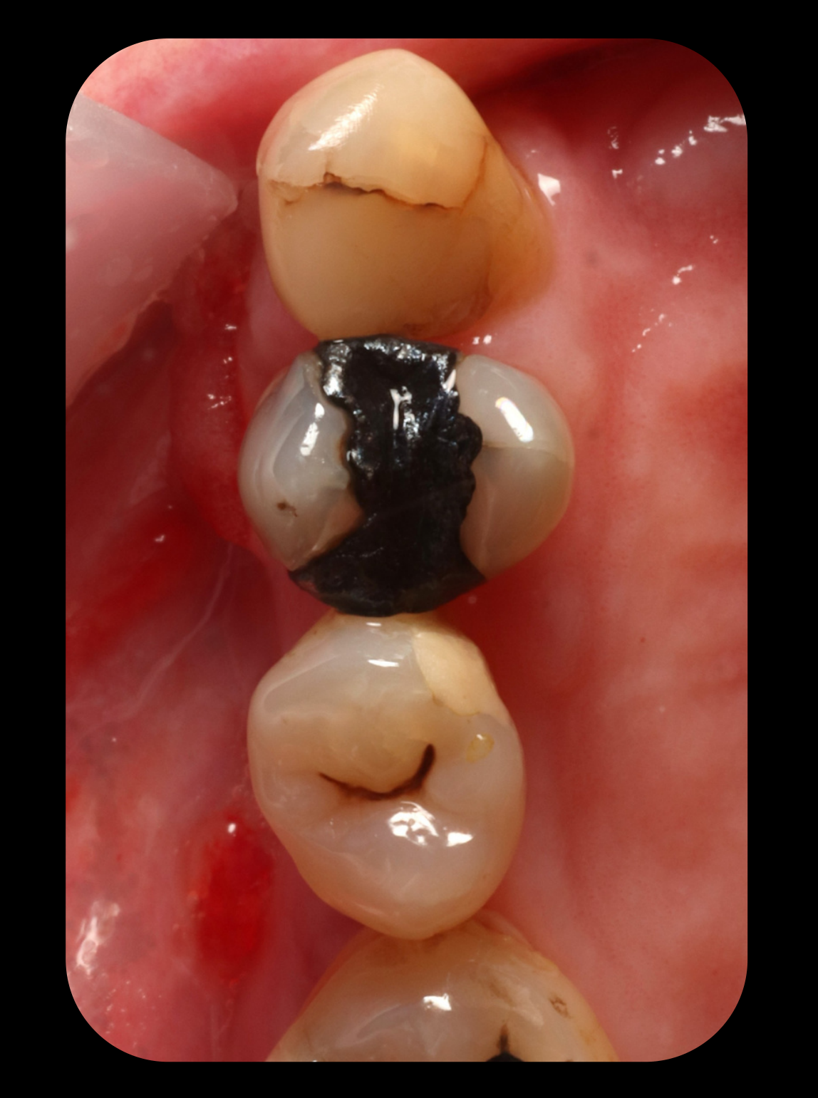
Can This Tooth Contribute78
What is the individual and overall *prognosis?
- Periodontal support
- Mobility
- Caries / restorability
- Crown & root anatomy
- Strategic position
- Cleansability
Lecturer — Tooth Contribution
A tooth should not be judged simply as good or bad; its value depends on the planned denture and overall rehabilitation.
- A restorable tooth with a good prognosis may still be extracted if it does not fit the treatment plan.
- A questionable tooth may be retained when it is a terminal abutment or otherwise crucial to the prosthesis.
 |  |
 |  |
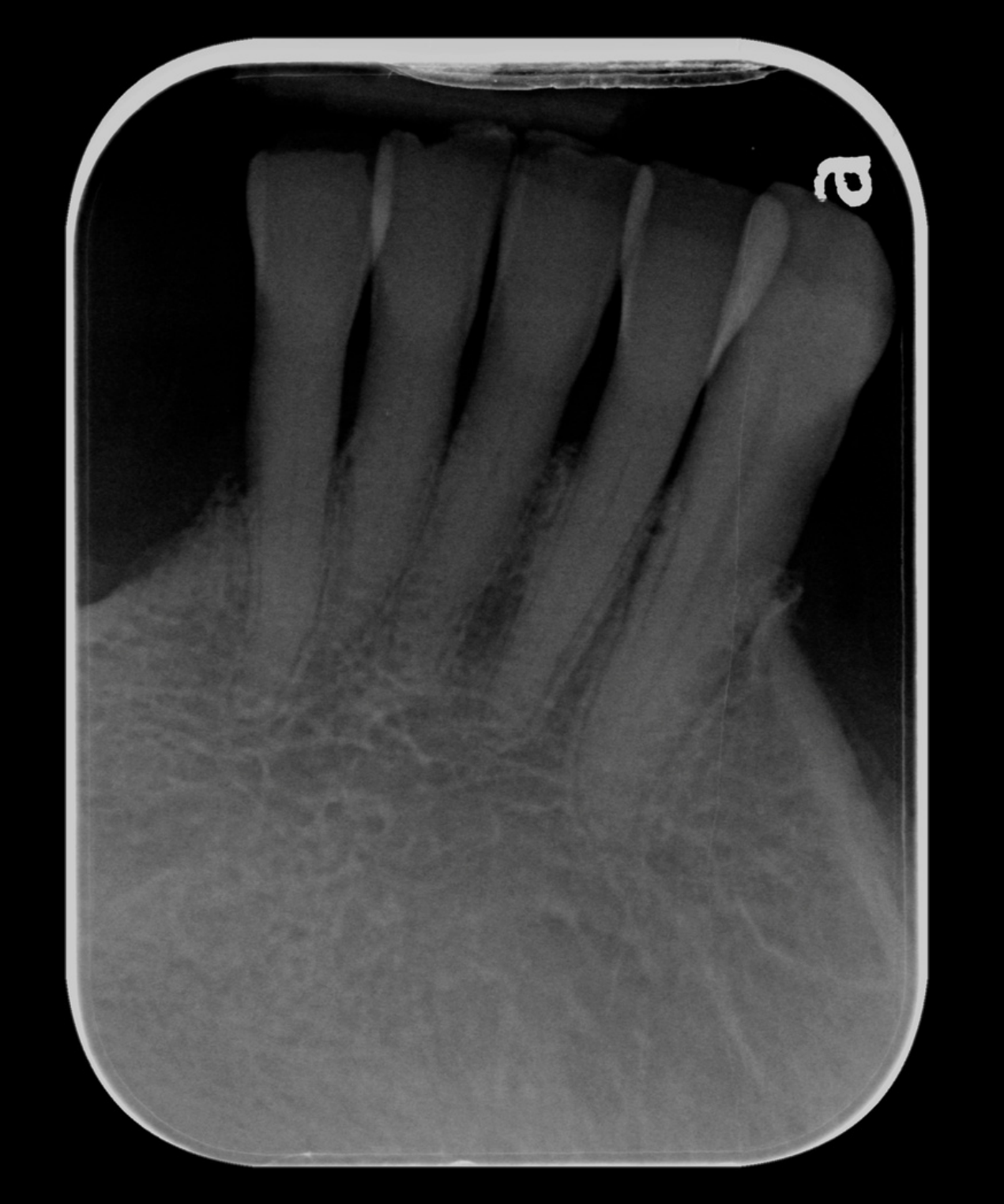
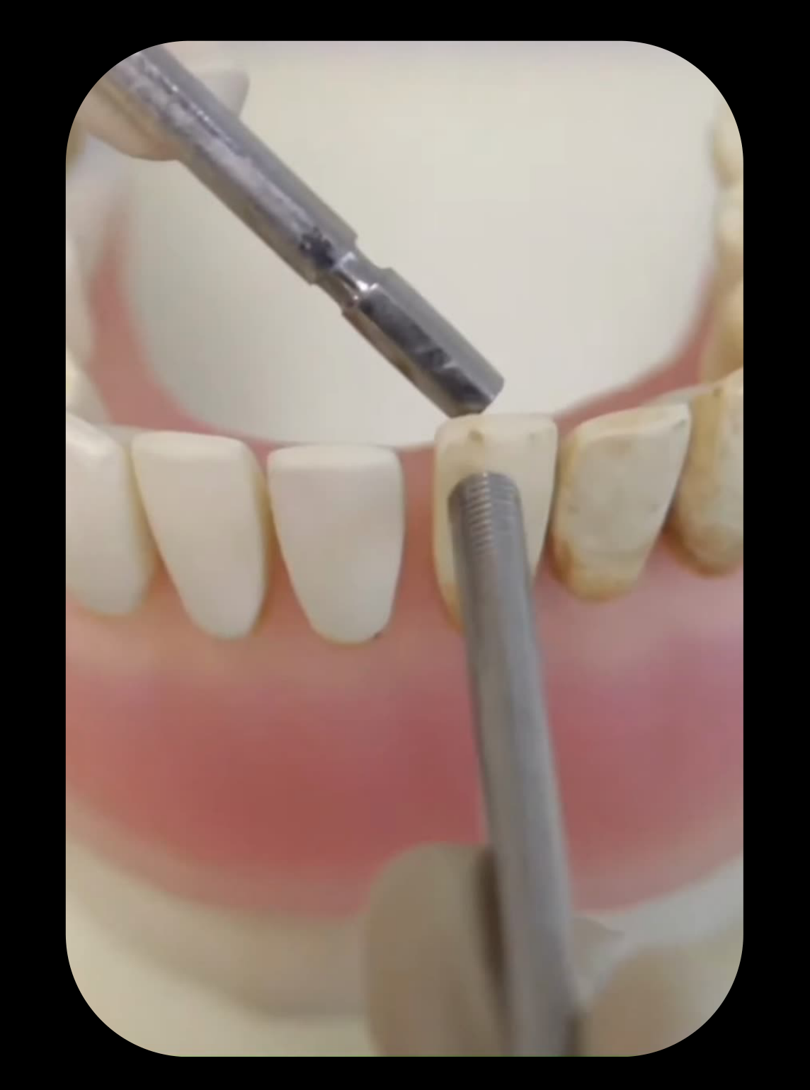
Mobility as a Clinical Finding9
Mobility is a finding, not a prognosis!
Why is it mobile?
- Periodontal disease
- Trauma from occlusion
- Periapical infection
- Traumatic injury
- Pathologic jaw lesion
Is the cause controlled?
Lecturer — Mobility and Material Choice
Mobility itself is not a disease, so its cause should be identified and treated before deciding whether the tooth can contribute.
- When mobility is caused by trauma from occlusion, manage the occlusal trauma first and then assess the tooth’s response.
- A mobile tooth should not automatically be extracted; if mobility improves or does not progress, it may remain suitable for the denture.
- Mobility alone does not determine whether acrylic or cobalt-chromium is selected.
 |  |
Periodontitis Staging and Grading10
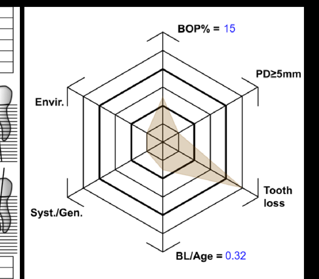
Periodontitis: stage, grade and current status
- BOP% = 15
- PD ≥ 5 mm
- Tooth loss
- BL/Age = 0.32
- Envir.
- Syst./Gen.
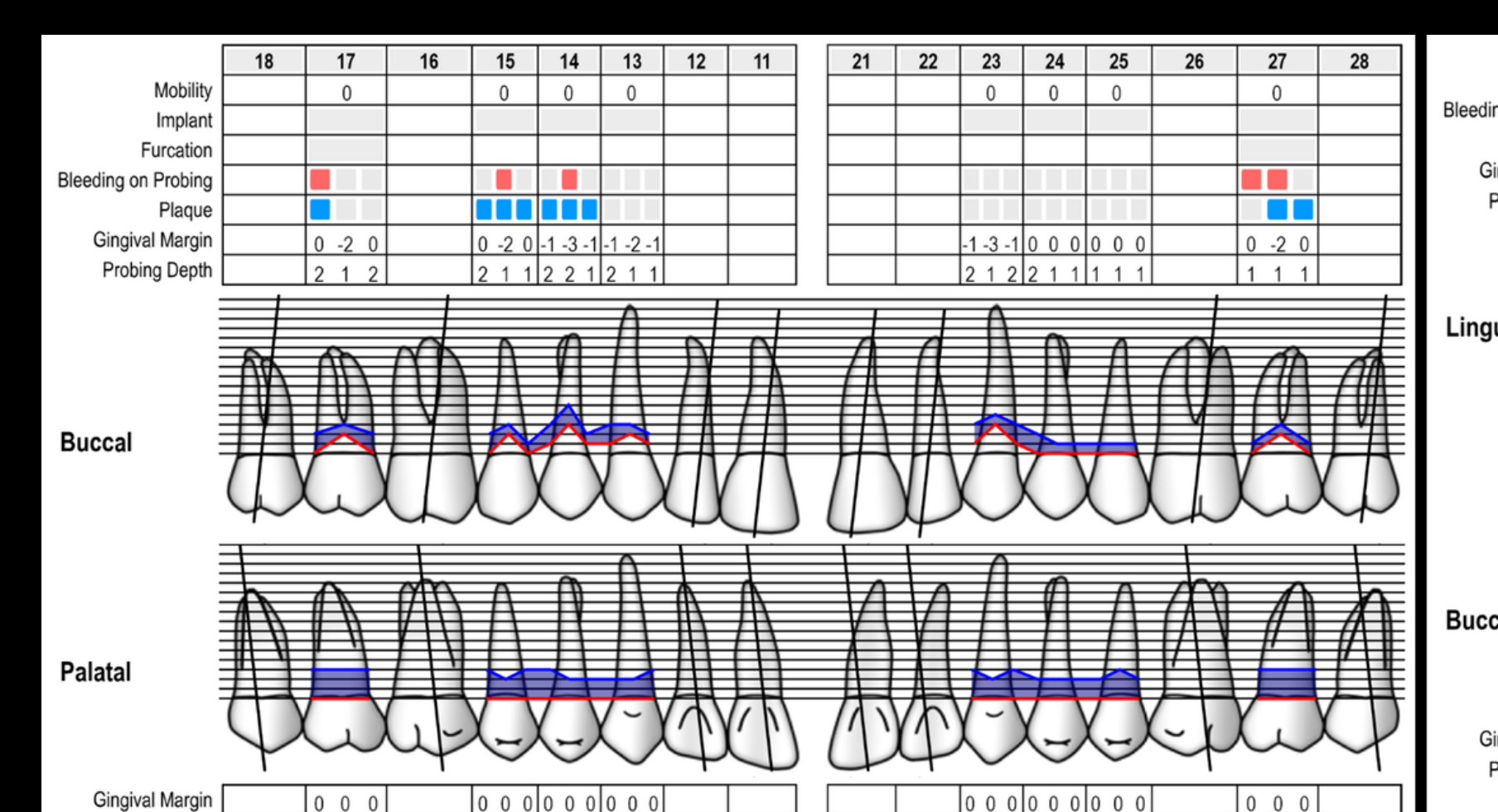
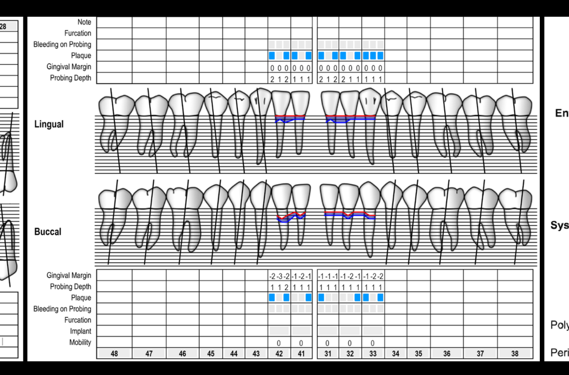
Polygon surface: 16.45448 Periodontal Risk: medium
(Dental chart with rows for Mobility, Implant, Furcation, Bleeding on Probing, Plaque, Gingival Margin, and Probing Depth across teeth 18–28 and 48–38, shown buccal and lingual, with measurements indicated by blue and red squares.)
Periodontitis: stage, grade and current status
Periodontitis: Staging
Staging intends to classify the severity and extent of a patient’s disease based on the measurable amount of destroyed and/or damaged tissue as a result of periodontitis and to assess the specific factors that may attribute to the complexity of long-term case management.
Initial stage should be determined using clinical attachment loss (CAL). If CAL is not available, radiographic bone loss (RBL) should be used. Tooth loss due to periodontitis may modify stage definition. One or more complexity factors may shift the stage to a higher level. See perio.org/2017wwdc for additional information.
| Stage I | Stage II | Stage III | Stage IV | ||
|---|---|---|---|---|---|
| Severity | Interdental CAL (at site of greatest loss) | 1 – 2 mm | 3 – 4 mm | ≥5 mm | ≥5 mm |
| RBL | Coronal third (<15%) | Coronal third (15% – 33%) | Extending to middle third of root and beyond | Extending to middle third of root and beyond | |
| Tooth loss (due to periodontitis) | No tooth loss | ≤4 teeth | ≥5 teeth | ||
| Complexity | Local | • Max. probing depth ≤4 mm • Mostly horizontal bone loss | • Max. probing depth ≤5 mm • Mostly horizontal bone loss | In addition to Stage II complexity: • Probing depths ≥6 mm • Vertical bone loss ≥3 mm • Furcation involvement Class II or III • Moderate ridge defects | In addition to Stage III complexity: • Need for complex rehabilitation due to: – Masticatory dysfunction – Secondary occlusal trauma (tooth mobility degree ≥2) – Severe ridge defects – Bite collapse, drifting, flaring – < 20 remaining teeth (10 opposing pairs) |
| Extent and distribution | Add to stage as descriptor | For each stage, describe extent as: • Localized (<30% of teeth involved); • Generalized; or • Molar/incisor pattern |
Periodontitis: Grading
Grading aims to indicate the rate of periodontitis progression, responsiveness to standard therapy, and potential impact on systemic health.
Clinicians should initially assume grade B disease and seek specific evidence to shift to grade A or C.
See perio.org/2017wwdc for additional information.
| Grade A: Slow rate | Grade B: Moderate rate | Grade C: Rapid rate | |||
|---|---|---|---|---|---|
| Primary criteria | Direct evidence of progression | Radiographic bone loss or CAL | No loss over 5 years | <2 mm over 5 years | ≥2 mm over 5 years |
| Indirect evidence of progression | % bone loss / age | <0.25 | 0.25 to 1.0 | >1.0 | |
| Case phenotype | Heavy biofilm deposits with low levels of destruction | Destruction commensurate with biofilm deposits | Destruction exceeds expectations given biofilm deposits; specific clinical patterns suggestive of periods of rapid progression and/or early onset disease | ||
| Grade modificators | Risk factors | Smoking | Non-smoker | <10 cigarettes/day | ≥10 cigarettes/day |
| Diabetes | Normoglycemic / no diagnosis of diabetes | HbA1c <7.0% in patients with diabetes | HbA1c ≥7.0% in patients with diabetes |
Periodontitis: stage, grade and current status
Stage
- Staging intends to classify the severity and extent of a patient’s disease based on the measurable amount of destroyed and/or damaged tissue of periodontitis and to assess the specific factors that may attribute to the complexity of long-term case management.
- Initial stage should be determined using clinical attachment loss (CAL). If CAL is not available, radiographic bone loss (RBL) should be used. Tooth loss due to periodontitis may modify stage definition. One or more complexity factors may shift the stage to a higher level.
 |  |
 |
Periodontitis Staging Table
| Periodontitis | Stage I | Stage II | Stage III | Stage IV |
|---|---|---|---|---|
| Severity — Interdental CAL (at site of greatest loss) | 1 – 2 mm | 3 – 4 mm | ≥5 mm | ≥5 mm |
| RBL | Coronal third (<15%) | Coronal third (15% – 35%) | Extending to middle third of root and beyond | Extending to middle third bone destruction |
| Tooth loss (due to periodontitis) | No tooth loss | |||
| Complexity — Local | • Max. probing depth <4 mm • Mostly horizontal bone loss | Not applicable (radiographic bone loss <25–30%) | In addition to Stage II: • Vertical bone loss • Class II or III • Complex ridge defects | In addition to Stage III: • Tooth loss (>4 remaining teeth not deployable) • Severe ridge defects • Bite collapse • < 20 remaining (10 opposing) |
| Extent and distribution | • Localized (<30% of teeth involved); • Generalized; or • Molar/incisor pattern |
How severe? How complex? How much destruction?
Grade + Today
- Grading intends to categorize the rate of periodontitis progression, responsiveness to standard therapy, and potential impact on systemic health.
- Initially assume grade B disease and seek specific evidence to shift to grade A or C.
Periodontitis Grading Table
| Periodontitis Grading | Grade A: Slow rate | Grade B: Moderate rate | Grade C: Rapid rate |
|---|---|---|---|
| Progression — Rate | ≤5-year | ≥1 mm over 5 years | ≥2 mm over 5 years |
| % bone loss / age | <0.25 | 0.25 to 1.0 | >1.0 |
| Radiographic changes | Not visible | Visible over 5 years | Significant |
| Radiographic bone loss | No significant | Age-related | Destruction exceeds expectations given biofilm control; specific clinical patterns suggestive of periods of rapid progression and/or early onset disease |
| Additional Factors — Smoking | Non-smoker | <10 cigarettes/day | ≥10 cigarettes/day |
| Diabetes | Normoglycemic / no diagnosis of diabetes | HbA1c <7.0% in patients with diabetes | HbA1c ≥7.0% in patients with diabetes |
How is it behaving? How fast is progression? Is disease controlled today?
Periodontitis: stage, grade and current status
Periodontitis Staging
Staging intends to classify the severity and extent of a patient’s disease based on the measurable amount of destroyed and/or damaged tissue of periodontitis and to assess the specific factors that may attribute to the complexity of long-term case management.
Initial stage should be determined using clinical attachment loss (CAL). If CAL is not available, radiographic bone loss (RBL) should be used. Tooth loss due to periodontitis may modify stage definition. One or more complexity factors may shift the stage to a higher level. See perio.org/2017wwdc for additional information.
| Periodontitis | Stage I | Stage II | Stage III | Stage IV |
|---|---|---|---|---|
| Severity — Interdental CAL (at site of greatest loss) | 1 – 2 mm | 3 – 4 mm | ≥5 mm | ≥5 mm |
| RBL | Coronal third (<15%) | Coronal third (15% – 33%) | Extending to middle third of root and beyond | Extending to middle third of root and beyond |
| Tooth loss (due to periodontitis) | Less than 4 teeth | 4 teeth | No limit | No limit |
| Complexity — Local | • ≤4 mm • Mostly horizontal bone loss | • >4 mm • Mostly horizontal bone loss | • Stage II complexity: – Probing depths ≥6 mm – Vertical bone loss ≥3 mm – Furcation involvement Class II or III – Moderate ridge defect | • Stage III complexity: – Masticatory dysfunction, secondary (tooth mobility) – Bite collapse – < 20 remaining (10 opposites) |
| Extent and distribution | Add to stage as descriptor | For each stage, describe extent as: • Localized (<30% of teeth involved); • Generalized; or • Molar/incisor pattern |
Lecturer — Stage and Grade
The stage and grade influence how prominent the acrylic-versus-cobalt-chromium dilemma becomes.
- Stages 1 and 2, particularly with grade A progression, may make cobalt-chromium more likely to be selected.
- Stages 3 and 4, particularly grades B and C, create greater uncertainty.
- Stage 4 carries a higher risk of further tooth loss, raising concern that teeth may need extraction soon after the denture is made.
Periodontitis Grading
| Grade A: Slow rate | Grade B: Moderate rate | Grade C: Rapid rate | ||
|---|---|---|---|---|
| Progression | Radiographic bone loss, probing depths, and clinical evidence of rapid progression | No loss over 5 years | <2 mm over 5 years | ≥2 mm over 5 years |
| Radiographic bone loss (phase of progression) | ||||
| Case phenotype | Heavy biofilm deposits with low levels of destruction | Destruction commensurate with biofilm deposits | Destruction exceeds expectations given biofilm deposits; specific clinical patterns suggestive of periods of rapid progression and/or early onset disease | |
| Risk factors — Smoking | Non-smoker | <10 cigarettes/day | ≥10 cigarettes/day | |
| Diabetes | Normoglycemic / no diagnosis of diabetes | HbA1c <7.0% in patients with diabetes | HbA1c ≥7.0% in patients with diabetes |
Grade A • Grade B • Grade C
Prognosis Charting11
Prognosis chart by tooth, with factor rows for Pros, Perio, Endo, CO2, and TTP marked positive (+) or negative (−) for teeth 18–28 and 48–38.
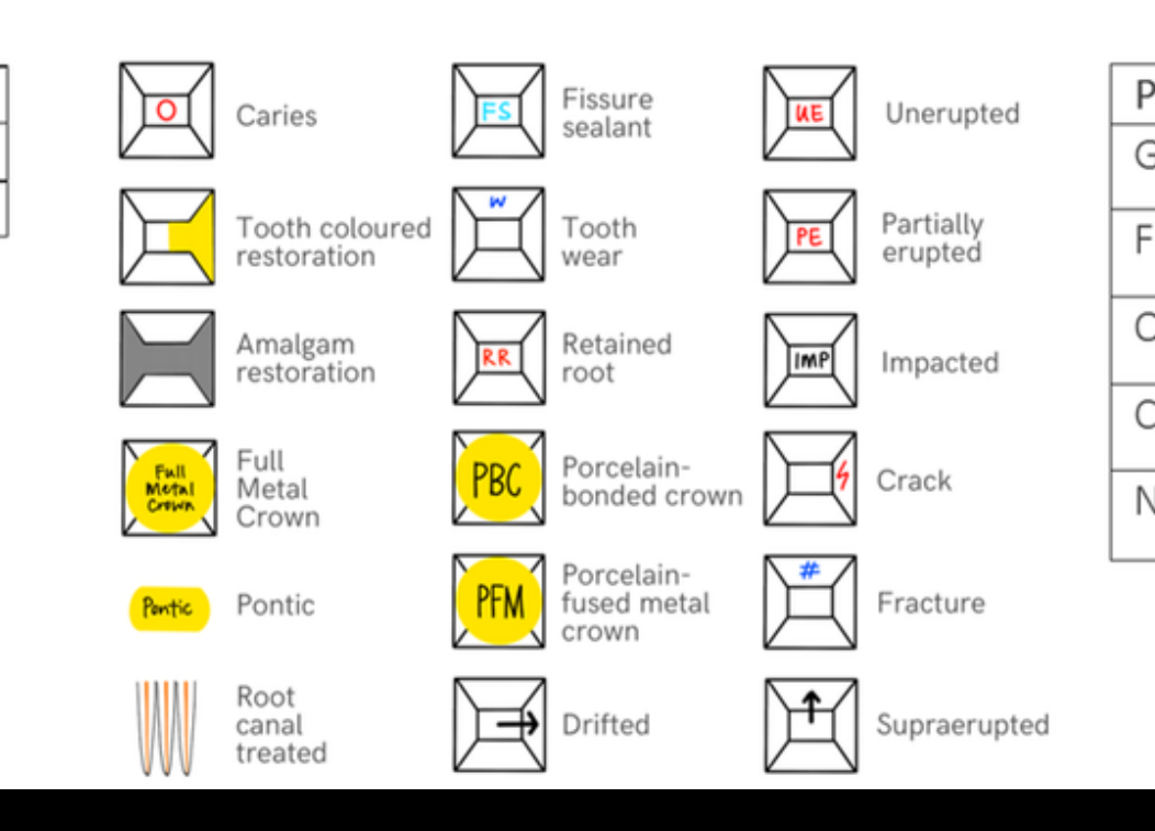
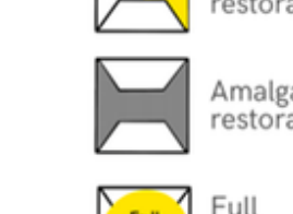
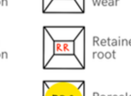
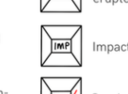
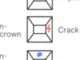
Charting legend:
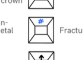
| Caries | Fissure sealant | Unerupted |
|---|---|---|
| Tooth coloured restoration | Tooth wear | Partially erupted |
| Amalgam restoration | Retained root | Impacted |
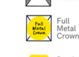
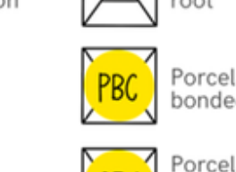
| Full Metal Crown | Porcelain-bonded crown | Crack |
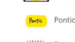
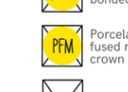
| P Pontic | PFM Porcelain-fused metal crown | Fracture |
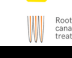
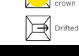
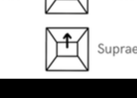
| Root canal treated | Drifted | Supraerupted |
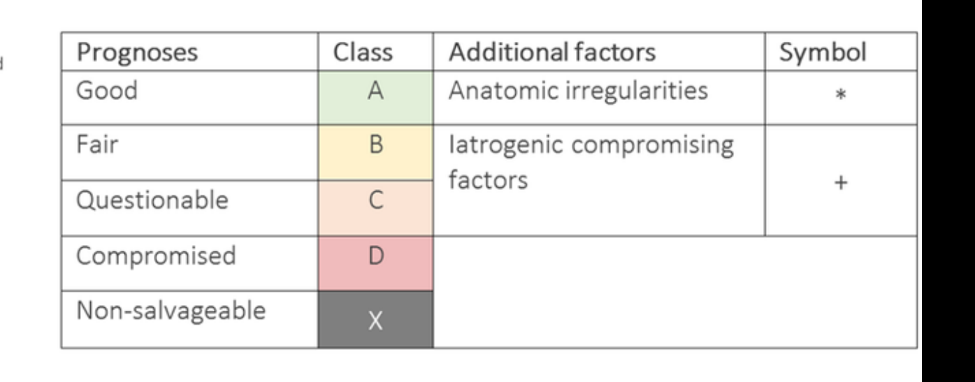
Prognosis classes:
| Prognoses | Class | Additional factors | Symbol |
|---|---|---|---|
| Good | A | Anatomic irregularities | * |
| Fair | B | Iatrogenic compromising factors | |
| Questionable | C | ||
| Compromised | D | ||
| Non-salvageable | X |
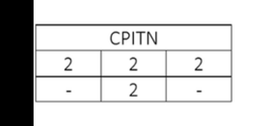
CPITN scores: 2, 2, 2, −, 2, −
Lecturer — Integrated Prognosis
Prognosis should be considered as a whole rather than tooth by tooth or condition by condition.
- Integrate periodontal and endodontic prognosis, restorability, occlusal requirements, and patient factors.
- Plan the prosthesis to accommodate the expected likelihood of future extractions or treatment changes.
 |  |  |
 |  |  |
 |  |  |
 |  |  |
 |  |  |
 |  |  |
 | 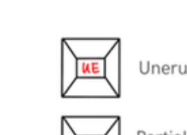 | 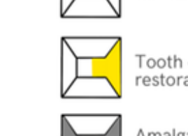 |
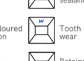 | 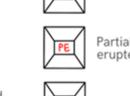 |  |
 |  |  |
 |  |  |
 |  |  |
 |  |  |
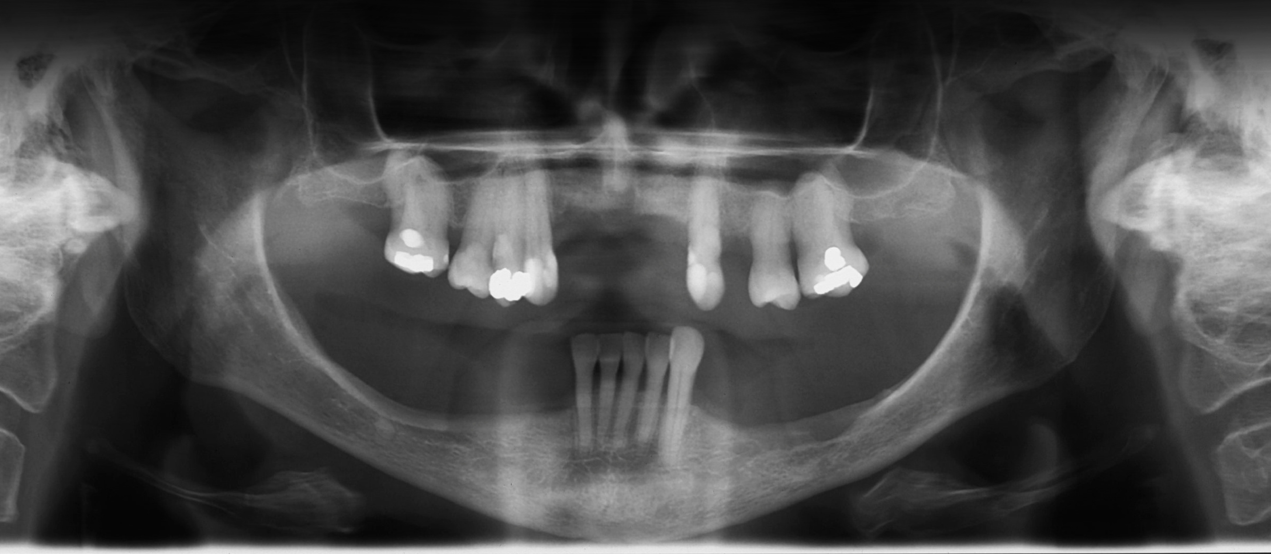
Comparing Acrylic and Co-Cr Prostheses1213
Acrylic prosthesis:
- Lightweight
- Poor retention
- Risk of fracture
Co-Cr prosthesis:
- Stronger
- Better retention
- More expensive
Acrylic14
- Changing dentition
- Questionable prognosis
- Future extraction likely
- Easy to modify / add teeth
- Transitional treatment
- Flexibility
Co-Cr
-
Rigid
-
Thin
-
Less tissue coverage
-
Design-controlled support & bracing
-
Potentially more cleansable
-
…in the right patient
-
Changing dentition
-
Questionable prognosis
-
Future extraction likely
-
Easy to modify / add teeth
-
Transitional treatment
-
Flexibility
-
Extensive caries or uncertain restorability of several teeth
-
Extremely mobile teeth
-
Generally lower cost
-
A well-made acrylic denture can be definitive, although it generally has greater tissue coverage than cobalt-chromium
-
Rigid
-
Thin
-
Less tissue coverage
-
Design-controlled support & bracing
-
Potentially more cleansable
-
…in the right patient
-
Less flexible when teeth are expected to be extracted or added later
Shared Decision Making With the Patient15
The patient is part of the design.
Biology + prognosis + maintenance + cost + time + expectations = SHARED DECISION
Lecturer — Previous Prosthesis
The patient’s previous prosthesis should be examined as part of the decision.
- A patient accustomed to a thin cobalt-chromium denture may not tolerate a thicker acrylic prosthesis.
- Determine what worked, what did not work, and how the new design can improve on it.
- Include the patient’s willingness to accept the time and cost involved in cobalt-chromium treatment.
Workflow Overview and Pathway Comparison1617
One patient journey. Two pathways.
| 1 | 2 | 3 | 4 | 5 | 6 | 7 | 8 | 9 | 10 | 11 |
|---|---|---|---|---|---|---|---|---|---|---|
| Primary impression | Preliminary articulation | Preliminary Try-in | Survey + design | Special Tray | Mouth prep | Definitive impression | Framework | MMR | Tooth try-in | Insert |
- Acrylic
- Primary impression
- Preliminary articulation
- Preliminary Try-in
- Survey + design
- Special Tray
- Mouth prep
- Definitive impression
- Framework
- MMR
- Tooth try-in
- Insert
-
Question marks indicate that a special tray, MMR, or tooth try-in may not be required in every case.
-
Acrylic
-
Co-Cr
-
Definitive impression
-
Special Tray?
-
Primary impression
-
Insert
-
Tooth try-in?
-
MMR?
-
Special Tray + design
-
Mouth prep
-
Preliminary articulation
-
Survey
-
Preliminary Try-in
-
MMR
-
Dintimont impression
-
Framework
-
Master-cast surveying
-
Framework try-in
 |  |
 |
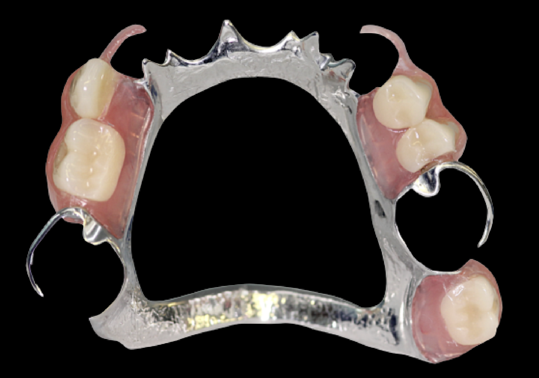
Acrylic RPD Workflow
- Primary impression
- Preliminary articulation
- Preliminary Try-in
- Survey + design
- Special Tray
- Mouth prep
- Definitive impression
- Framework
- MMR
- Tooth try-in
- Insert
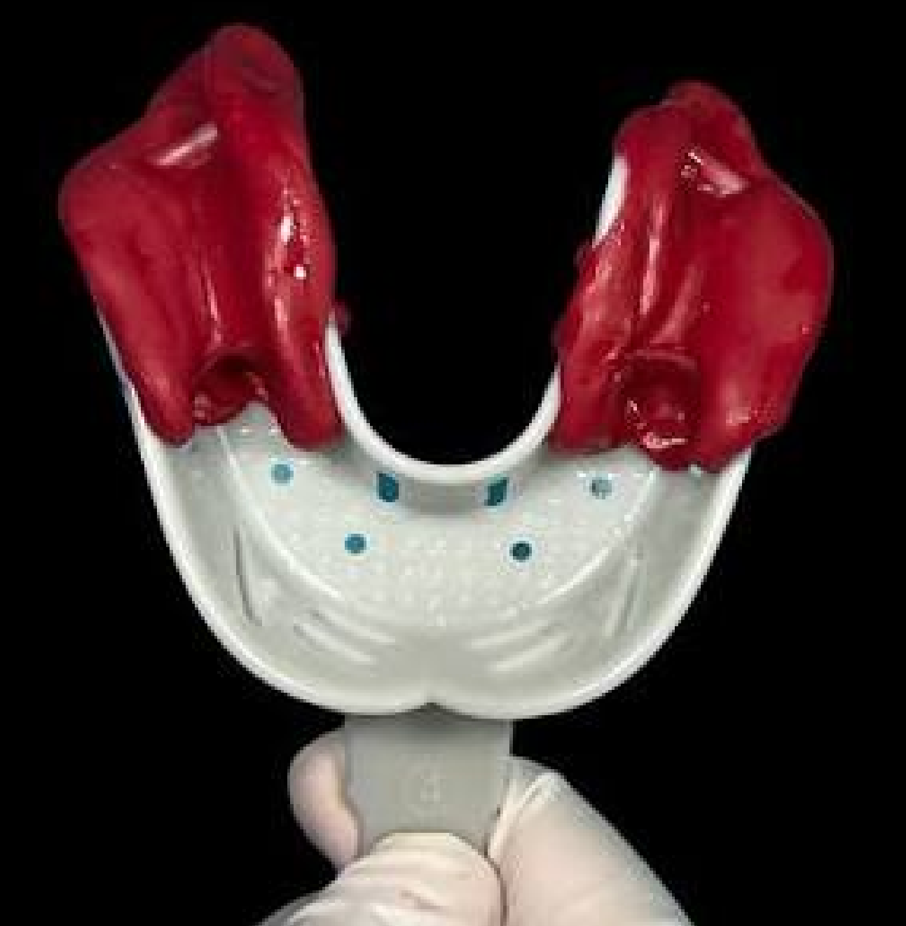
Primary Impression18
Aim: a diagnostic representation of the dentition and edentulous areas
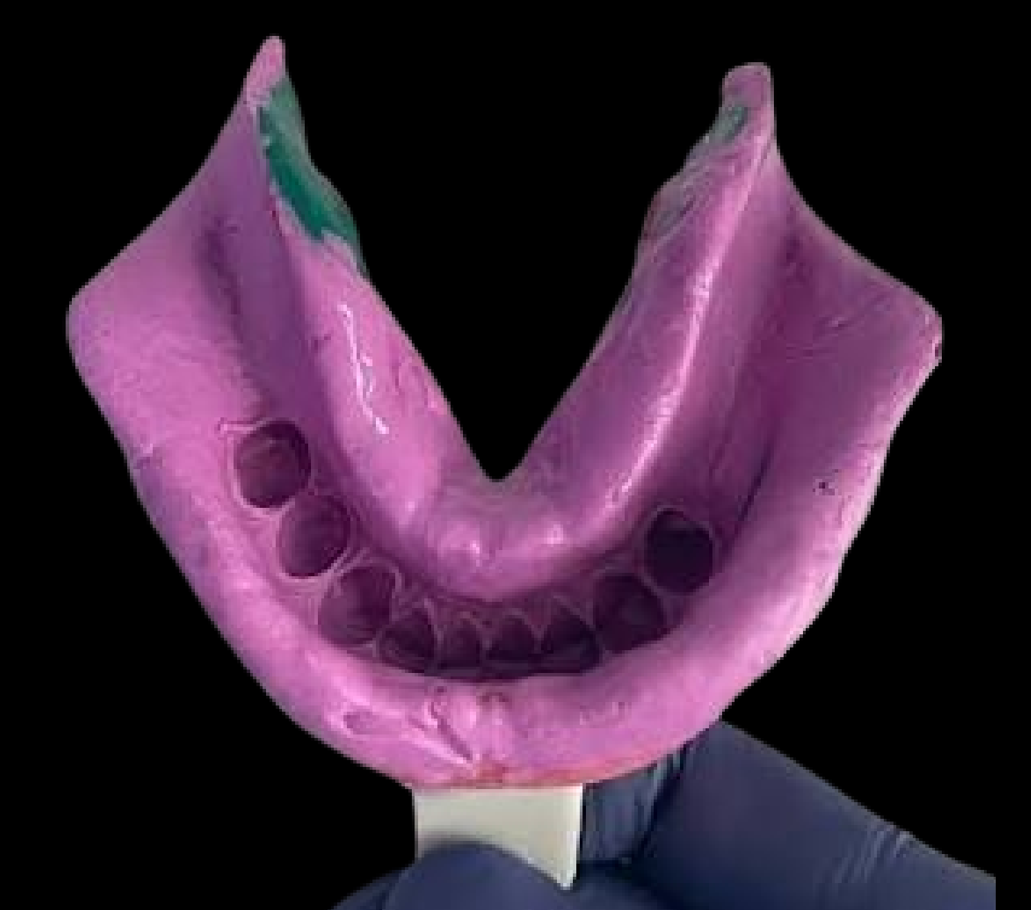
Lecturer — Primary Tray Modification
A stock tray is normally used for the primary impression, but it may need modification to obtain a useful preliminary model.
- The tray may be modified with compound, putty, green stick, or periphery wax.
- If it is short or contacts the ridge, it can be heated, widened, or extended.
 |  |
Need for a Secondary Impression
The acrylic workflow: 1. Primary impression → 2. Preliminary articulation → 3. Survey + design → 4. Special Tray → 5. Mouth prep → 6. Definitive impression → 7. Framework → 8. Try-in → 9. MMR → 10. Tooth try-in → 11. Insert.
Ask about the edentulous span and what the impression must achieve.
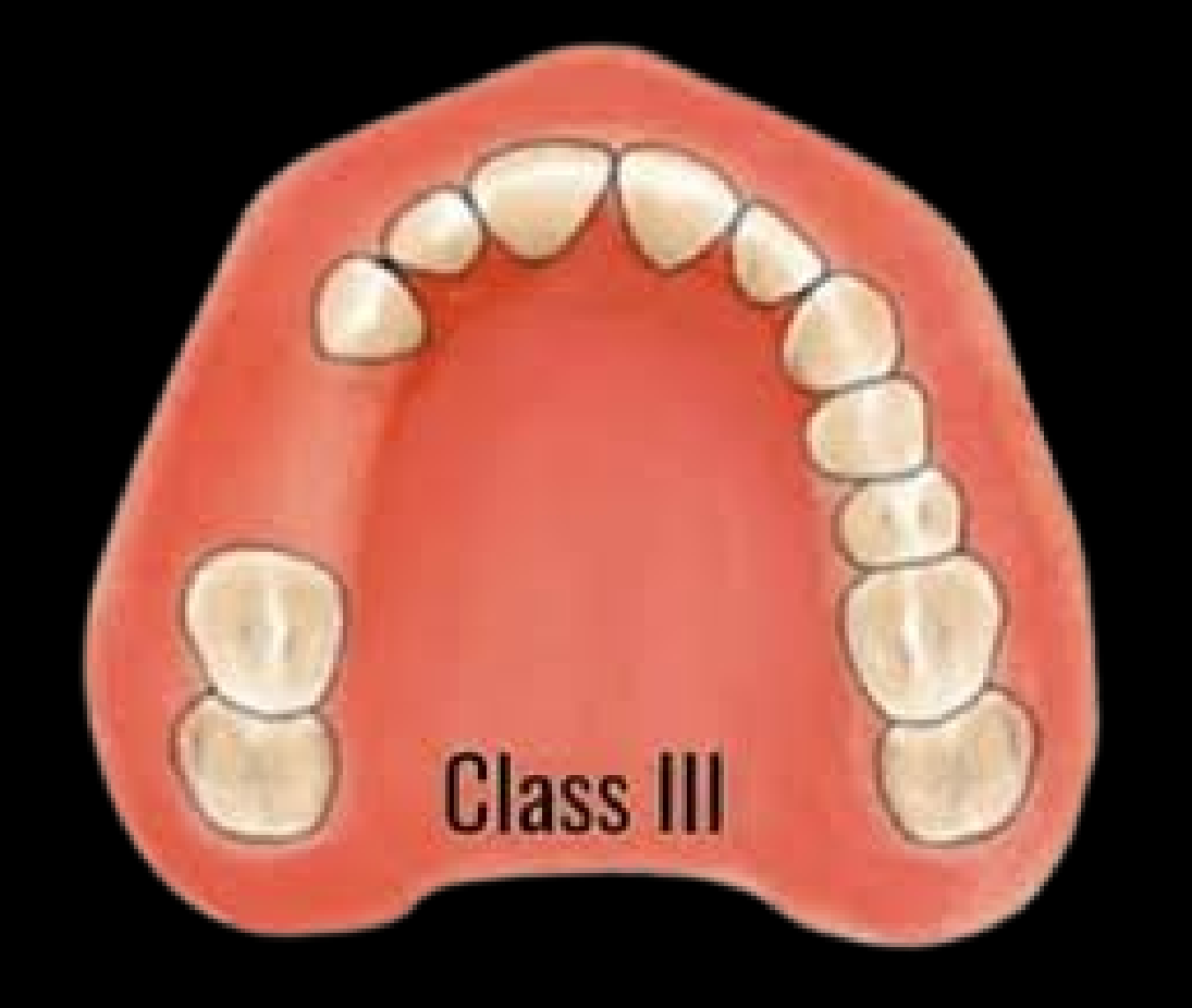
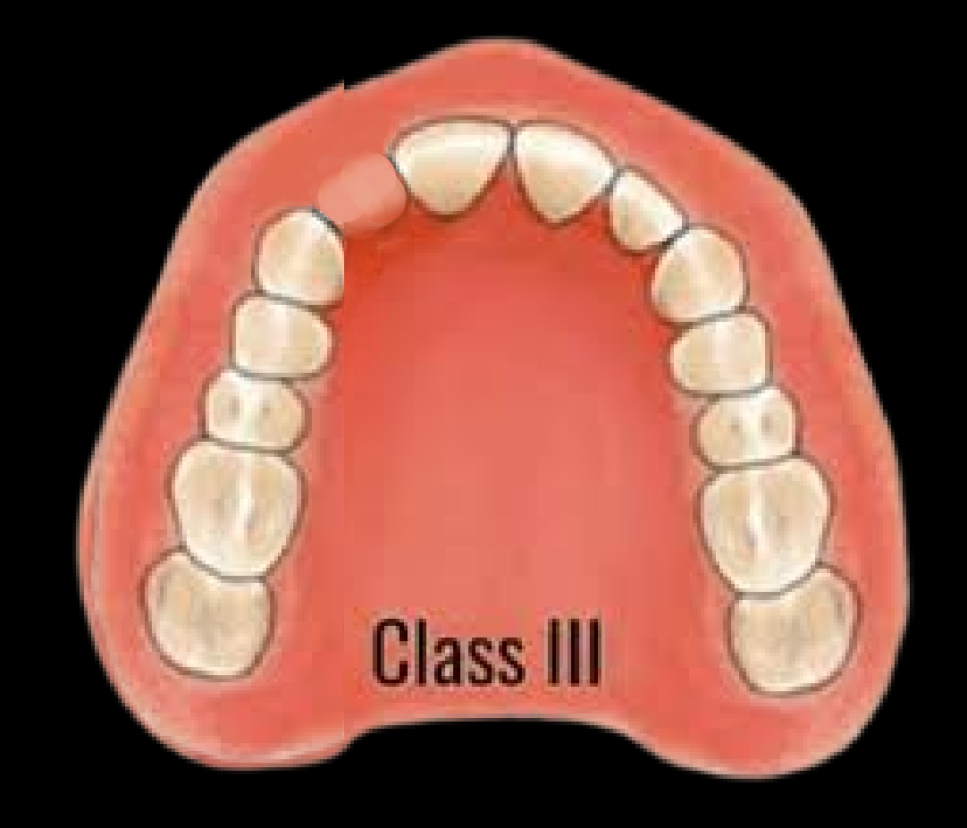
May Not Need19
- Short bounded saddle
- Single missing tooth
Ask about the edentulous span and what the impression must achieve.
Workflow: Primary impression → Preliminary articulation → Survey + design → Special Tray → Mouth prep → Definitive impression → Framework → Try-in → MMR → Tooth try-in → Insert (steps 1–11).
- Short bounded saddle
- Single missing tooth
 |  |
 |
Strongly Consider20
- Kennedy I / II free-end saddle
- Long Kennedy IV
- Large tissue-supported Kennedy III
Lecturer — Secondary Impression Criteria
A secondary impression may not be necessary when the case is tooth bounded or tooth supported, the edentulous space is short, and the primary alginate impression is sufficiently accurate.
- A short bounded space replacing two teeth may not require a special tray if the alginate impression is very good.
- A definitive impression should be strongly considered when the prosthesis is tissue supported, the acrylic must extend fully into the vestibule or sulcus, or the primary impression does not adequately capture the anatomy.
Special Tray21
Workflow: Primary impression → Preliminary articulation → Survey + design → Mouth prep → Definitive impression → Framework → Preliminary Try-in → MMR → Tooth try-in → Insert (steps 1–11; Special Tray is step 5).
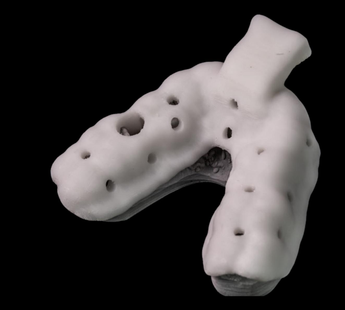
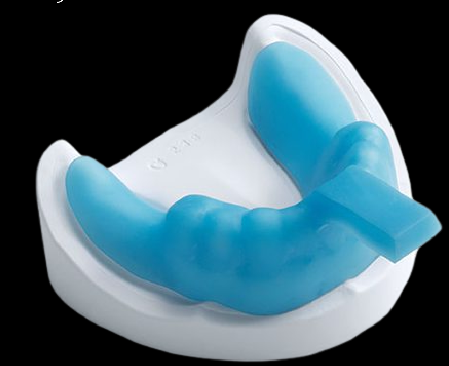
Perforated Tray22
- Alginate → 3mm spacer
 |  |
Non-Perforated Tray
- PVS
- Polyether
Both with a 2mm spacer.
Lecturer — Spacer Guidelines
These spacer values are general guidelines rather than absolute rules.
- A little more space may still function, but insufficient space may cause problems.
- The selected impression material should be used according to its instructions because different products may have different setting times and may not mix appropriately.
Workflow overview (steps 1–11, Special Tray is step 5): Primary, Prem. Artic., Prem. Try-in, Survey + design, Special Tray, Mouth prep, Def. Impression, Framework, MMR, Tooth Try-in, Insert.
Key Instruction23
The laboratory / technician needs to know what comes next
Lecturer — Bite Record Routine
A bite record should still be taken routinely, even when a full base and rim MMR may not be required.
- Take the required impressions, record the bite, assess whether stable contacts are present, and then decide whether a base and rim are required.
- For cases without stable contacts, a diagnostic base and rim may be requested, treating the patient similarly to a complete-denture patient when establishing vertical dimension.
 |  |
 |  |
What Must Be Specified on the Prescription
- Material planned
- Tray perforated / non-perforated
- Spacer requirement
- Purpose of impression → removable / fixed
Lecturer — Laboratory Prescription
The prescription should communicate enough information for the technician to understand the clinical intention rather than requiring the technician to guess the material or design.
- Specify the tray arch and whether tissue stops are required.
- State the intended prosthesis, such as an acrylic removable partial denture.
- A laboratory cannot be criticised for producing an unsuitable tray if the prescription did not provide enough information.
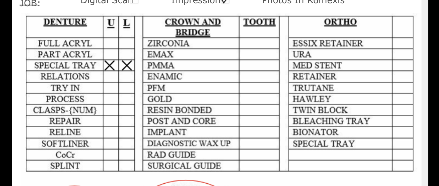
Digital Laboratory Request Form (OHCWA Laboratory Request)
- Temp Number: TEMP00000
- First Name: Peter
- Last Name: Parker
- Date Of Birth: 12/09/1954
- Lab Due Date: 09/09/2026
- Clinician: Stan Lee D-1922
- Operator ID: (blank)
- Select Group: DMD3 ✓, SPEC ✓; DMD4, DCD, GDP not selected
- JOB checkboxes: Digital Scan — [ ], Impression — [✓], Photos In Romexis
Material Selection Table
| DENT | U | L | CROWN AND BRIDGE | TOOTH | ORTHO |
|---|---|---|---|---|---|
| FULL ACRYL | ZIRCONIA | ESSIX RETAINER | |||
| PART ACRYL | EMAX | URA | |||
| SPECIAL TRAY | ☑ | ☑ | PMMA | MED STENT | |
| RELATIONS | ENAMIC | RETAINER | |||
| TRY IN | PFM | TRUTANE | |||
| PROCESS | GOLD | HAWLEY | |||
| CLASPS-(NUM) | RESIN BONDED | TWIN BLOCK | |||
| REPAIR | POST AND CORE | BLEACHING TRAY | |||
| RELINE | IMPLANT | BIONATOR | |||
| SOFTLINER | DIAGNOSTIC WAX UP | SPECIAL TRAY | |||
| CoCr | RAD GUIDE | ||||
| SPLINT | SURGICAL GUIDE |
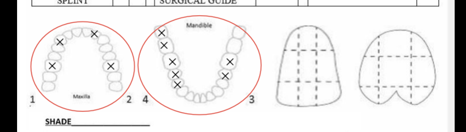
(Visual reference diagrams: dental arch templates + spacer drawings.)
Handwritten Instruction at Bottom of Form
INSTRUCTIONS Dear Lab, Please fabricate Upper and Lower Special tray according to the following:
- Maxillary perforated special tray with 3mm spacer for Alginate impression
- Mandibular non-perforated special tray with 2 mm for PVS impression with tissue stops
- Primary impression
- Preliminary articulation
- Survey + design
- Mouth prep
- Definitive impression
- Framework
- Preliminary Try-in
- MMR
- Tooth try-in
- Insert
- Special Tray
Instructions (Brief)24
Dear Lab,
Please make special tray.
 |  |
Instructions (Detailed)
Dear Lab,
Please fabricate Upper and Lower Special tray according to the following:
- Maxillary perforated special tray with 3mm spacer for Alginate impression
- Mandibular non-perforated special tray with 2 mm for PVS impression with tissue stops
| Step | Title | Description |
|---|---|---|
| 1 | SEAT | check: gross extension, seating, interference, sharp edges |
| 2 | FUNCTION | cheek/lip manipulation; tongue movements |
| 3 | TRIM | adjust areas that displace the tray |
| 4 | REASSESS | repeat the same movements |
Top timeline (1–11):
- Primary impression
- Preliminary articulation
- Preliminary Try-in
- Survey + design
- Special Tray
- Mouth prep
- Definitive impression
- Framework
- MMR
- Tooth try-in
- Insert
Definitive Impression
Border Moulding Decisions
Does every special tray need border moulding?
Border mould when functional base extension matters.
Lecturer — Border Moulding Assessment
Border moulding is not required in every partial denture; it is mainly considered when full extension and tissue support are important.
- Before adding impression material, move the cheeks, lips, and tongue to assess the tray.
- If the tray moves substantially during functional movements, the corresponding border may be overextended.
- The goal is no significant movement during functional movements, rather than absolutely no movement under all hand pressure.
Common Situations
- Kennedy I / II free-end saddle
- Long Kennedy IV
- Large tissue-supported saddle
- Posterior maxillary extension where the denture base extends into functionally relevant soft tissue areas
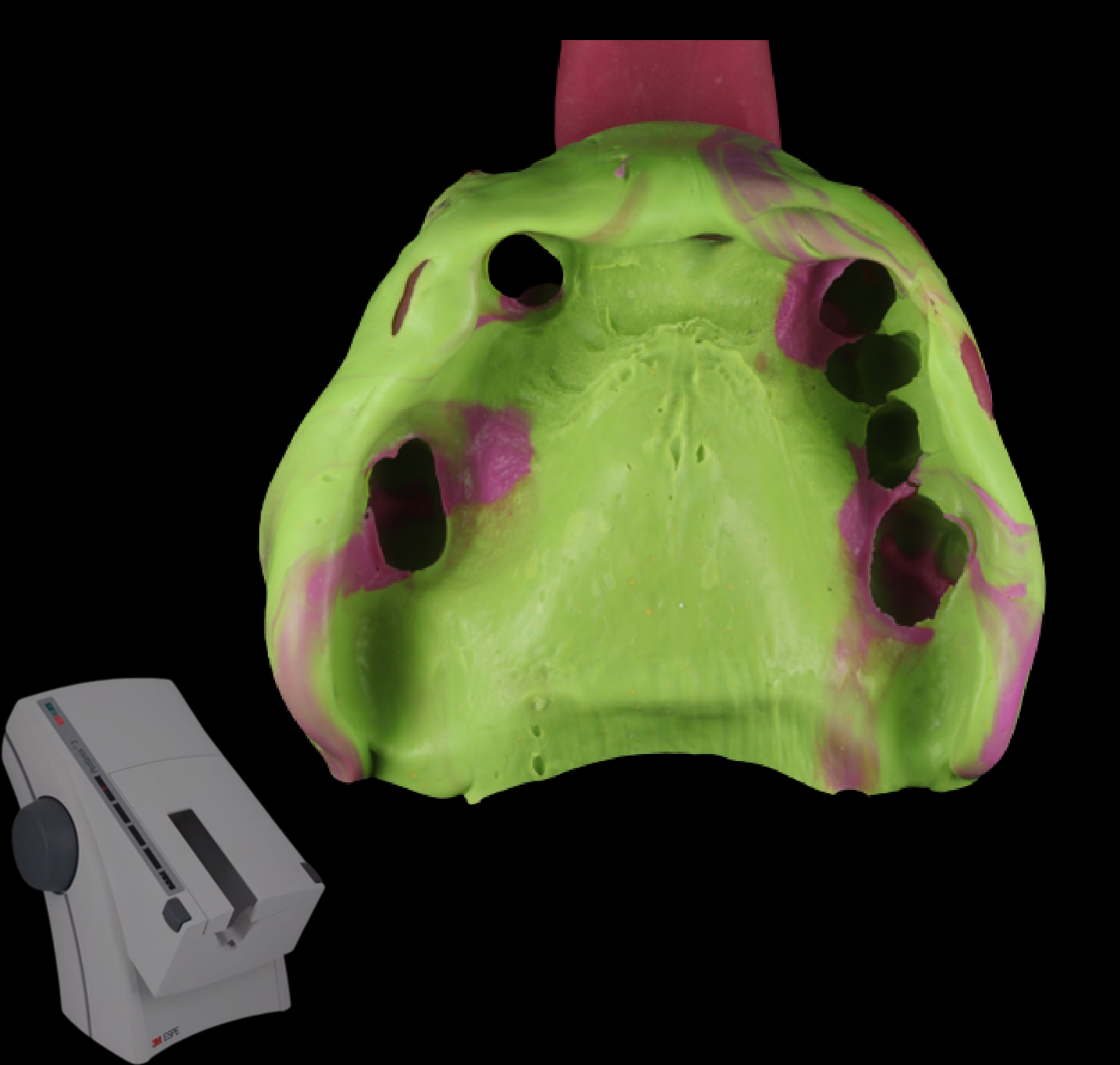
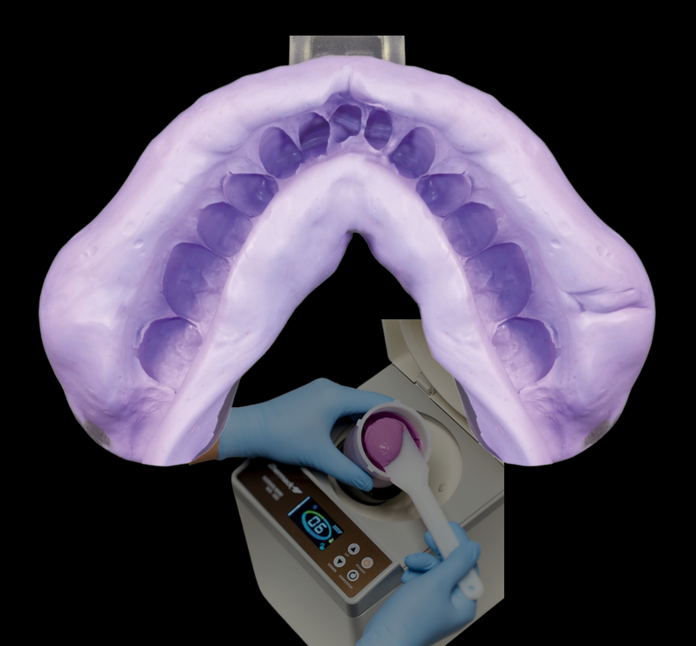
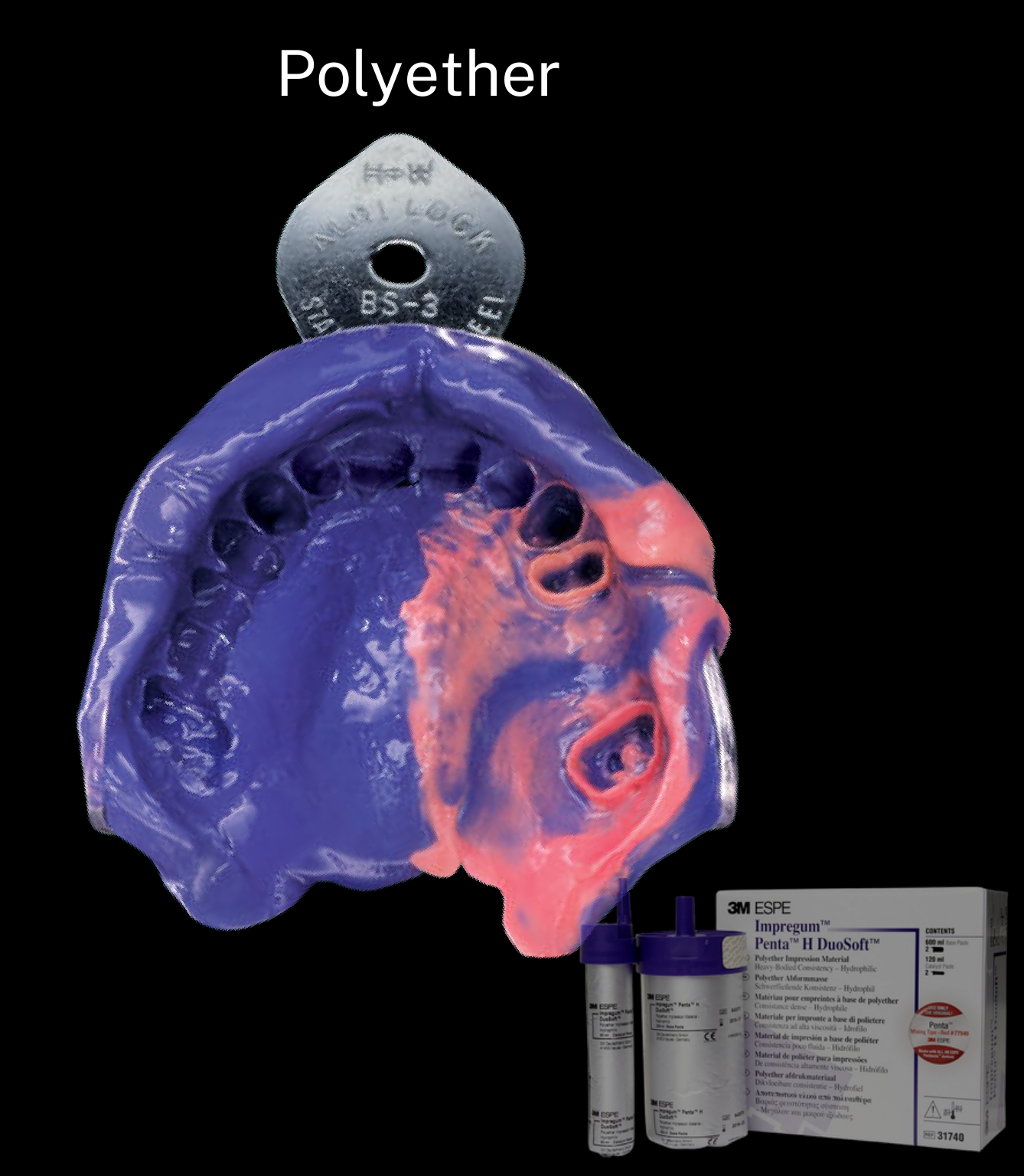
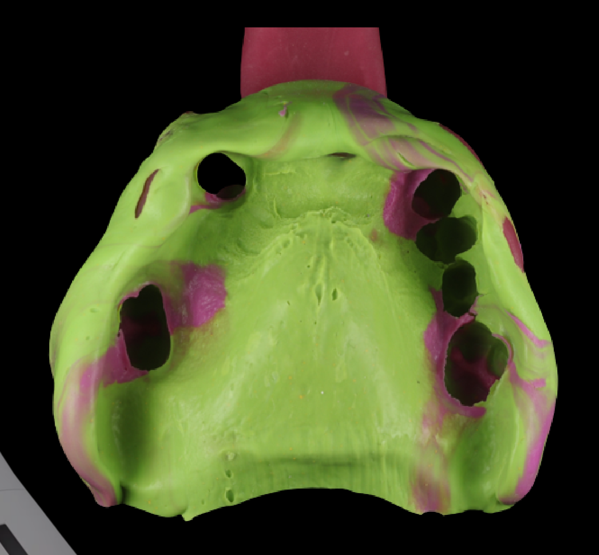
Impression Material Selection252627
Which material?
- Polyvinyl Siloxane
- Alginate
- Polyether
Which material?
-
Polyvinyl Siloxane
-
Alginate
-
Polyether
-
Common
-
Rare
Polyvinyl Siloxane (PVS)
- Heavy
- Medium
Lecturer — Impression Material Selection
At the dental school, PVS, including medium and light body combinations, was commonly used, although different clinicians may prefer different combinations such as heavy and light body.
- Alginate can provide an acceptable definitive impression when the material and technique are appropriate.
- Experienced clinicians may use alginate for final impressions, but the alginate used and the clinician’s familiarity with it influence the result.
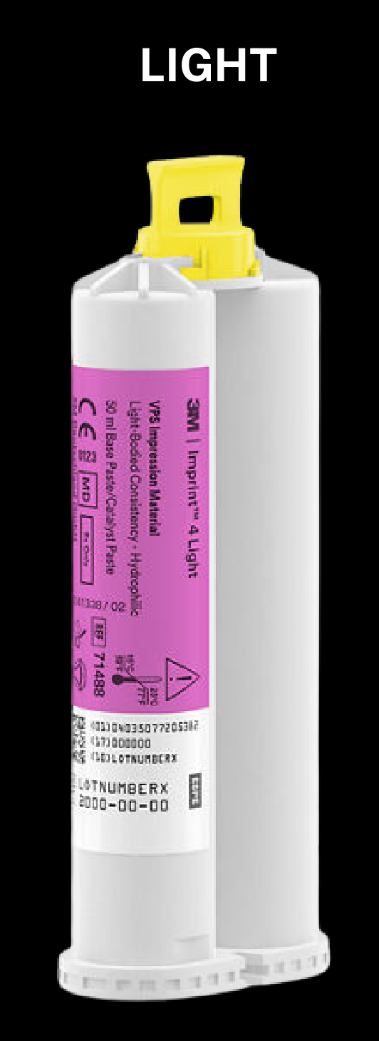
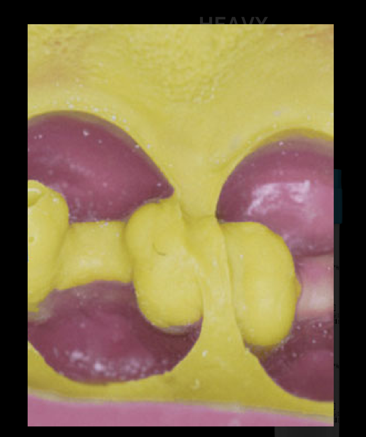
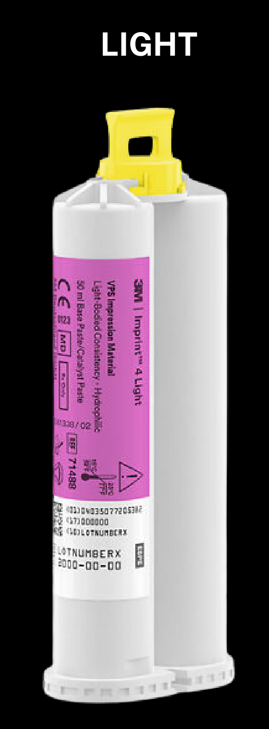
Why Light Body?28
Where detail matters:
- Rest seats
- Guide planes
- Prepared tooth surfaces
- Lingual plate contact
- Palatal plate contact
Dental model showing impression technique; injectable dental implant sleeve.
Lecturer — Light Body Placement
Light body is useful for capturing surface detail in areas where a heavier material may drag or fail to record anatomy.
- It may be placed on the teeth, tissues, in the tray, or in selected areas requiring greater surface detail.
- For a straightforward acrylic denture, medium-body material may be sufficient.
 |  |
Block Out of Undercuts
Spot the Risk
- Black triangles / open embrasures / large interdental spaces
- Gingival recession
- Tipped teeth
- Bridge or pontic undercuts
- Mobile / periodontally compromised teeth
Block Out
- Periphery wax
- Light-cure gingival barrier
- PTFE / Teflon tape
- Oraseal
- Temporary restorative material
Lecturer — Undercut Block-Out
Undercuts should be blocked out when impression material may lock into them, especially with polyether, heavy PVS, or deep interproximal and tooth undercuts.
- Polyether becomes very rigid and should not be used without blocking significant undercuts.
- Removal may otherwise require sectioning the tray or cutting the impression and may risk soft-tissue injury.
- Block-out should prevent locking while still allowing the material to extend into the required area.
Assessing Impression Quality
Did it record what I needed?
Lecturer — Impression Defects
The impression should be assessed before acceptance for defects that affect the planned denture area.
- Check for bubbles, drags, tears, or gaps, as well as the ridge, vestibular anatomy, abutments, rest seats, and guide planes.
- A defect between teeth may be acceptable if no acrylic or denture component will occupy that area.
- A major defect in a retromolar pad or buccal shelf area is not acceptable when those areas are required for support or extension.
Tooth-Supported / Bounded Saddle
- Rest seats / guide planes
- Saddle anatomy
- Path-of-insertion information and relevant tooth surfaces
Free-End / Long Saddle
- Abutment teeth
- Entire denture-bearing area
- Buccal + lingual extension
- Retromolar pad / tuberosity
- Functional peripheral form
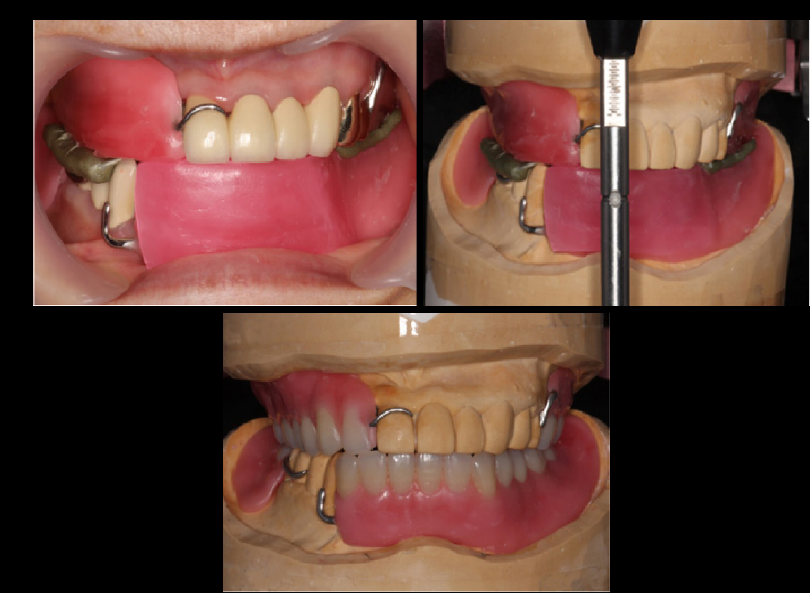
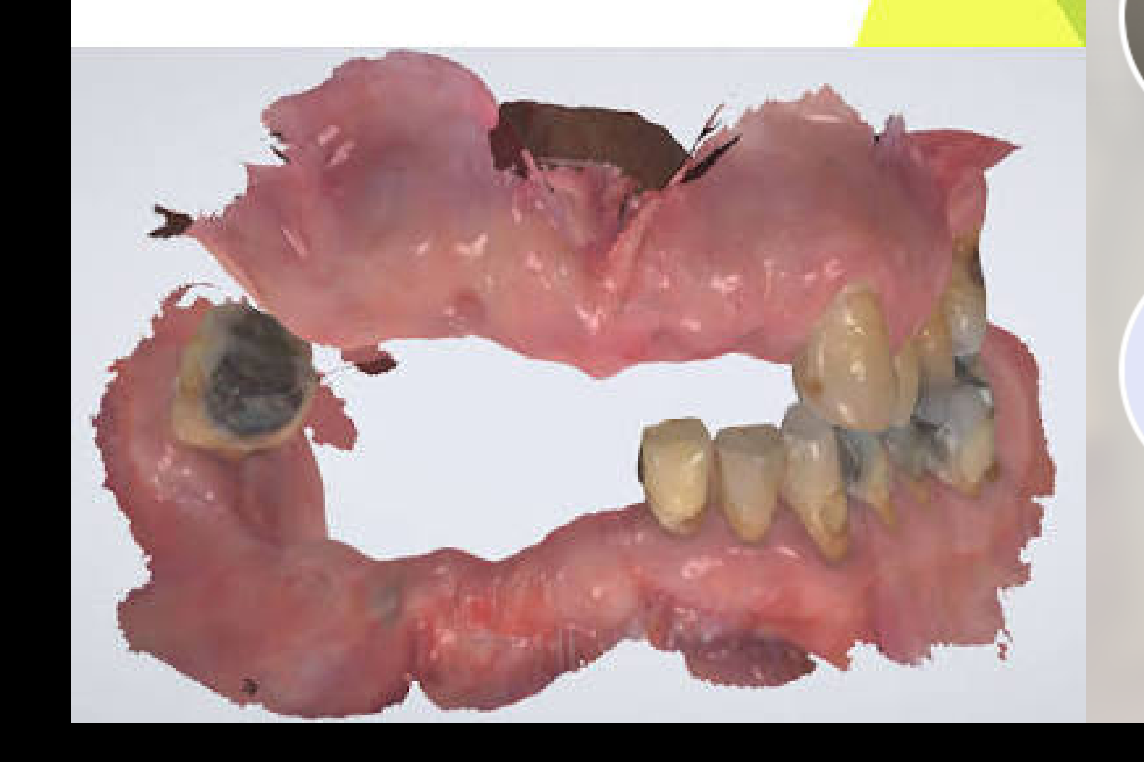
Maxillomandibular Records2930
 |  |  |
 |  |  |
 |  |  |
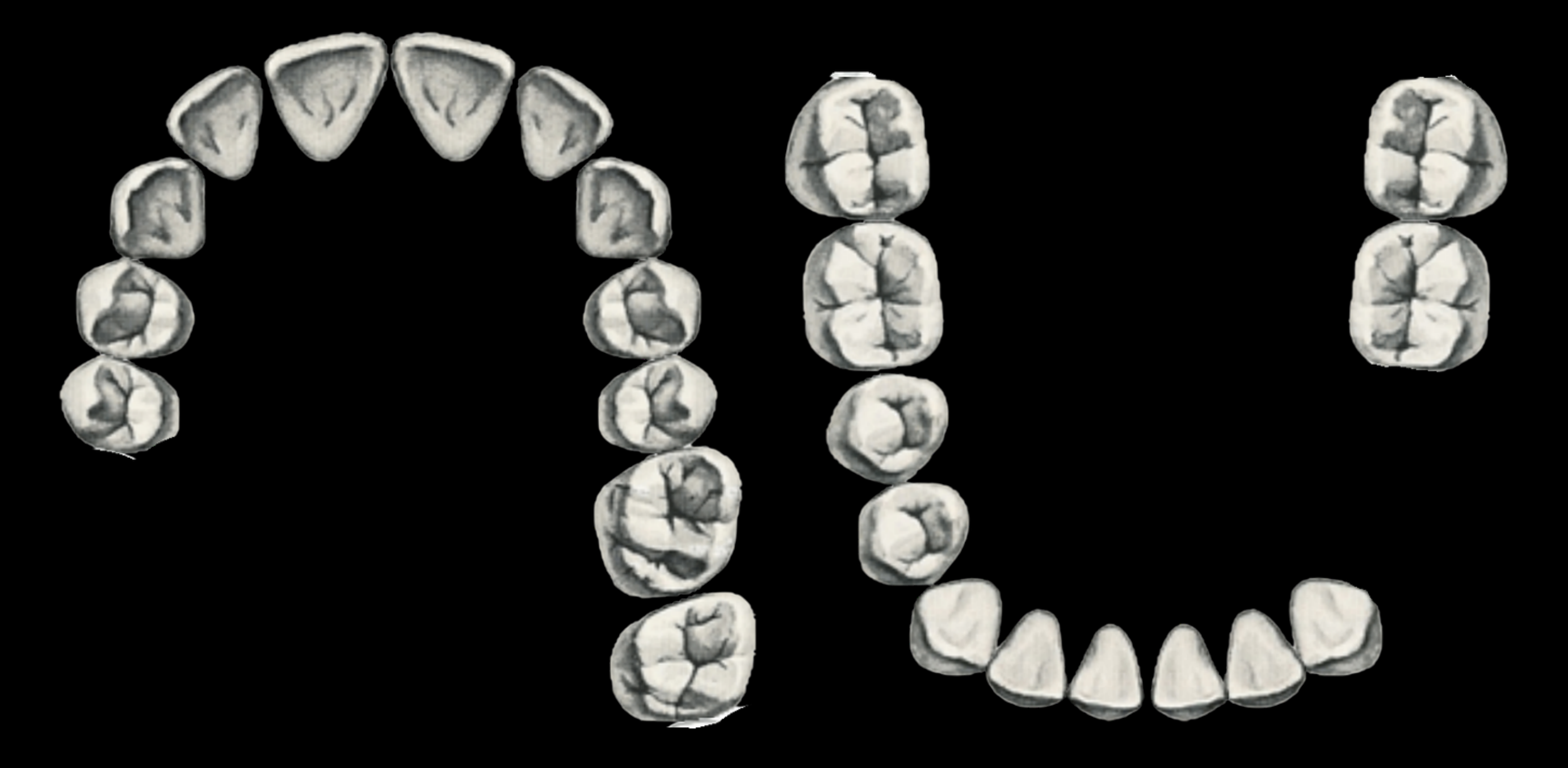
When Do I Need an MMR?31
Required / Essential:
- Kennedy I / II free-end saddle
- Long Kennedy IV
- Unstable occlusal stops
- VDO change
Not essential:
- Kennedy III (when hand articulation is possible)
Procedure Timeline32
-
Primary impression
-
Preliminary articulation
-
Preliminary try-in
-
Survey + design
-
Special tray
-
Mouth prep
-
Definitive impression
-
Framework
-
MMR
-
Tooth try-in
-
Insert
-
Primary impression
-
Preliminary articulation
-
Preliminary try-in
-
Survey + design
-
Special tray
-
Mouth prep
-
Definitive impression
-
Framework
-
MMR
-
Tooth try-in
-
Insert
Do not ask only:
“Can the patient bite together?”
Ask:
“Can the technician articulate these casts predictably?”
- Primary impression
- Preliminary articulation
- Preliminary try-in
- Survey + design
- Special tray
- Mouth prep
- Definitive impression
- Framework
- MMR
- Tooth try-in
- Insert
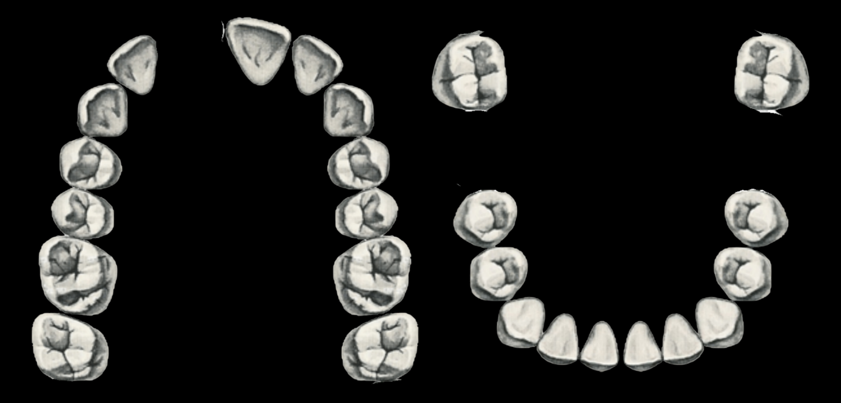
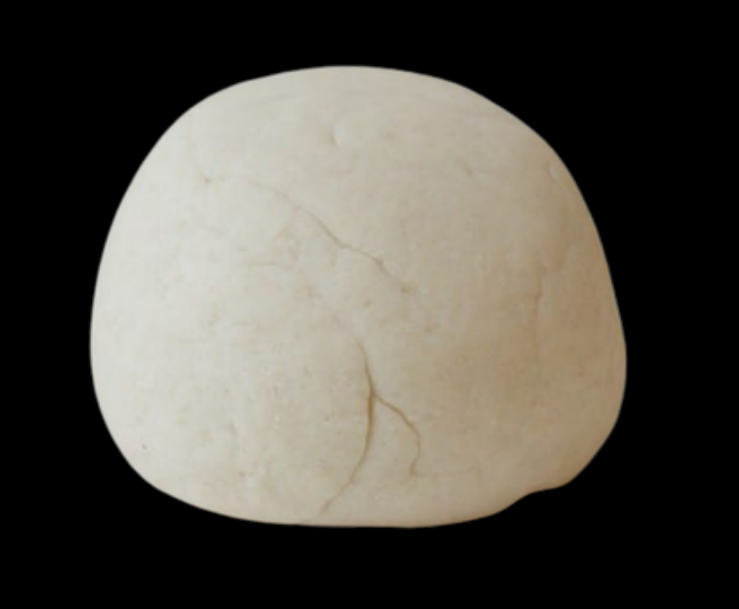
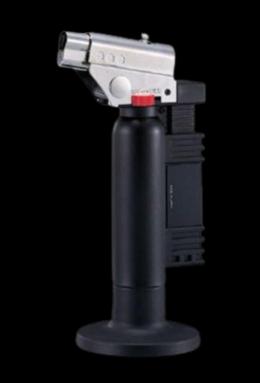
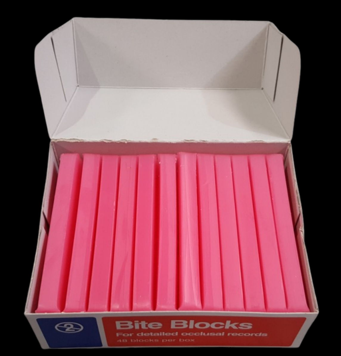
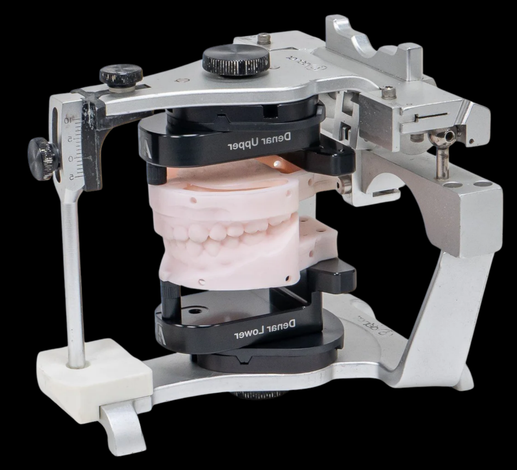
Cast-Rocking Test33
Practical MMR guide for acrylic RPDs — “cast-rocking test”
Put the models together:
- Are they stable?
- Are they rocking / sliding?
Lecturer — Bite Record Checking
The bite record itself must be checked before it is accepted.
- Look for perforations and bubbles, confirm that the contacts correspond to the patient’s mouth, and remove excess material from interproximal areas.
- A record extending into interproximal areas may prevent the casts from seating properly and create an artificially open articulation.
 |  |
 |  |
Can I Scan the Bite?34
More predictable:
- Short bounded saddle
- Stable teeth
- Good access + moisture control
- Reliable occlusal landmarks
- Minimal tissue displacement
More challenging:
- Long edentulous span
- Free-end saddle
- Mobile / displaceable tissues
- Functional border required
- Limited access or difficult tongue/cheek control
- Few stable occlusal landmarks
The scan can look beautiful… but the bite can still be wrong.
Always validate the digital record clinically.
Lecturer — Digital Bite Scanning
Digital bite scanning becomes more difficult with free-end saddles, long edentulous spaces, mandibular scans, saliva, or a lack of posterior contacts.
- Examine the digital occlusion before exporting the record; a contact-only display may show that the scanner has failed to identify contacts present clinically.
- When following a conventional workflow, remain within that workflow rather than moving unnecessarily between digital records and printed models.
Guidelines for Digital Interocclusal Records: Part 1 – Dentate and Partially Dentate Patients
Mar 04, 2026 // 15 min read
Ahmad Hendawi, Sheryl Teo, Adam Hamilton, Aaron Wong
DOI: 10.63580/ITI.FI.45775

Tooth Try-In or Direct Finish
Tooth Try-In Is Preferred35
- Multiple teeth
- Aesthetic zone
- Uncertain tooth position
- Occlusal uncertainty
- Altered VDO
- Clinician/student uncertainty
Direct Finish May Be Reasonable
- Single straightforward tooth
- Good neighbouring references
- Stable occlusion
- Minimal aesthetic risk
Lecturer — Shade Documentation
When direct finishing is selected, a shade tab and a photograph of the shade in the patient’s mouth should be sent to the laboratory.
- The photograph helps the technician verify the shade under the relevant clinical conditions.
Tooth Try-In: What Are You Approving?
- Tooth position
- Aesthetics
- Phonetics
- Occlusion
- VDO (where relevant)
- Patient acceptance
Lecturer — Try-In Assessment
The try-in should also be assessed for the smile line, canine line, midline, tooth size and shape, shade, retention, stability, and patient satisfaction.
- The patient should confirm that the appearance is acceptable before processing.
- Vertical dimension can be checked by comparing natural tooth contact with denture tooth contact using shim stock between the same natural teeth with and without the denture.
Insert
DO NOT JAM IT IN!
Path of Insertion36
- Posterior → anterior?
- Right → left?
- Simultaneous seating?
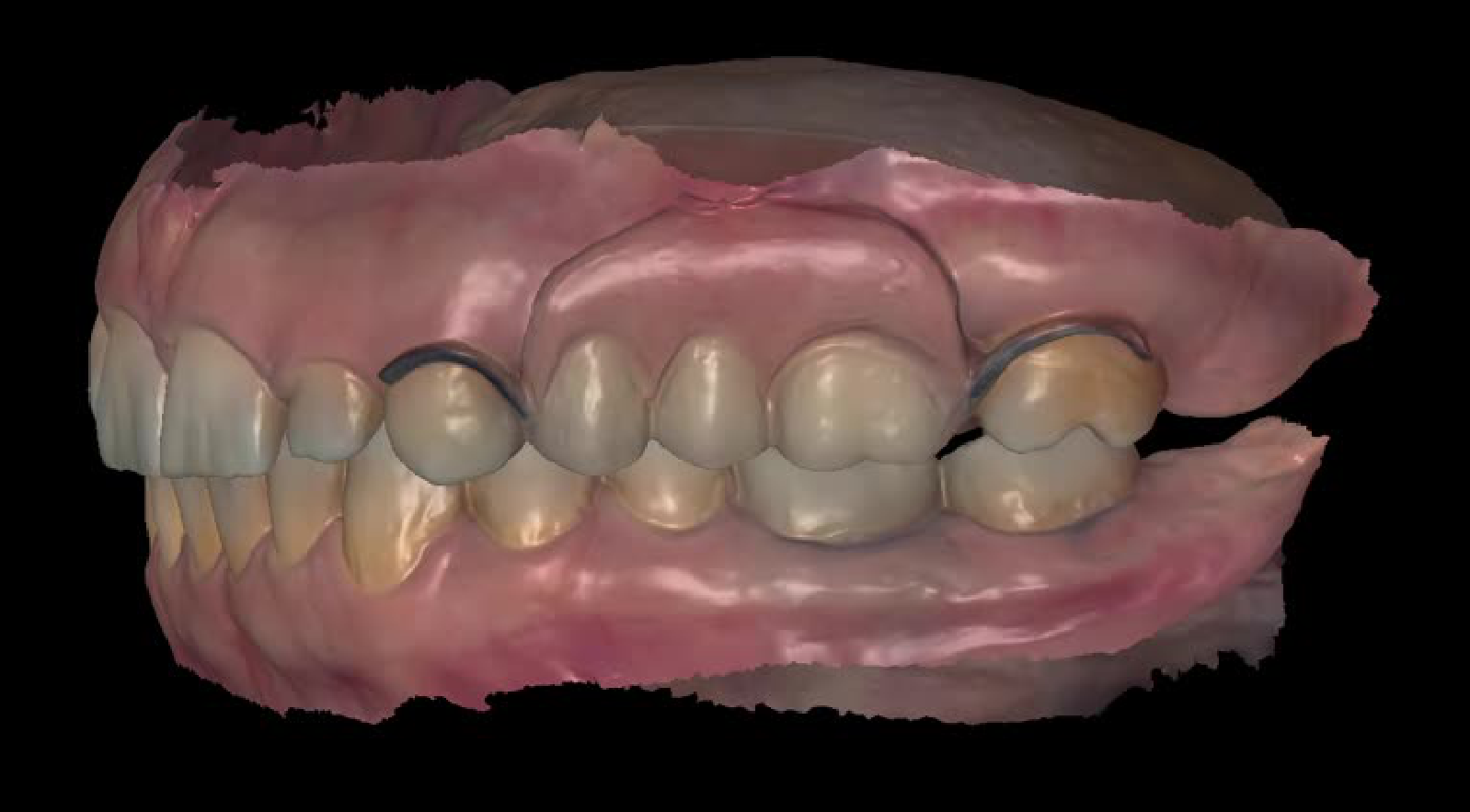
Look for the First Contact, Then Adjust Conservatively
- Rigid acrylic interface
- Clasp
Lecturer — Conservative Insertion Adjustment
Adjustments should be gradual: identify the first contact, remove a small amount of material, reseat the denture, and reassess.
- Avoid large adjustments or prolonged adjustment without reassessing the cause.
- Over-trimming can open embrasures and cause food packing.
Lecturer — Surveyed Crown Risk
For a cracked tooth being considered for a surveyed crown, the patient should be informed that the tooth may fail.
- A crown may brace the tooth, but adding a rest may affect the risk.
- The design should be assessed and approved before treatment.
Co-Cr RPD Workflow
Why Consider Co-Cr
Acrylic vs Co-Cr
Acrylic
- Changing dentition
- Questionable prognosis
- Future extraction likely
- Easy to modify / add teeth
- Transitional treatment
- Flexibility
Co-Cr
- Rigid
- Thin
- Less tissue coverage
- Design-controlled support & bracing
- Potentially more cleansable
…in the right patient
Why Consider Co-Cr37
Workflow Overview38
- Primary impression
- Preliminary articulation
- Preliminary try-in
- Survey + design
- Special tray
- Mouth prep
- Definitive impression
- Framework
- MMR
- Tooth try-in
- Insert
Process Comparison: Acrylic vs Co-Cr
| Process | Acrylic | Co-Cr |
|---|---|---|
| Primary impression | Green | Green |
| Preliminary articulation | Green | Green |
| Preliminary try-in | Yellow | Green |
| Survey + design | Green | Green |
| Special tray | — | — |
| Mouth prep | — | Green |
| Definitive impression | — | — |
| Framework | — | Green |
| MMR | — | Green |
| Tooth try-in | — | — |
| Insert | — | — |
Preliminary Articulation
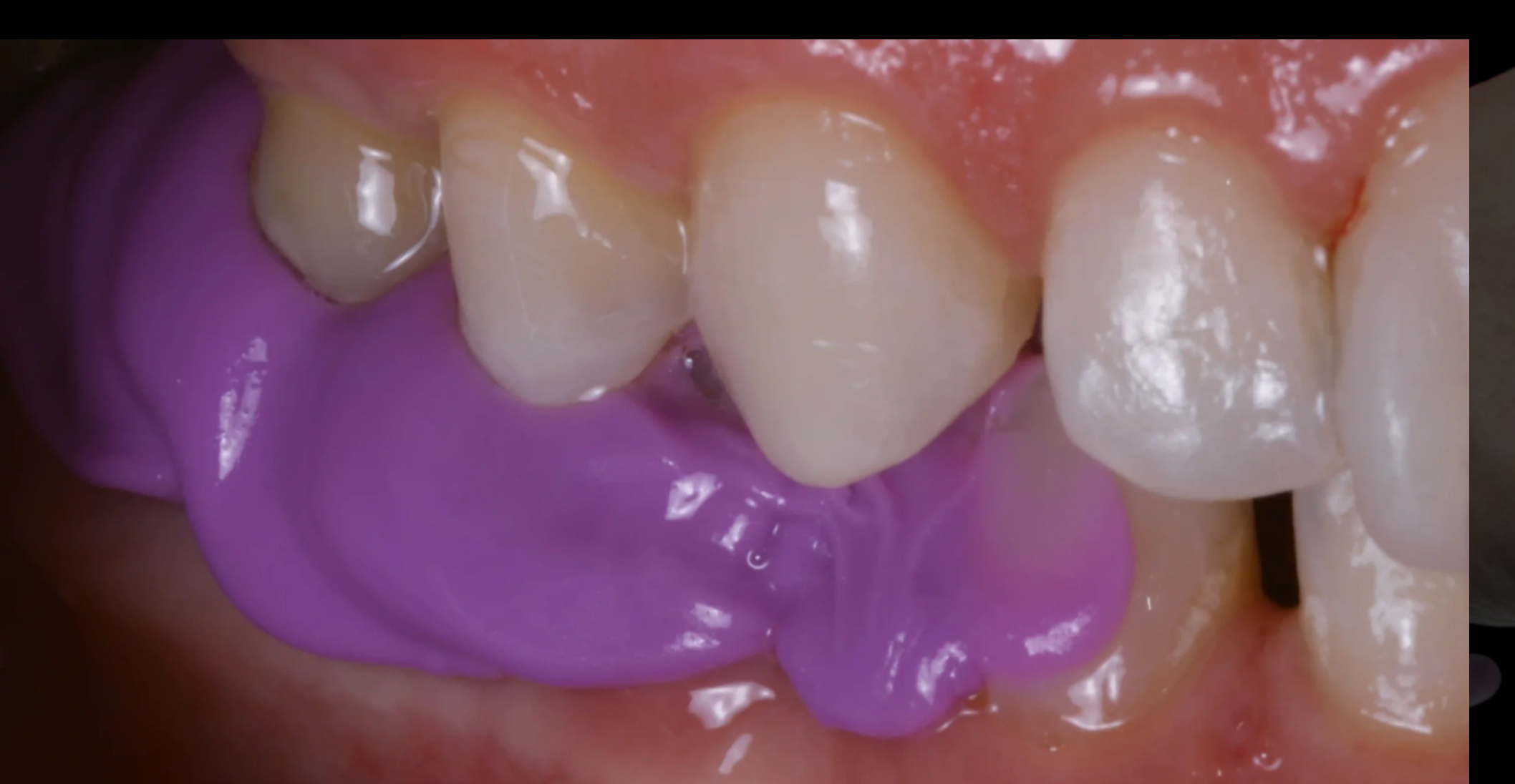
How Can I Articulate the Diagnostic Casts?39
PVS bite registration
Diagnostic MMR
- Base and occlusal rim fabricated intraorally / on the study model, or requested from the laboratory
 |  |
 |
Preliminary Try-In
Sometimes you need the teeth before the metal.
Consider Diagnostic Tooth Arrangement When
- Anterior tooth position is uncertain
- Class II / III interarch relationship
- Limited prosthetic space
- Framework must support an unusual tooth position
Establish tooth position first, then design the framework accordingly.
Survey and Design
What Does the Preliminary Survey Tell You?40
The survey answers:
-
Undercuts
-
Path of insertion
-
Interferences
-
Support and guidance
-
Rest locations, retentive and reciprocal clasp positions, indirect retention, and available prosthetic space Survey → Design → Prepare
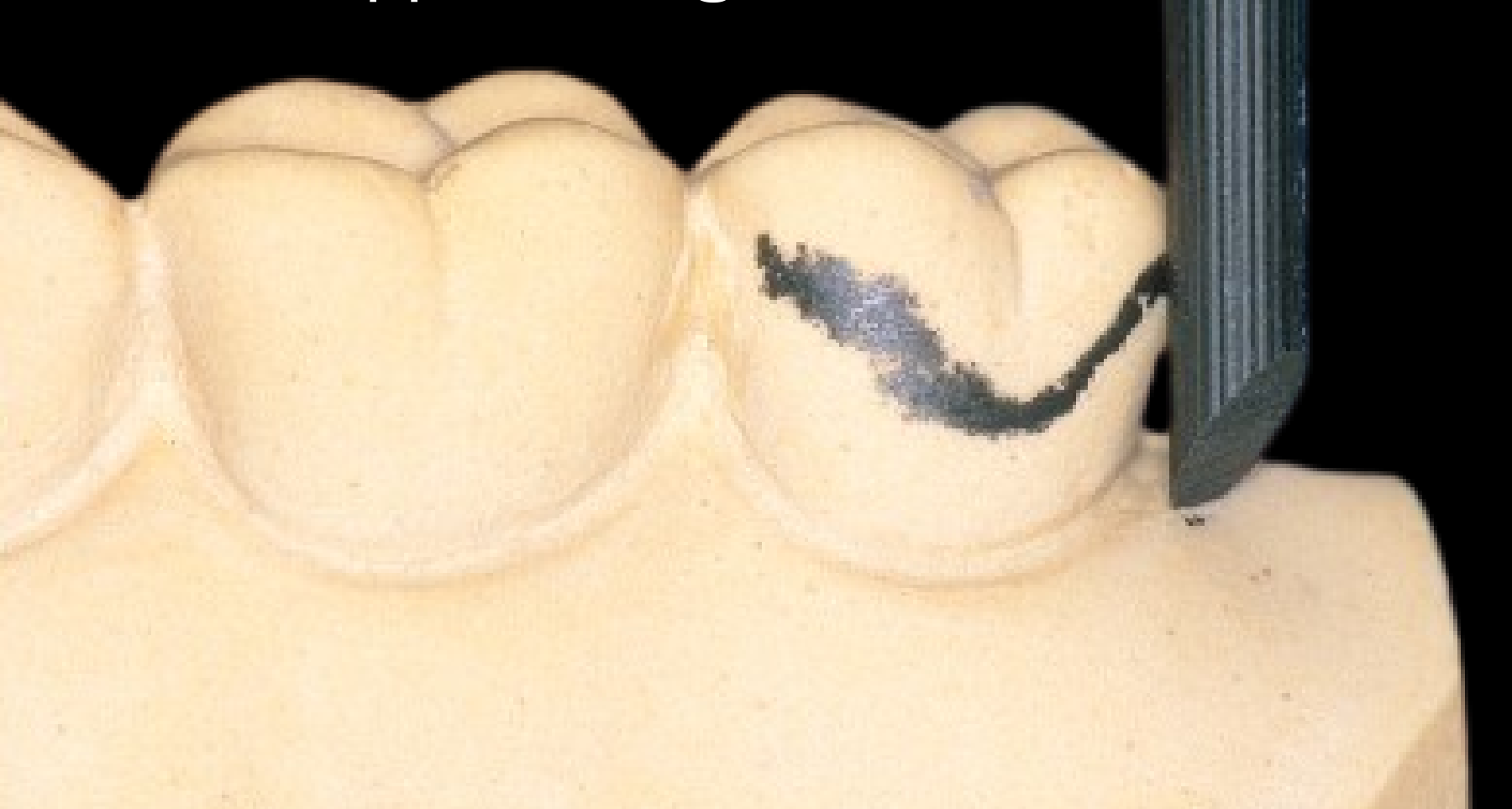 | 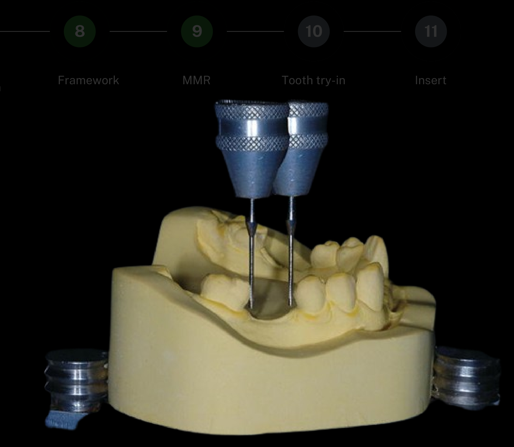 |
Surveyed Diagnostic Cast Includes
- Survey line
- Undercut gauge
- Proposed rest
- Guide plane
- Path arrow
Lecturer — Articulated Casts
The survey should be reviewed on articulated casts when occlusion and available space are relevant.
- The articulated casts should remain on an articulator during assessment.
- Two unmounted casts do not provide the same information.
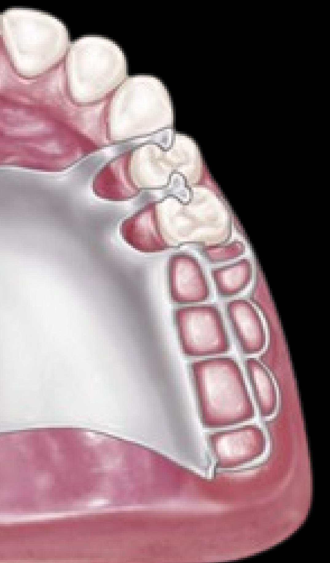
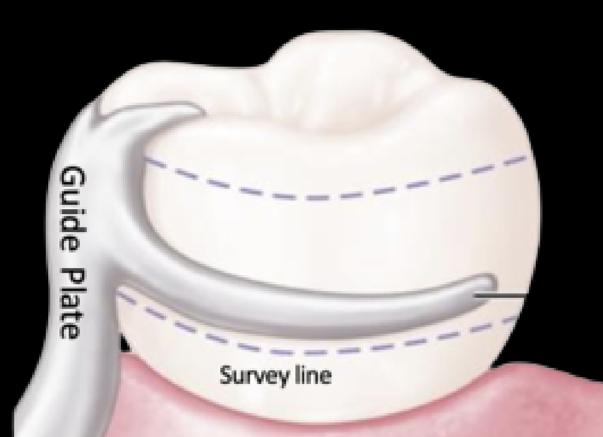
Mouth Preparation
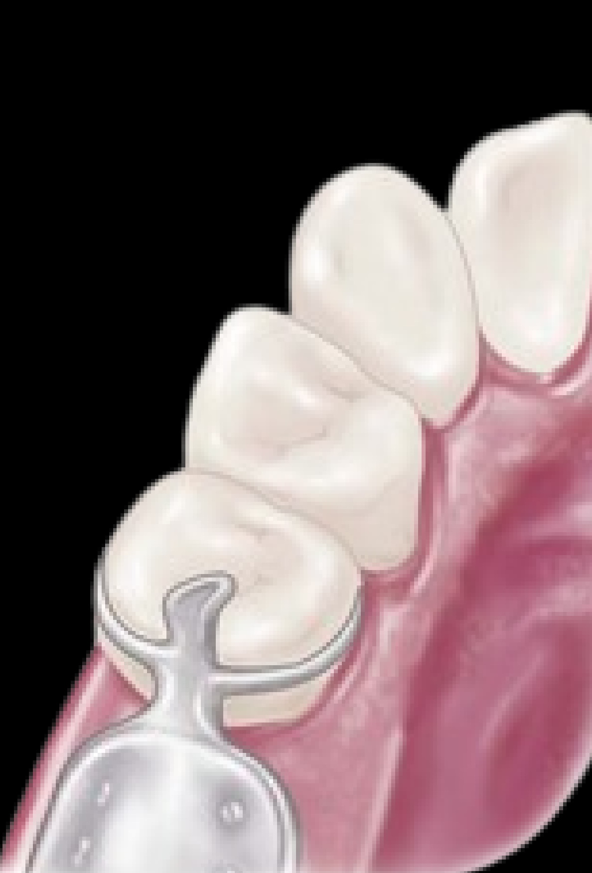
Mouth Preparation Is Design-Driven41
Every preparation should have a reason.
- Rest seats
- Guide planes
- Enamel recontouring
- Interference reduction where appropriate
Lecturer — Rest Seat Preparation
A rest seat may not require preparation when there is sufficient opposing space and the metal can sit on the tooth without creating an occlusal interference.
- A rounded marginal ridge may provide a favourable situation.
- A deep V-shaped area is more likely to require preparation.
 |  |
 |
Survey Master Model
Re-Survey the Master Cast42
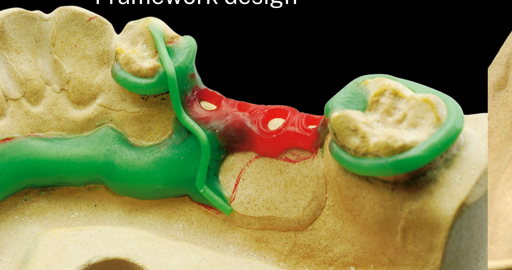
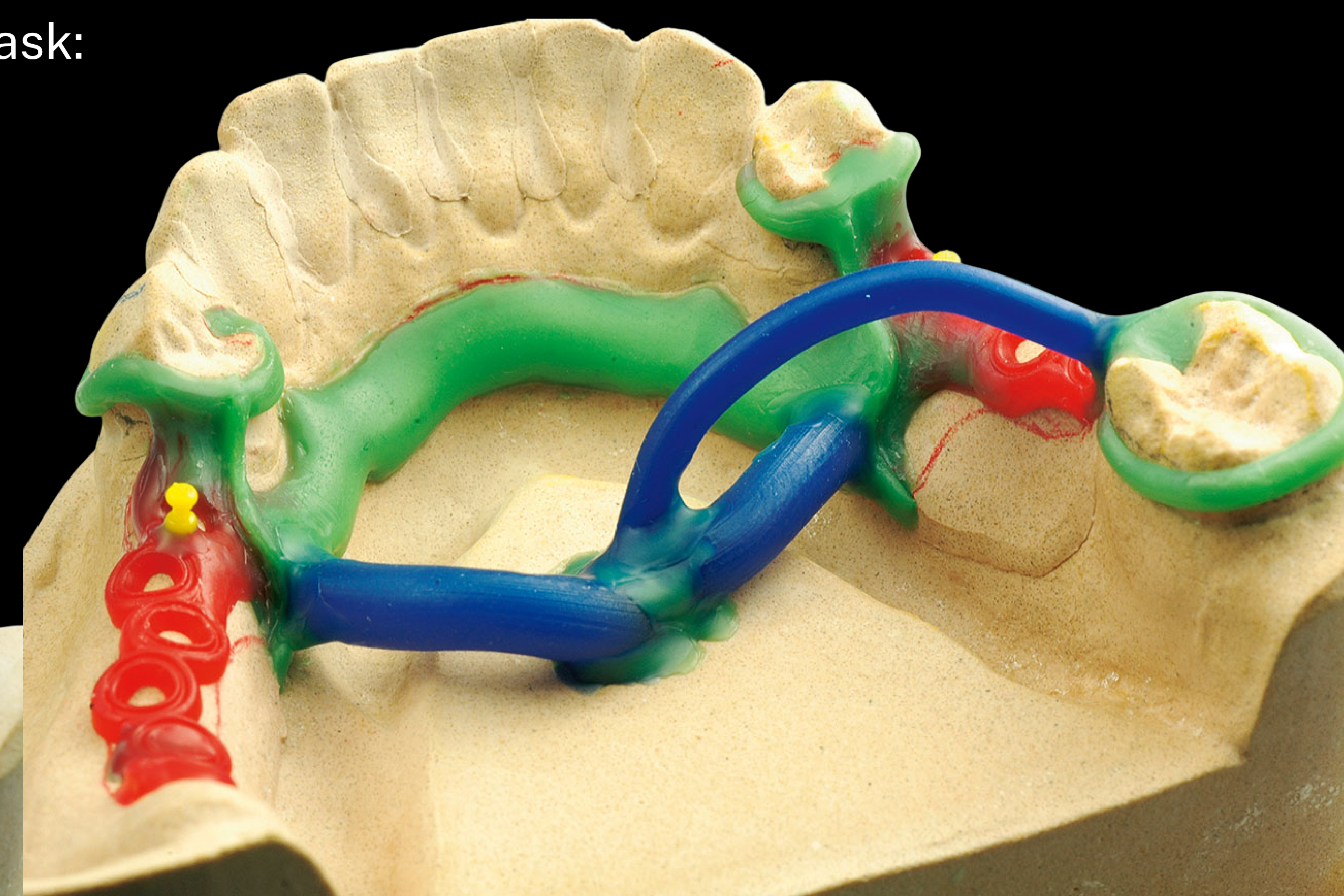
Did we create what we planned?
Check:
- Path of insertion
- Guide planes
- Useful undercuts
- Rest locations
- Framework design
Lecturer — Master Cast Comparison
The master cast should be compared with the preliminary cast after the definitive impression.
- The casts may not survey identically because they cannot always be positioned at exactly the same angle.
- Comparison helps distinguish surveying differences, insufficient preparation, and changes in the definitive cast.
 |  |
Framework
Prove the Framework43
Do not add wax yet.
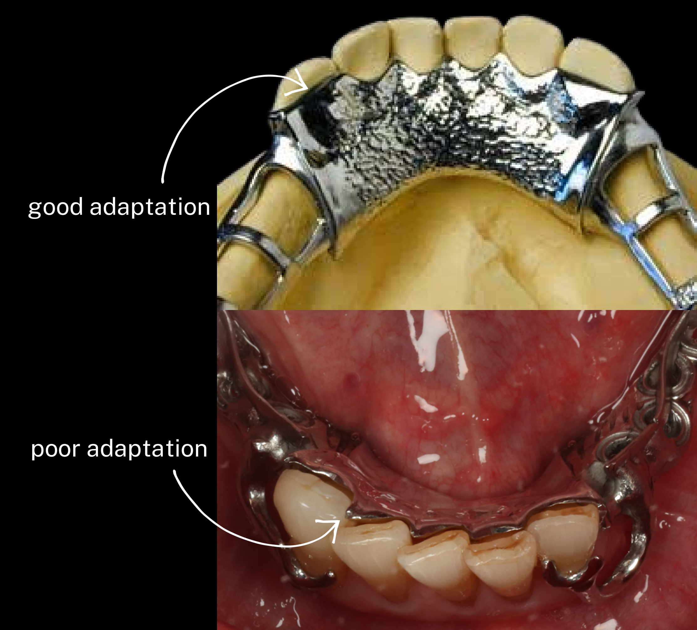
Start on the Master Model — Check
- Seating — full adaptation
- Support — rest contact
- Stability — no rocking
- Retention — clasp engagement
- Function — no interference
Poor adaptation vs good adaptation.
If It Does Not Seat, Do Not Force It44
Find the interference → possible sources:
- Tooth interference
- Guide-plane discrepancy
- Rest interference
- Connector interference
- Distorted framework
- Incorrect path
Lecturer — Framework Seating Problems
If the framework fits the master model but not the mouth, the problem may relate to the impression or the patient’s teeth rather than the laboratory framework.
- Fit checker or occlusal spray can help identify the area preventing seating.
- Sending the same model back for a remake will not correct an inaccurate impression.
- A substantial discrepancy may require a new impression and new framework.

What Can Be Adjusted?45
Possible examples:
- Minor clasp adjustment
- Very limited rest adjustment
- Acrylic component adjustment
Lecturer — Framework Adjustments
Framework adjustments require caution because components may be thin, and excessive adjustment may weaken or fracture the framework.
- Clasp adjustment is not always the solution.
- Add-on components should not be adjusted casually.
- Framework adjustment should involve the supervisor.
Major discrepancy ≠ more grinding → remake framework
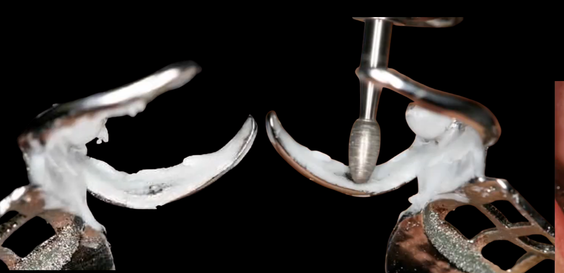
Framework With or Without MMR
Framework Fits, What Is Next?46
Can we safely save a visit?
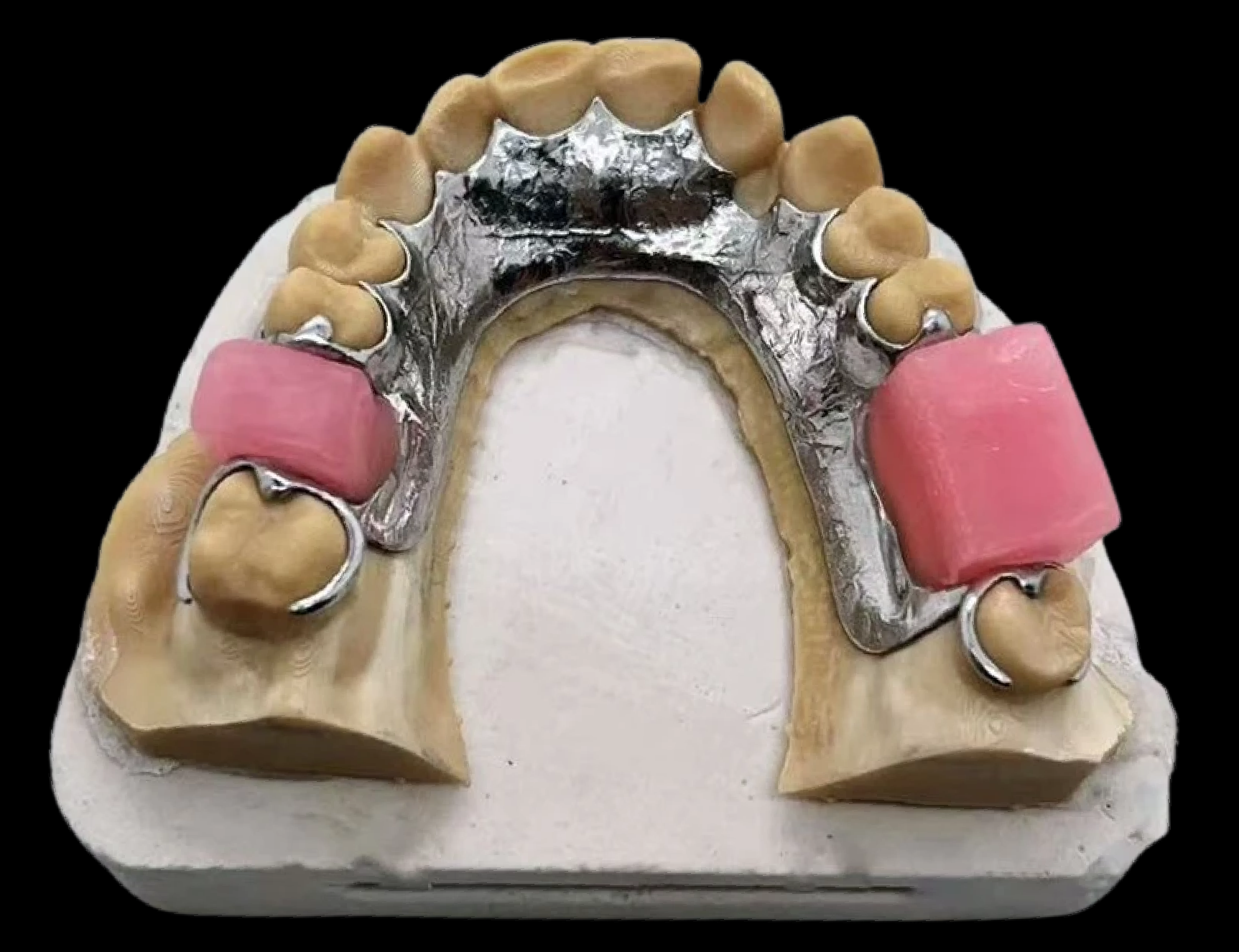
Option 1: Send to Lab
Send to lab → Lab adds rim → Patient returns → Record MMR
When to Choose This Option
- Unstable rim
- Major VDO change
- Complex jaw relationship
- Uncertain tooth position
- Inadequate time / skill to make a reliable record
Can we safely save a visit?
Send to lab → Lab adds rim → Patient returns → Record MMR
- A laboratory-made rim is particularly useful when the edentulous space is extensive, the vertical dimension is being increased, or natural teeth do not provide stable contacts
Option 2: Adapt Rim Chairside47
Adapt rim chairside → Record MMR today
- Save appointment
- Save lab fee
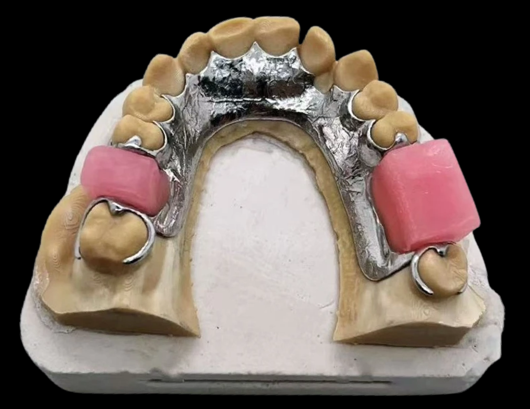
How to Build the Rim Chairside?48
Warm → Adapt → Support → Shape → Re-seat
Lecturer — Chairside Wax Rim
When adapting a wax rim chairside, avoid excess wax beneath the framework and prevent tipping or movement.
- Shape the rim to follow the planned tooth position and curvature of the arch.
- Form the labial contour when anterior tooth position is important.
- The wax rim acts as a blueprint for the tooth arrangement.
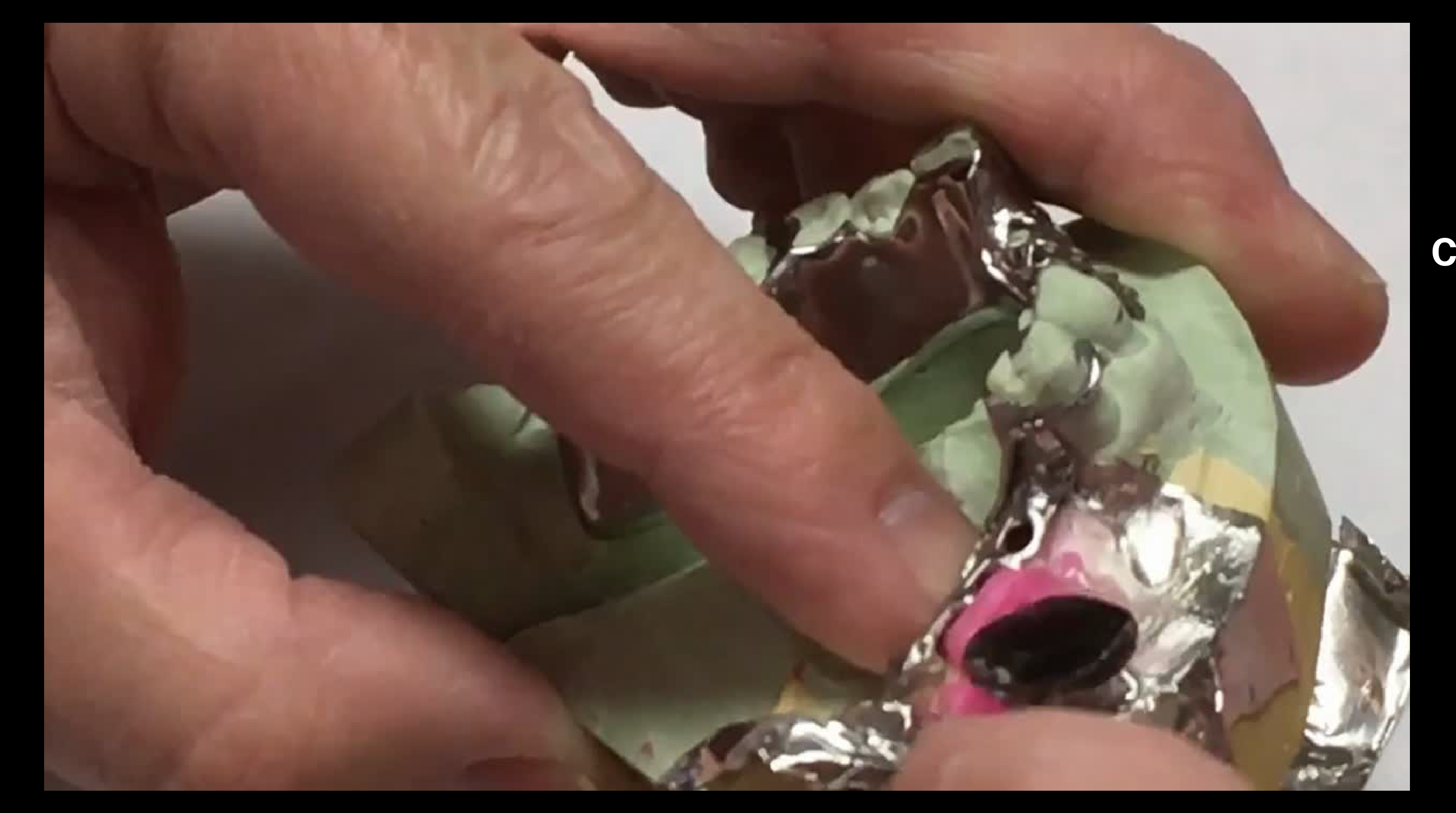
Communicate
-
Tooth position
-
Labial support
-
Occlusal plane
-
Overjet
-
Overbite
-
Arch form
-
Smile line, canine line, midline, tooth size and shape, tooth shade, and the intended vertical dimension
Tooth Try-In: What Are You Assessing?49
Assess:
- Tooth position
- Aesthetics
- Phonetics
- Occlusion
- Retention and stability
- VDO (where relevant)
- Patient acceptance
Co-Cr Insert
Insert50
Framework discrepancy? → Stop + re-assess for remake
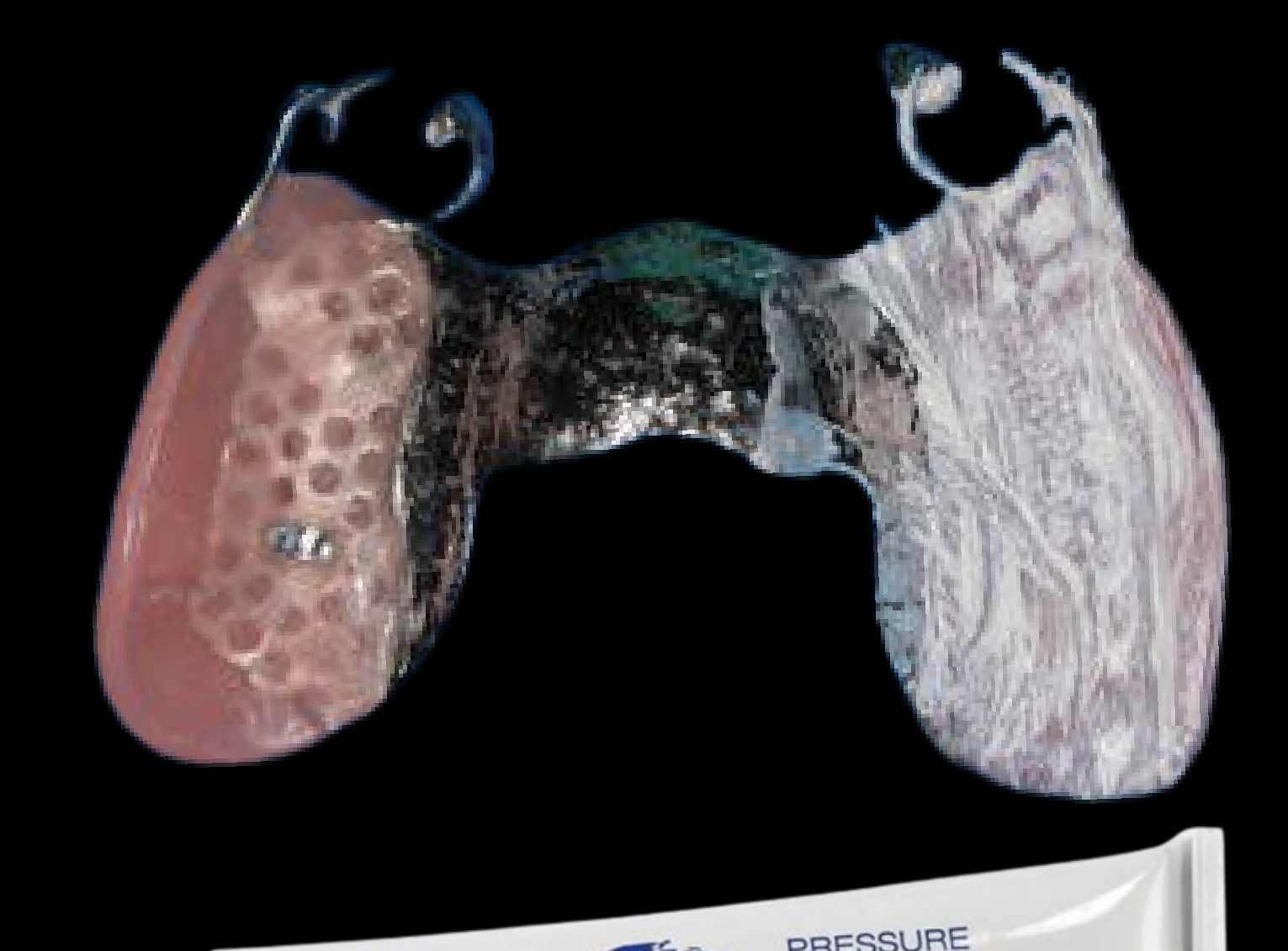
Assess
- Seating — full adaptation
- Support — rest contact
- Stability — no rocking
- Retention — clasp engagement
- Occlusion — no interference
- Tissues — no impingement
- Insertion — correct path
- Removal — patient capable
Adjust acrylic / occlusion as indicated.
Lecturer — Processing Discrepancy
The acrylic may shrink or change during processing, creating a discrepancy even when the framework and tooth try-in were previously satisfactory.
- Assess the acrylic first using pressure-indicating paste or fit checker.
- Confirm framework seating, check occlusion, and adjust conservatively.
- Check the prognosis and suitability of the remaining teeth
- Re-survey the master cast before framework fabrication
- Check indirect retention, prosthetic space, interferences, and occlusal clearance
- Consider whether a new impression is needed if the framework does not fit
- Decide whether a laboratory-made or chairside rim is appropriate
- Confirm tooth position, aesthetics, phonetics, occlusion, vertical dimension, support, stability, and retention
Lecturer — Workflow Planning
These checklists are learning aids for the first several cases, until the workflow becomes familiar.
- Plan from the final treatment objective backwards and understand why each record or impression is being taken.
- Communicate clearly with the laboratory and assess models, impressions, articulations, and frameworks rather than accepting them automatically.
- Consider the patient’s prognosis, expectations, time, and cost to help reduce remakes, errors, and unnecessary adjustments.
Summary and Clinical Checklists
Acrylic RPD — Clinical Stages51
- Primary impression
- Special tray
- Definitive impression
- MMR
- Tooth try-in
- Insert
Co-Cr RPD — Clinical Stages
- Primary impression
- Preliminary articulation
- Preliminary try-in
- Survey + design
- Special tray
- Mouth prep
- Definitive impression
- Framework
- MMR
- Tooth try-in
- Insert
Acrylic RPD — Clinical Checklist52
1. Primary Impression
- Alginate + suitable stock tray
- Accept only if relevant teeth and saddles are captured
- Decide: special tray / secondary impression?
- Lab instructions:
- Final impression material:
- Perforations
- Spacer requirement:
- Tissue stops
2. Special Tray
- Assess on the model
- Check gross extension, seating, sharp edges and interference
- Trim → smooth → reassess
- Border mould needed
3. Definitive Impression
- Adhesive
- Identify and block undercuts
- Check extension, defects, distortion and safety
- Lab instructions:
- Please pour impressions
- Can casts articulate predictably?
- If not: fabricate hard record base / rim
- Clasp positions
4. MMR
- Record a repeatable jaw relationship
- Same CD MMR principles
- Lab instructions:
- Setup teeth on the same hard base
- Tooth shape:
- Shade:
5. Try-in
- Essential for multiple teeth, aesthetics or occlusal uncertainty
- Direct finish may suit small bounded saddles
- Assess aesthetics, phonetics, occlusion and VDO where relevant
- Document patient approval
- Lab instructions:
- Any changes:
- Please process
6. Insert
- Identify path of insertion: do not force
- If not seated: adjust
- Rigid acrylic interference
- Clasp retention
- Assess extensions and pressure areas
- Patient inserts/removes; hygiene and review arranged
 |  |
 |
Co-Cr RPD — Clinical Checklist (Part 1 of 2)
1. Primary Impression
- Alginate + suitable stock tray
- Accept only if relevant teeth and saddles are captured
- Decide if diagnostic base and rim is required for preliminary articulation
- Lab instructions:
- Pour primary impressions
- Fabricate diagnostic base and rim; then clinically proceed with diagnostic MMR, then ask lab to articulate
- Articulate models using bite reg if diagnostic base and rim are not needed
- Preliminary survey
2. Special Tray
- Assess on the model
- Check gross extension, seating, sharp edges and interference
- Trim → smooth → reassess
- Border mould if needed
3. Preliminary Articulation / Preliminary Try-in
- Assess interarch relationship and prosthetic space
- Ask for preliminary tooth setup in complex cases
- Lab instructions:
- Any changes:
- Please process
4. Survey + Design
- Survey diagnostic cast: path, undercuts and interferences
- Plan support, bracing, reciprocation and retention
- Design connector, rests, clasps and bases
- Identify required mouth preparations
- Supervisor approval and design documented
- Lab instructions:
- Fabricate special tray (PVS/iron perforated with 3 mm spacer and tissue stops)
5. Framework Try-in
- Check on master cast
- Assess seating, support, stability and function
- If not seated: do not force — identify why and ask
- Lab instructions:
- Please pour secondary
- Fabricate metal frame to the design
6. Syringe / Definitive Impression
- Check gross extension, seating, sharp edges and interference
- Trim → smooth → reassess
- Border mould if needed
- Adhesive
- Verify preparations before:
- Light body on rests, guide plate-contact areas
- Check extension, defects
- Framework still seats and rim is stable
- Record a repeatable jaw relationship
- Same CD MMR principles
- Lab instructions:
- Setup teeth
- Tooth shape:
- Shade:
- Attach full face photos with rim in mouth: smiling and at rest
7. MMR
- Only after verified framework
- Can it be recorded today with a chairside rim?
- If yes: warm, adapt, support, shape and re-seat
- Framework still seats and rim is stable
- Record a repeatable jaw relationship
- Lab instructions:
- Same CD MMR principles
- Setup teeth
- Tooth shape:
- Shade:
- Attach full face photos with rim in mouth: smiling and at rest
8. Insert
-
Identify path of insertion: do not force
-
If not seated: adjust
- First interference (PIP, occlusal spray, Fit Checker)
-
Assess extensions and pressure areas
-
Patient inserts/removes; hygiene and review arranged
-
Identify the first contact and adjust conservatively
Closing53
THANK YOU
- AH — Ahmad Hendawi
- ST — Sheryl Teo
Prosthodontics
 |  |
 |
Clinical Cases
Case: OPG Presentation for Removable Partial Denture
Question
Scenario: A patient presents to the clinic with missing teeth, and an OPG is shown to the students.
What’s shown: An OPG of a patient with missing teeth.
Consider: Beyond simply identifying the edentulous spaces and missing teeth, what factors must be evaluated to decide between an acrylic or chrome denture?
Answer
Observations:
- Periodontal prognosis (mobility, stage, grade)
- Restorability and remaining tooth structure
- Occlusal anatomical function
- Patient-related factors and previous prosthesis history
Reasoning: The decision for acrylic versus chrome is not based solely on Kennedy classification or missing teeth. The clinician must evaluate the overall condition of the mouth, including whether teeth are useful for the denture design, the cause of mobility, and what the patient previously tolerated, to ensure the new design improves upon the previous one.
Takeaway: Look beyond the edentulous spaces and evaluate the periodontal prognosis, restorability, occlusal function, and previous prosthesis history to guide the decision between acrylic and cobalt chrome.
Case: Erratic Tooth Impeding Denture Design
Question
Scenario: A patient has a super erratic tooth that is getting in the way of the occlusal scheme.
What’s shown: A sound, non-mobile tooth that does not need restoration but is impeding the balanced denture design.
Consider: Should this tooth be kept or extracted?
Answer
Observations:
- The tooth is sound, not mobile, and doesn’t need restoration.
- It is impeding the creation of a balanced denture.
Reasoning: Even if a tooth is restorable and has a good prognosis, if it doesn’t fit the treatment plan or impedes a balanced denture, there is no point in keeping it. The focus should be on whether the tooth is useful for the overall prosthesis design.
Takeaway: A tooth’s usefulness for the overall prosthesis design is more important than just its individual restorability or prognosis.
Case: Bounded Saddle Replacing Two Teeth
Question
Scenario: A patient needs a denture replacing just two teeth in a bounded saddle.
What’s shown: A bounded edentulous space replacing two teeth.
Consider: Is a special tray and secondary impression needed for this case?
Answer
Observations:
- The space is a bounded saddle.
- Only two teeth are being replaced.
Reasoning: For a bounded saddle, there is no need to extend the acrylic flange into the full vestibule for tissue support. If the primary alginate impression is good, it can be used as the final impression without a special tray or secondary impression.
Takeaway: Bounded saddles replacing a few teeth may not require a special tray or secondary impression if the primary impression captures the necessary anatomy.
Case: Rural Patient Driving Four Hours
Question
Scenario: A patient in a rural area has driven four hours to the clinic and wants to minimize chair time and appointments.
What’s shown: A clinical scenario of a patient with limited availability and long travel distance.
Consider: How can the impression workflow be modified to save the patient an extra trip?
Answer
Observations:
- The patient has a long travel distance and limited time.
- A standard multi-step special tray workflow would require multiple visits.
Reasoning: The clinician can customize the primary stock tray impression (e.g., adding putty or border molding directly) to capture the necessary extensions in a single visit, skipping the special tray step to save the patient time and travel.
Takeaway: Patient circumstances, such as travel distance and time constraints, can justify modifying the standard impression workflow to save appointments.
Case: Stuck Polyether Impression
Question
Scenario: A polyether impression gets stuck in the patient’s mouth due to undercuts.
What’s shown: A clinical scenario where a rigid impression material locks into undercuts.
Consider: What is the immediate management when a polyether impression is stuck?
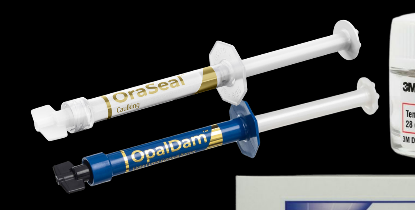
Answer
Observations:
- Polyether is extremely hard when set.
- The impression is locked in undercuts and cannot be removed.
Reasoning: The clinician must section the special tray and cut the impression material intraorally to release the undercuts. This is a risky procedure that can tear soft tissue, emphasizing the need to block out undercuts before taking a polyether impression.
Takeaway: Always block out undercuts before using polyether to prevent the impression from locking and requiring intraoral sectioning.
Case: Assessing Impression Deficiencies
Question
Scenario: A student presents an impression with a drag or deficiency and asks if it is acceptable to proceed.
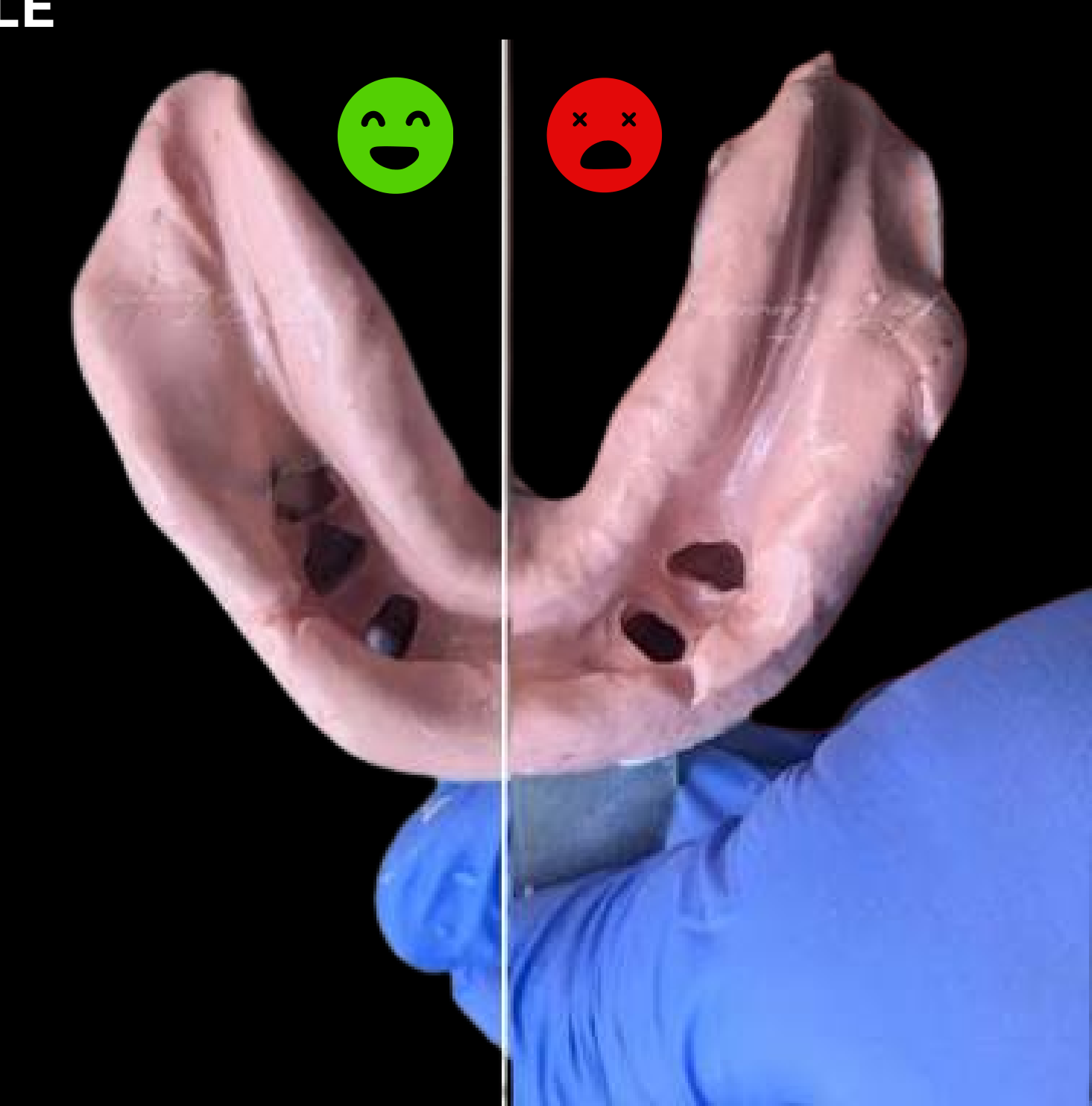
What’s shown: An impression with a drag in the buccal area versus a deficiency in the retromolar pad area.
Consider: How does the location of an impression deficiency affect the decision to proceed?
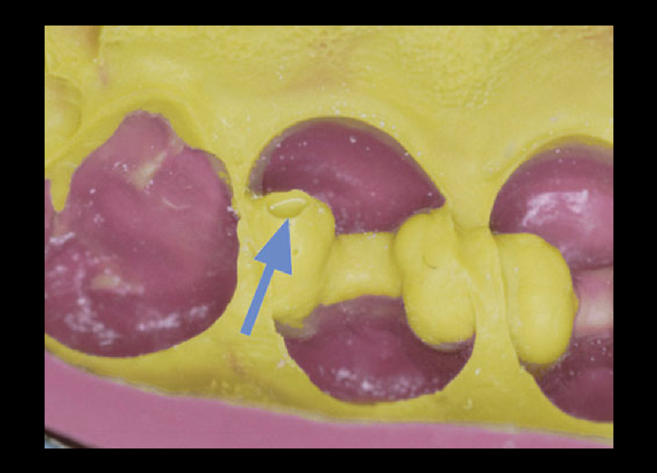
Answer
Observations:
- A drag in the buccal area where no denture extension is planned.
- A deficiency in the retromolar pad or buccal shelf area.
Reasoning: A drag in an area not relevant to the denture design (like the buccal vestibule where the denture won’t extend) is acceptable. However, a deficiency in a critical support area like the retromolar pad means the impression failed its purpose and must be retaken.
Takeaway: Evaluate impression deficiencies based on their relevance to the planned denture design and tissue support areas.
Case: Missing 15, 16, 17 and Need for MMR
Question
Scenario: A patient presents missing teeth 15, 16, and 17, with all other teeth present.
What’s shown: A dentition with a unilateral free-end saddle (missing 15, 16, 17).
Consider: Does this patient need a Maxillomandibular Relationship (MMR) record?
Answer
Observations:
- The patient is missing 15, 16, and 17.
- The rest of the dentition is present.
Reasoning: While there are posterior occlusal stops on the other side, free-end saddles (Kennedy Class 1 and 2) can cause models to tilt during articulation. The lab technician needs stable models, so an MMR is recommended to ensure accurate articulation and prevent rocking.
Takeaway: Even with existing occlusal stops, free-end saddles require an MMR to prevent model tilting and ensure accurate articulation.
Case: Modifying the Missing Molar Scenario for MMR
Question
Scenario: The lecturer modifies a previous scenario: instead of missing 15, 16, 17, the patient has a first molar present but is missing the second molar, with stable occlusal stops.
What’s shown: A dentition with a missing second molar but stable posterior occlusion.
Consider: Does this patient need an MMR?
Answer
Observations:
- The patient has stable occlusal stops (e.g., first molars occluding).
- There is no free-end saddle.
Reasoning: With stable occlusal stops and a bounded or tooth-supported situation (like a Kennedy Class 3 with tripod contact), the models can be stabilized without an MMR. The technician can articulate the models predictably using a bite registration.
Takeaway: Stable occlusal stops and the absence of free-end saddles may allow for articulation without a formal MMR, provided there is tripod contact.
Case: Kennedy Class 3 Model and Tripod Contact
Question
Scenario: The lecturer passes around a Kennedy Class 3 model to demonstrate articulation.
What’s shown: A Kennedy Class 3 model with posterior and anterior teeth present.
Consider: How can you determine if an MMR is needed based on model articulation?
Answer
Observations:
- The model has posterior teeth and anterior teeth.
- It forms a tripod contact (two posteriors, one anterior).
Reasoning: If there is tripod contact, the models can be stabilized on the articulator without rocking. Therefore, a bite registration is sufficient, and a full MMR with base and rims is not strictly necessary.
Takeaway: Tripod contact (two posteriors and one anterior) provides sufficient stability for model articulation without needing a full MMR.
Case: Replacing a Single Central Incisor
Question
Scenario: A patient needs a denture replacing only a single central incisor (tooth 11).
What’s shown: A partial denture design replacing one anterior tooth with stable occlusion and good articulation.
Consider: Is a tooth try-in appointment necessary?
Answer
Observations:
- Only one tooth (tooth 11) is being replaced.
- Occlusal contacts are stable, and a bite registration was taken.
Reasoning: If the occlusion is stable, the shade is correctly chosen (preferably with a photo), and the articulation is accurate, a tooth try-in can be skipped, and the case can proceed directly to the final denture.
Takeaway: A tooth try-in may be omitted for simple, single-tooth replacements with stable occlusion and clear aesthetic instructions.
Case: Framework Try-in with Fit Checker
Question
Scenario: A cobalt chrome framework is tried in the patient’s mouth but doesn’t sit fully.
What’s shown: A framework that is not fully seated, assessed using fit checker or occlusal spray.
Consider: How do you identify and manage the interference preventing the framework from seating?
Answer
Observations:
- Fit checker shows the material rubbing off only in one specific area, indicating a premature contact.
- Occlusal spray shows contact only in that localized area.
Reasoning: The localized rub-through indicates an interference. The clinician should make minimal adjustments to that specific area on the framework (or acrylic) and reseat, rather than adjusting the clasps or forcing it in.
Takeaway: Use fit checker or occlusal spray to localize interferences during a framework try-in, and make minimal, targeted adjustments.
Case: First Visit with No Occlusal Stops
Question
Scenario: A patient presents for their first visit with upper and lower alginate impressions, but has no occlusal stops.
What’s shown: A patient with missing teeth and no stable occlusal contacts.
Consider: What is the workflow for establishing the vertical dimension in this scenario?
Answer
Observations:
- The patient has no occlusal stops.
- Primary alginate impressions are taken.
Reasoning: The clinician should request diagnostic base and rims from the lab. The patient is then treated similarly to a complete denture patient to determine the desired vertical dimension and freeway space. Once the diagnostic MMR is taken, the clinician must stick to that vertical dimension throughout the treatment.
Takeaway: When there are no occlusal stops, use diagnostic base and rims to establish and lock in the vertical dimension early in the treatment plan.
Case: RPD with Surveyed Crown
Question
Scenario: A patient needs an acrylic RPD and a surveyed crown on a tooth that requires an increase in vertical dimension.
What’s shown: A treatment plan combining a surveyed crown and a removable partial denture.
Consider: How should the vertical dimension and crown design be managed before preparing the tooth?
Answer
Observations:
- The patient needs an RPD and a surveyed crown.
- The vertical dimension needs to be increased.
Reasoning: A diagnostic MMR must be taken first to decide the new vertical dimension. The crown is then waxed up to the new vertical dimension before preparation. This ensures the tooth is prepared correctly for the final vertical dimension, avoiding excessive reduction or inadequate space for the crown and denture.
Takeaway: Always perform a diagnostic MMR to establish the final vertical dimension before preparing a tooth for a surveyed crown in an RPD case.
Case: Tooth 37 with a Large Crack
Question
Scenario: A student presents a case where tooth 37 has a large crack, and they are considering a survey crown for an RPD.
What’s shown: A cracked tooth (37) being considered as an abutment for a survey crown and RPD.
Consider: Should the cracked tooth be crowned, and what are the risks?
Answer
Observations:
- Tooth 37 has a large crack.
- It is being considered for a survey crown to serve as an abutment.
Reasoning: Crowning the tooth can embrace it and reduce the potential for crack propagation. However, placing an occlusal rest on a cracked tooth increases the risk of failure. The clinician must warn the patient about this risk and obtain informed consent, ensuring the design minimizes lateral forces.
Takeaway: A survey crown can protect a cracked tooth, but placing a rest on it increases the risk of failure; the patient must be warned and informed consent obtained.
Footnotes
-
Original PDF page 1: L5 RPD Hindawi, p.1 ↩
-
Original PDF page 2: L5 RPD Hindawi, p.2 ↩
-
Original PDF page 3: L5 RPD Hindawi, p.3 ↩
-
Original PDF page 4: L5 RPD Hindawi, p.4 ↩
-
Original PDF page 5: L5 RPD Hindawi, p.5 ↩
-
Original PDF page 6: L5 RPD Hindawi, p.6 ↩
-
Original PDF page 7: L5 RPD Hindawi, p.7 ↩
-
Original PDF page 8: L5 RPD Hindawi, p.8 ↩
-
Original PDF page 9: L5 RPD Hindawi, p.9 ↩
-
Original PDF page 10: L5 RPD Hindawi, p.10 ↩
-
Original PDF page 14: L5 RPD Hindawi, p.14 ↩
-
Original PDF page 15: L5 RPD Hindawi, p.15 ↩
-
Original PDF page 17: L5 RPD Hindawi, p.17 ↩
-
Original PDF page 16: L5 RPD Hindawi, p.16 ↩
-
Original PDF page 18: L5 RPD Hindawi, p.18 ↩
-
Original PDF page 19: L5 RPD Hindawi, p.19 ↩
-
Original PDF page 20: L5 RPD Hindawi, p.20 ↩
-
Original PDF page 21: L5 RPD Hindawi, p.21 ↩
-
Original PDF page 22: L5 RPD Hindawi, p.22 ↩
-
Original PDF page 23: L5 RPD Hindawi, p.23 ↩
-
Original PDF page 27: L5 RPD Hindawi, p.27 ↩
-
Original PDF page 24: L5 RPD Hindawi, p.24 ↩
-
Original PDF page 25: L5 RPD Hindawi, p.25 ↩
-
Original PDF page 26: L5 RPD Hindawi, p.26 ↩
-
Original PDF page 29: L5 RPD Hindawi, p.29 ↩
-
Original PDF page 30: L5 RPD Hindawi, p.30 ↩
-
Original PDF page 31: L5 RPD Hindawi, p.31 ↩
-
Original PDF page 32: L5 RPD Hindawi, p.32 ↩
-
Original PDF page 37: L5 RPD Hindawi, p.37 ↩
-
Original PDF page 40: L5 RPD Hindawi, p.40 ↩
-
Original PDF page 35: L5 RPD Hindawi, p.35 ↩
-
Original PDF page 36: L5 RPD Hindawi, p.36 ↩
-
Original PDF page 38: L5 RPD Hindawi, p.38 ↩
-
Original PDF page 39: L5 RPD Hindawi, p.39 ↩
-
Original PDF page 41: L5 RPD Hindawi, p.41 ↩
-
Original PDF page 42: L5 RPD Hindawi, p.42 ↩
-
Original PDF page 43: L5 RPD Hindawi, p.43 ↩
-
Original PDF page 44: L5 RPD Hindawi, p.44 ↩
-
Original PDF page 45: L5 RPD Hindawi, p.45 ↩
-
Original PDF page 47: L5 RPD Hindawi, p.47 ↩
-
Original PDF page 48: L5 RPD Hindawi, p.48 ↩
-
Original PDF page 49: L5 RPD Hindawi, p.49 ↩
-
Original PDF page 50: L5 RPD Hindawi, p.50 ↩
-
Original PDF page 51: L5 RPD Hindawi, p.51 ↩
-
Original PDF page 52: L5 RPD Hindawi, p.52 ↩
-
Original PDF page 53: L5 RPD Hindawi, p.53 ↩
-
Original PDF page 54: L5 RPD Hindawi, p.54 ↩
-
Original PDF page 55: L5 RPD Hindawi, p.55 ↩
-
Original PDF page 56: L5 RPD Hindawi, p.56 ↩
-
Original PDF page 57: L5 RPD Hindawi, p.57 ↩
-
Original PDF page 58: L5 RPD Hindawi, p.58 ↩
-
Original PDF page 59: L5 RPD Hindawi, p.59 ↩
-
Original PDF page 60: L5 RPD Hindawi, p.60 ↩