Biomechanics and Preclinical Orthodontics
Orthodontic Seminar
Seminar Overview12
-
This is a review session for Level 3A and 3B students.
-
The material covered has been introduced previously; the session consolidates key concepts.
-
Morning schedule: two lectures (this review).
-
Afternoon schedule: three lectures covering orthodontic devices, special needs patients, and retention.
-
All slides from today’s lectures will be posted online and remain available until tomorrow.
-
Part 1. Orthodontic Diagnosis & Treatment Planning
-
Part 2. Biologic Response to Orthodontic Force
-
Part 3. Mechanical Principles in Controlling Orthodontic Force
-
Part 4. Orthodontic Anchorage and Controlled Tooth Movement
Orthodontic Seminar
- Part 1. Orthodontic Diagnosis & Treatment Planning
- Part 2. Biologic Response to Orthodontic Force
- Part 3. Mechanical Principles in Controlling Orthodontic Force
- Part 4. Orthodontic Anchorage and Controlled Tooth Movement
Orthodontic Diagnosis and Treatment Planning
Part 1. Orthodontic Diagnosis & Treatment Planning
Be sure that you are able to3
- Recognize and evaluate skeletal and dental relationships in all three planes of space.
- Recognize and quantify the patient’s arch length status.
- Evaluate the skeletal and arch length considerations, interactions and appropriateness of treatment or non-treatment.
- Recommend treatment or referral of specific problems based upon case evaluation.
Skeletal and Dental Evaluation
- Recognize and evaluate skeletal and dental relationships in all three planes of space.
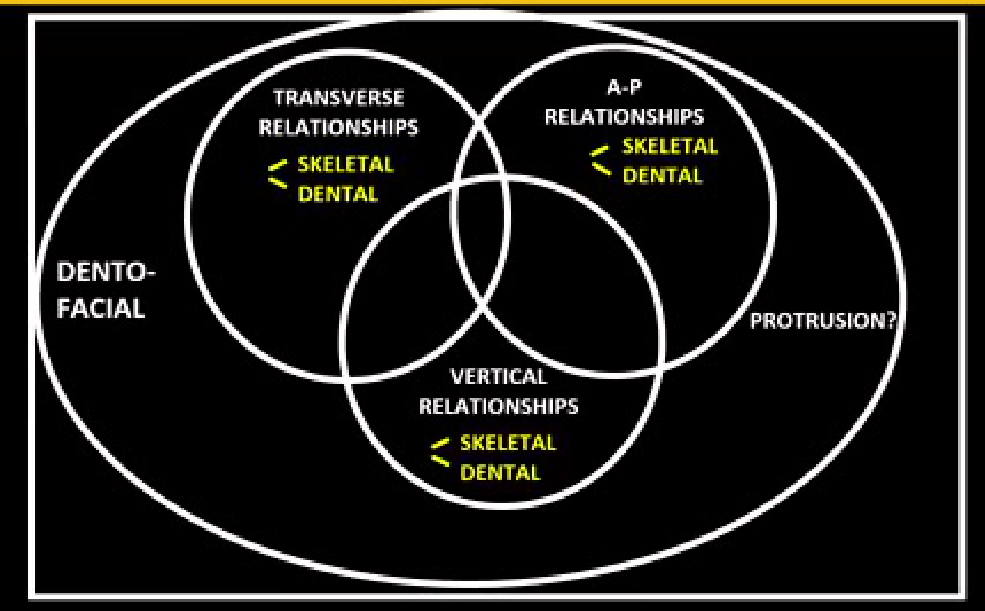
Ackerman-Proffit Classification4
- Described as a more genetic/structured way to proceed with classification of malocclusion (referenced to the Proffit textbook).
- The patient is evaluated considering all three planes of space, reducing the chance of overlooking important findings and allowing a more consistent diagnostic approach.
- The goal is to make a differential diagnosis between skeletal and dental problems.
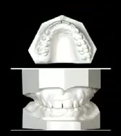
- Analysis is performed using study models/casts:
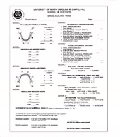
- In mixed dentition, space prediction is used to estimate space available for eruption of permanent teeth.
- Arch shape is analyzed to detect transverse discrepancies between the upper and lower arches.
- Vertical problems are assessed, including excessive overbite and open bite.
Alignment and Asymmetry
Alignment/Asymmetry5
 |  |
Esthetic Impact of Malocclusion
- Esthetic impact is largely determined by the soft tissue response (lips) overlying the teeth.
- Lack of space or excessive proclination of incisors changes lip behavior and profile (emphasized during cephalometric analysis).
- Hyper-divergent patients have an increased mandibular angle, which reflects on lower facial height.
Annie C. 21Y 6M Initial
Spatial Relationships in Orthodontics
Transverse Relationships
Transverse Relationships6
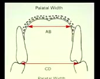
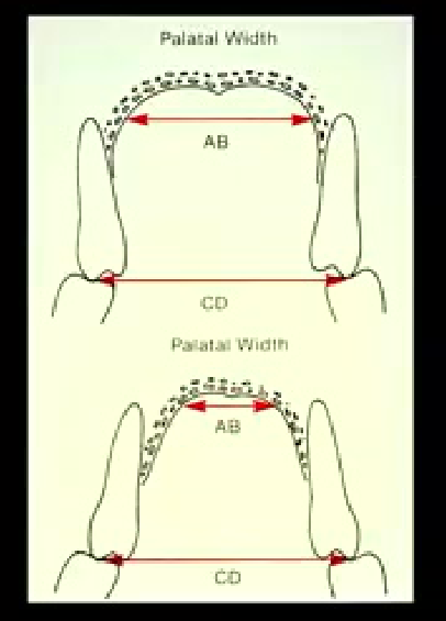
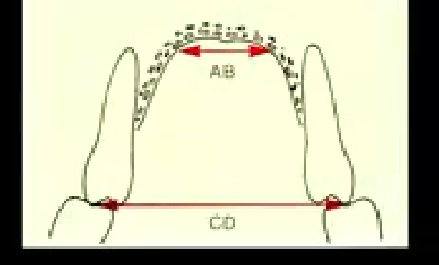
- Palatal width is assessed on the casts.
- Used to differentiate skeletal vs. dental crossbite:
- Dental crossbite: palatal width is normal (AB distance appears normal); upper molars may be excessively lingually tilted due to an altered eruption pathway.
- Skeletal crossbite: palatal width is narrow (athresic upper arch); upper molars may show buccal tilt as compensation, but the underlying problem remains skeletal.
- In severe skeletal crossbite, the upper arch sits completely lingual to the lower arch, and compensatory tilting of the upper molars is not possible.
6
 |  |
 |
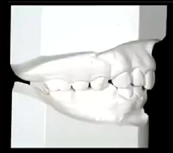
Anterior-Posterior Relationships
- Assessed via profile analysis:
- Skeletal Class 1: balanced profile.
- Class 2: convex profile.
- Class 3: concave profile.
A-P Relationships
- Class I skeletal pattern
- Class II skeletal pattern
- Class III skeletal pattern
7
Vertical Relationships
Anne C. 12Y 6M Initial 8
Biologic Response to Orthodontic Force7
Be sure that you are able to:
- Describe the histologic/cellular/vascular response of the supporting structures to force applied to teeth.
- Discuss the role of biologic electricity in maintenance and turnover of alveolar bone.
- Describe the relationship of orthodontic force levels to anchorage.
Histologic and Cellular Responses8
- Describe the histologic/cellular/vascular response of the supporting structures to force applied to teeth.
Light Continuous Pressure Mechanics91011
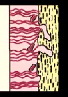
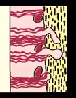
Time Sequence - Light Continuous Pressure
- Milliseconds - Fluid pressure up, piezo-electric effect
- Seconds - Fluid pressure balanced
- Minutes - Blood flow affected
- Hours - Cellular differentiation begins
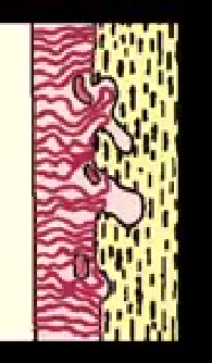
- Days - Apposition/resorption, tooth movement
- The response to orthodontic force is time-dependent
- Milliseconds (very early): fluid pressure increases because there is no time for the fluid to drain — described with a “water pillow” analogy (rapid compression raises internal pressure before the fluid can escape)
- This pressure is transferred to the alveolar bone, where loading changes the crystalline structure of the bone
- Minutes: if vessels are completely shut off (100%), the PDL cannot receive nutrients and necrosis occurs — reorganized through hyalinization, but delays tooth movement
- Bone turnover typically occurs within 6–7 days
- Prostaglandins and cytokines mediate cell-to-cell communication and influence the differentiation of osteoclasts and osteoblasts; the ratio of these cells depends on the amounts of cytokines and prostaglandins released
| Force Against Tooth |
|---|
| Blood Flow Change |
| Mechanical Deformation? |
| Prostaglandin Release |
| --- |
| Stimulus to Form |
| Osteoclasts/Osteoblasts |
| --- |
| Remodelling |
- Describe the histologic/cellular/vascular response of the supporting structures to force applied to teeth.
 |  |
 |  |
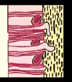
Heavy Pressure and Hyalinization121314
- With heavy pressure, PDL vessels become completely blocked, the PDL is no longer sustainable, and sterile necrosis occurs (no infection, no bacteria — a direct result of blood vessel shut-off)
- This triggers the hyalinization process
- Force must be controlled to prevent sterile necrosis of the PDL
| Heavy Pressure | → | Total shut-off of blood flow | → | Sterile Necrosis = hyalinization |
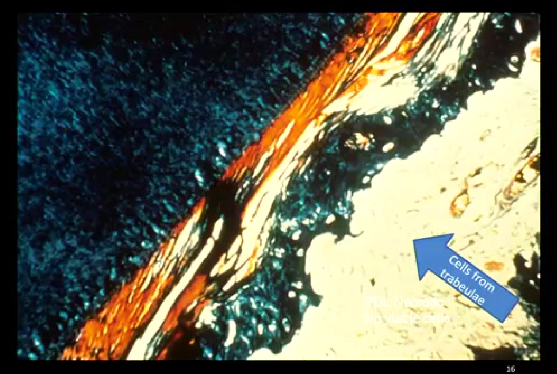
Cells from trabeculae
 |  |
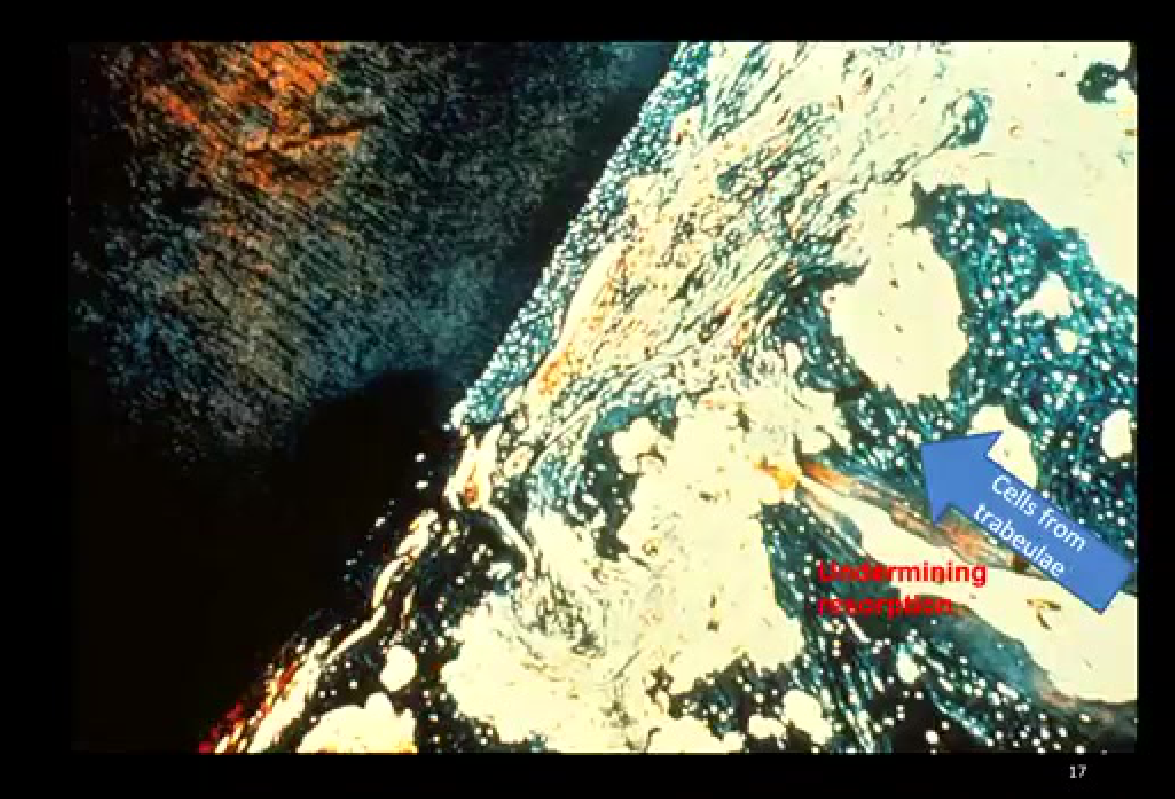
Undermining Resorption15
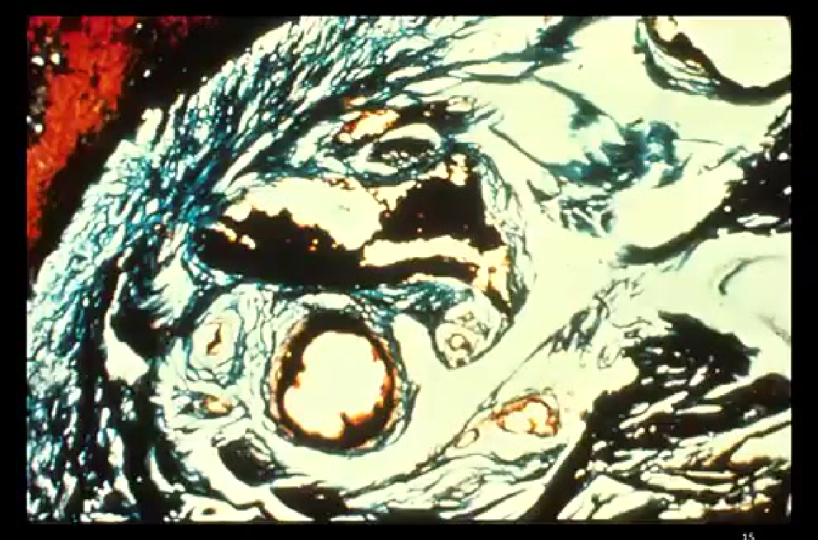
- Histological images (using India ink) show blood vessels shut off under heavy pressure zones
- The PDL is completely compressed, with no viable cells remaining
- Because PDL cells cannot supply the differentiated cells needed for bone turnover, cells must come from the bone itself, which takes more time
- Undermining resorption occurs until the PDL is rebuilt — a process that takes significantly longer and is a problem between orthodontic appointments
Cells from trabeculae
Undermining resorption
Biologic Electricity and Piezoelectric Effect16
The Piezo-Electric Effect
Changing the shape of a crystalline material causes an electrical current flow
- The piezoelectric effect occurs when a millisecond force loads the bone: the crystalline structure changes, causing a reorientation of electrons and generating a very tiny electric current
- This tiny current is sufficient to change the membrane balance and cell differentiation
- The effect occurs in all mineralized bones, not just alveolar bone (e.g., during walking)
Bone loading in microgravity
Astronauts lose bone mass outside gravity because the bone is no longer loaded.
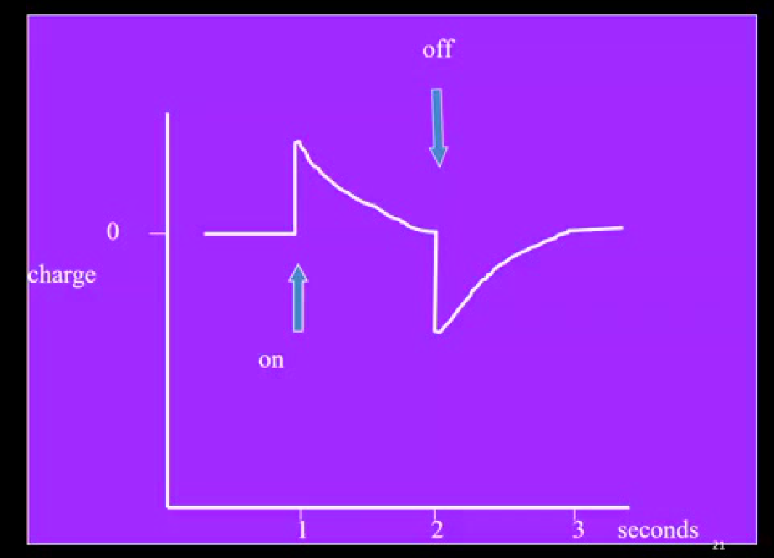
- Charge curve over time:
- At rest (unloaded), the overall charge across the tissue is zero (steady state)
- On loading, the charge increases (positive) because electrons (negatively charged) migrate rapidly — within the first second (millisecond scale)
- The charge then balances over time as some electrons return
- On unloading, the charge drops vertically down, then gradually returns to zero
- The curve is symmetrical — if cut and flipped, it mirrors the opposite region

Bone Mineralization Dynamics17
Handling 3D Bone Mineralization
2. Re-establish established bone mineralization
- IF CB
- -> Trigger PTP/Pt & pCa signals
- -> Stop Mesenchymal Stem Cell (MSC) proliferation
2D X-ray
OSSIFICATION Center (m. M./mm.) + RhGM
- Encloth by bone mineral (Ca2+)
3. Re-establish established bone mineralization (Sustained)
- IF CB
- -> Trigger PTP/Pt & pCa signals
- -> Maintain MSC replication
- -> Maintain mineralization if 1st rate (Crisis avoided)
Figure: Piezoelectricity in bone.
Piezo-Electricity in Bone
Source:
- Bone Mineral
- Collagen
Effect:
- Rhythmic pulses of electric pulses during function (chewing, walking etc)
- Important in order to maintain mineralization
Time Course of Heavy Pressure
Time course of events: Heavy biting pressure
Milliseconds
Fluid incompressible in periodontal ligament
Seconds
Fluid leaking out
Minutes
Fluid gone: Pain
- Pain management: to decrease pain, medication should be prescribed 15 minutes before the appointment — the time required to block the release of prostaglandins
- If medication is given later (within a couple of minutes), there is no time to prevent the initial trigger of pain
Anchorage and Force Level Relationships1819
- Describe the relationship of orthodontic force levels to anchorage.
Relative Anchorage Values of Teeth20
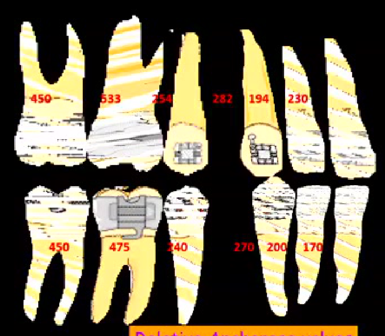
Relative Anchorage values
- Anchorage is defined as everything that opposes tooth movement
- Quantified by numbers reflecting the amount of root surface area within the bone; double-rooted teeth provide more anchorage and more resistance to movement
Premolar extraction case
- Anchorage unit: the 5, 6, and 7 (combined to increase anchorage significantly) - Movement unit: the canine - Expected result: less movement of the anchorage unit, more movement of the canine
Types of Orthodontic Anchorage21
- Simple
- Reciprocal
- Reinforced
- Stationary
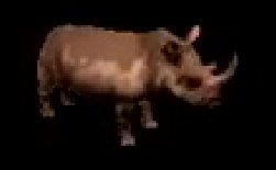
Simple Anchorage22232425
- Occurs when two teeth are connected (e.g., by a power chain or elastic).
- Both teeth are likely to move, but the amount depends on their relative anchorage values.
- Example: a premolar (lower anchorage value) will move more than the molar (6).
- Reciprocal anchorage: when two teeth have very similar anchorage levels and are connected, they move reciprocally (equal and opposite movement).
Stationary Anchorage2627
- Achieved by bending a wire with a loop downwards, so the force passes closer to the center of resistance.
- The anchorage unit moves bodily without tilting.
- Preventing tilting allows for a higher level of movement control because force is applied in a constant way.
- The anchorage unit moves less than it would if the force were not passing through the center of resistance.
 |  |
Force Magnitude and Anchorage Response28
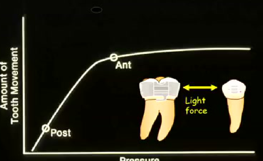
- Light force: sufficient to move the desired teeth (e.g., anterior teeth), but not strong enough to move the anchorage unit (posterior teeth remain stationary) — low pressure on the PDL of the anchorage unit.
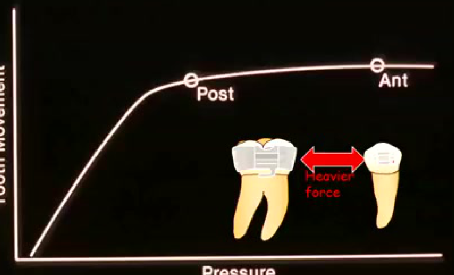
- Heavy force: can shut off blood vessels in the PDL, causing necrosis and a lack of movement for several days (hyalinization). In this case, the heavy force may be more than enough to move the anchorage unit, while the anterior teeth are stalled.
- If uncontrolled, this can disengage a Class 1 relationship, resulting in a Class 2 molar relationship on the upper arch.
- Correcting (retracting/digitalizing) a molar is 10 times more difficult than moving a premolar.
Amount of Tooth Movement
Post
Ant
Heavier force
Pressure
Removable Orthodontic Appliances
- Describe and recognize different types of removable orthodontic appliances in the following categories:
Categories of Removable Appliances29
-
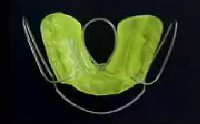
A. Functional appliance — a distinct category.
-
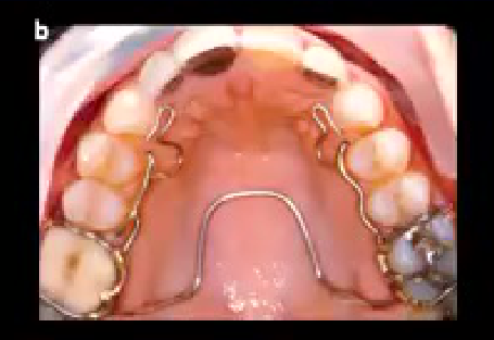
B. Crossbite appliance — an older design (no bends), one of the first devices developed to correct crossbite.
- Contains an omega/looping for dental expansion of the upper arch.
- May have springs for canines occluding edge-to-edge.
- No longer used in the clinic; replaced by quadhelix or W appliance (used in the early treatment clinic on Wednesday afternoons).
-
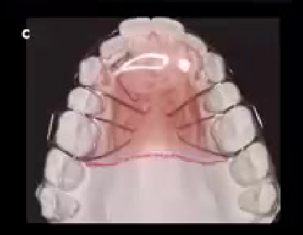
C. Hawley-type removable appliance — has Adams clasps and a spring to correct an anterior crossbite of a lateral incisor.
-
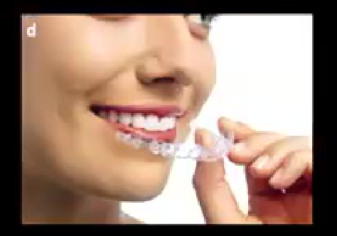
D. Clear aligner — well known to the audience.
-
(a) functional appliances
-
(b) Crozat
-
(c) Hawley type
-
(d) Clear Aligner Therapy
 |  |
 |  |
Active Hawley Appliance Design and Wire Specifications30
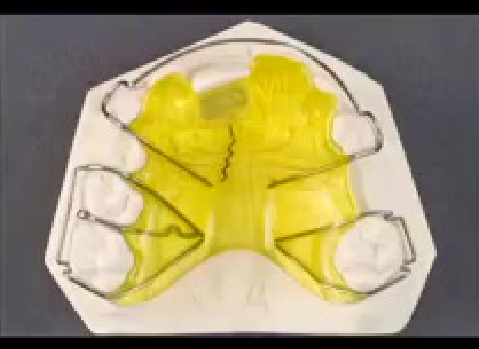
- Example design includes:
- Adams clasp, ball clasp, another Adams clasp, and a Hawley-type clasp.
- A spring underneath the acrylic plate to correct an anterior crossbite of the central incisor.
- Finger spring with two helixes, may be located beneath the acrylic or exposed.
- Activation: the spring is pulled down to the cervical part of the incisor.
- Retention is achieved by insertion of the acrylic plate and by the clasps (Hawley and Adams).
- Spring material: stainless steel (NiTi cannot be bent into this design).
- Wire thickness is reduced to 0.6 or 0.7 mm to increase resilience and provide a more constant force over time.
- Patients are typically seen every second week to reactivate the spring.
- Adams clasp: designed for retention from the six (molar).
- Bow clasp (anterior): designed for retention using the canines (with a band) and the central incisors.
- For increased overjet with flaring incisors, the wire can be activated to retrocline the incisors by closing the springs.
- Important: the retention from the posterior clasps must balance the activation force from the springs, otherwise the plate will come off during function.
-
Describe and make correct appliance designs of the active Hawley type with specific recommendations for these components:
- (a) active
- (b) retention
- (c) connector
- (d) reactive or anchorage
-
Select the correct wire size for active and retentive elements of active Hawley type appliances.
- Lab Bow: 0.7–0.8 mm
- Adams molars: 0.7 mm, premolars: 0.6 mm
- Finger spring guarded: 0.6 mm, unguarded: 0.7 mm
- Ball clasp: 0.7 mm
- C clasp: 0.7 mm
Mechanical Principles in Controlling Orthodontic Force
- Define and explain the biomechanical principles that pertain to orthodontics, specifically the meaning of terms such as “force”, “moment”, “fulcrum”, “center of rotation”, and “anchorage” as applied to biomechanics.
Centre of Resistance31
Fundamental Concepts of Force Systems
Center of Resistance
-
The required torque is individualised for each tooth (central incisors need more, laterals need less).
-
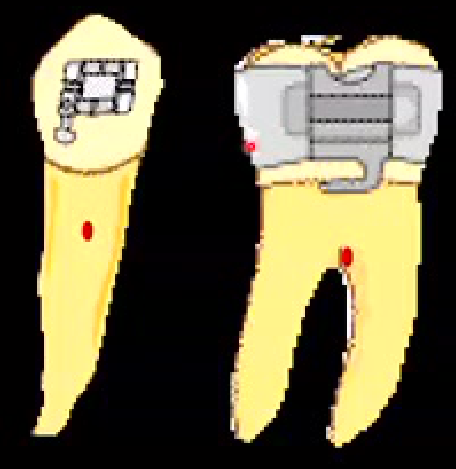
To complete the description of a force, need to define it in relation to the centre of resistance of the tooth.
-
Burstone – from apex usually 2/3 root and just above furcation on molars.
-
This is a theoretical point; if force could be applied through it, the tooth would move bodily without inclination or tipping.
-
Brackets cannot be bonded at this point (it is underneath the bone), so there is always a distance between the bracket slot and the centre of resistance.
Moment and Rotation32
- Define and explain the biomechanical principles that pertain to orthodontics, specifically the meaning of terms such as “force”, “moment”, “fulcrum”, “center of rotation”, and “anchorage” as applied to biomechanics.
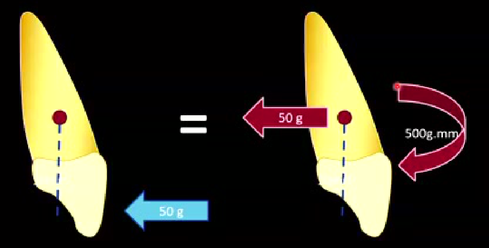
- Moment = Tendency to rotate
- ==Moment = force × distance from the centre of resistance.==
- ==Example: distance = 10 mm, force = 50 g → moment = 500 g·mm.==
- Moment is a vectorial system: it includes the amount of force and its direction.
- If equal forces are applied on both sides with no distance, nothing rotates; the distance creates the rotational tendency.
Couples and Pure Rotation333435
- Couple = Two equal and opposite, non colinear, parallel forces
- Pure rotation around center of rotation (CR)
Application of Couples and Moments3637
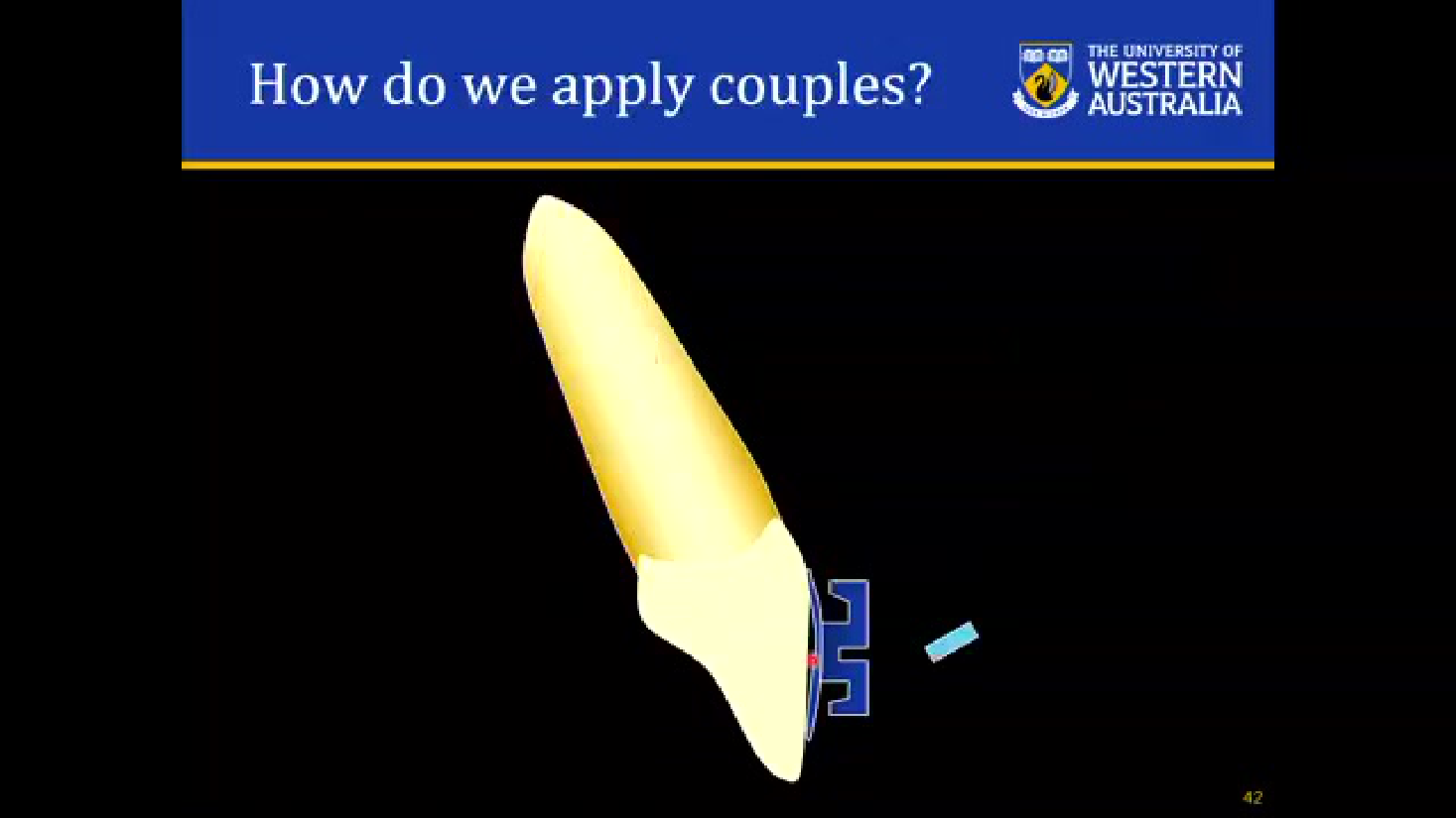
How do we apply couples?
MOMENT = F x d g.mm
- There is always a distance from the bracket to the centre of resistance, so a moment is always generated.
- If force were applied at the centre of resistance, the tooth would move bodily (compression on one side, traction on the other).
- When force is applied below this point (as with a bracket), tipping results, changing the areas of PDL compression.
Types of Tooth Movement
Uncontrolled Tipping
Uncontrolled Tipping3839
- Occurs when the force has a distance from the centre of resistance; tipping is expected.
- The term “uncontrolled” indicates that inclination of the tooth is the expected outcome (though it can be clinically monitored).
Controlled Tipping40414243
- Achieved by using a rectangular wire in a rectangular slot, which produces a second (opposite) moment — a couple of forces.
- The torsion in the wire (or torque built into the bracket) opposes the uncontrolled tipping moment.
- Result: bodily movement with compression on only one side and traction on the other — faster and under control.
- The centre of rotation moves to the apex of the root (a point that does not move during the movement).
=
Controlled Tipping
The text on the page is best understood as labels for a diagram illustrating “Controlled Tipping”. It involves arrows and symbols indicating forces and movement on a tooth, which is typical of a figure.
Translation44
- Bodily movement is achieved through the interaction of moments and couples as described above (translation without tipping).
Wire Mechanics and Physical Properties
- Demonstrate the relationship between wire size, strength, stiffness and the force produced for a given deflection.
Effect of changing wire size45
- Rectangular wire sizes are described by two dimensions (e.g., 16×22, 19×25, 21×25).
- Increasing wire thickness increases engagement in the slot and increases the amount of torque/rotation control.
- Round wire cannot control rotation.
Wire Diameter Effects
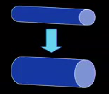
- If you double the diameter of the wire:
- 8 times as STRONG
- 16 times as STIFF
- Will bend ½ as Far
- Halving the diameter reduces stiffness by 8 times and increases springiness by 16 times.
- This is why 0.6 mm stainless steel is used for springs — for high resilience and long-lasting force delivery.
Wire Length Effects46
- Demonstrate the relationship between wire size, strength, stiffness and the force produced for a given deflection.
Effect of changing wire length
- If you make a finger spring twice as long:
- 1/2 as STRONG
- 8 times as springy
- Will bend 4 times as Far
- Loops incorporate more wire into the system, reducing stiffness and increasing springiness.
- Best spring design: incorporate more wire (loops) and reduce the wire thickness.
- Demonstrate the relationship between wire size, strength, stiffness and the force produced for a given deflection.
Effect of changing wire size
- If you double the diameter of the wire:
- 8 times as STRONG
- 16 times as STIFF
- Will bend ½ as Far
Orthodontic Anchorage and Controlled Tooth Movement
Be sure that you are able to:
Clinical Reasoning and Force Systems4748
- Periodontal compromised cases (bone loss): the center of resistance moves apically (staying 2/3 of the remaining root length from the apex).
- This increases the distance from the bracket to the center of resistance.
- With the same force, a larger moment is produced because the distance is increased.
- Therefore, lighter forces must be used for periodontal compromised patients compared to patients with normal periodontium.
- Describe the reaction of a tooth to a single force placed against the crown.
- Describe the reaction of a tooth to a two-force system placed against the crown as a function of the moment-to-force ratio.
- Indicate the changes in orthodontic forces and moments needed for successful movement of a tooth that has lost alveolar bone support (as from previous periodontal disease).
- Describe the adaptations in the contemporary edgewise appliance to reduce in-out (first order) bends in arch wires.
- Describe the adaptations in the contemporary edgewise appliance to reduce angulation (second order) bends in arch wires.
- Describe the adaptations in the contemporary edgewise appliance to reduce torque (third order) bends in rectangular arch wires.
OSCAR Clinical Reasoning exercise
Straightwire Appliance Design49
- Straight wire means the arch wire can be used without bends because the individualization is built into the brackets (e.g., torque built into the slot).
- In a parabolic arch wire, the distance from the wire to the bracket increases toward the posterior; without straightwire brackets, first-order bends (insets of laterals, offsets of canines and 6s) are needed.
- These adaptations are now built into the bracket base/tube position.
Design of the Straightwire Appliance
- Describe the adaptations in the contemporary edgewise appliance to reduce in-out (first order) bends in arch wires.
- Describe the adaptations in the contemporary edgewise appliance to reduce angulation (second order) bends in arch wires.
- Describe the adaptations in the contemporary edgewise appliance to reduce torque (third order) bends in rectangular arch wires.
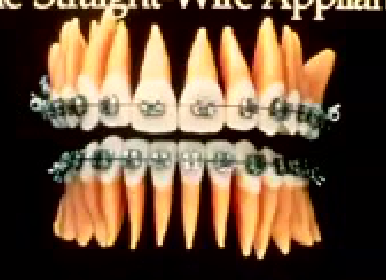
First Order Bends and In-Out Adaptations5051
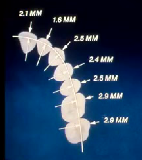
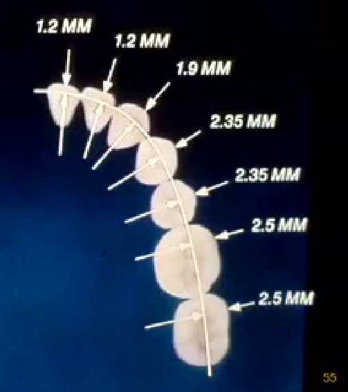
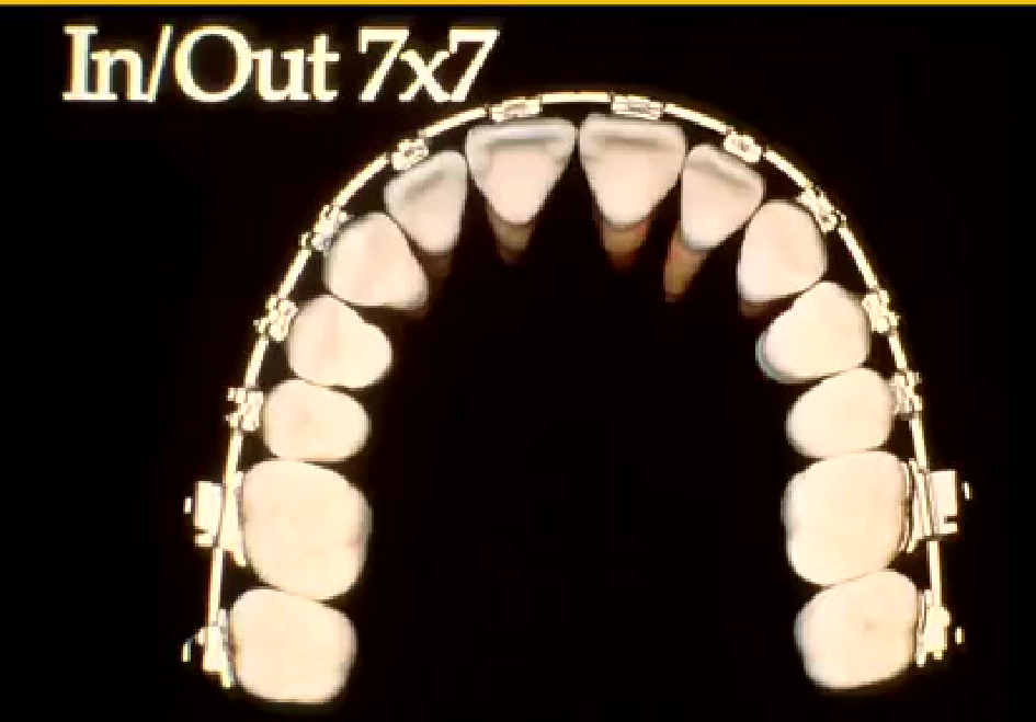
- Compensate for differences in lingual-buccal thickness across teeth.
- Built into the bracket base or tube, so no first-order bends are needed in the wire.
- Describe the adaptations in the contemporary edgewise appliance to reduce in-out (first order) bends in arch wires.
Precise In/Out Measurements
- Describe the adaptations in the contemporary edgewise appliance to reduce in-out (first order) bends in arch wires.
 |  |
 |
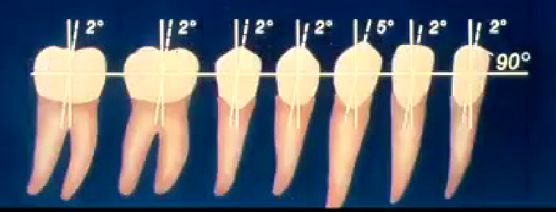
Second Order Bends and Angulation Adaptations52
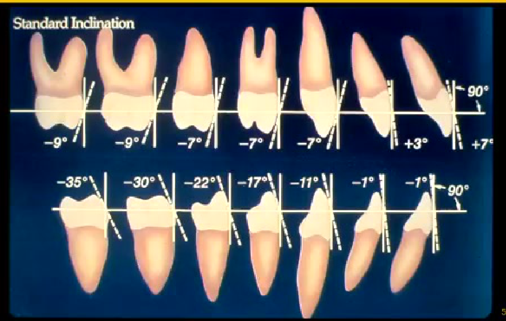
- Compensate for mesiodistal inclination (angulation) of teeth — built into the bracket slot.
- Third order (torque): rotation control built into the slot angulation, replacing torsion that previously had to be placed in the rectangular wire.
- Despite prefabricated brackets, individualized bends are still needed during finishing of a case.
- Describe the adaptations in the contemporary edgewise appliance to reduce angulation (second order) bends in arch wires.
Standard Angulations
Practical Instructions and Supplemental Materials5354
Instructions: E255
Describe the Adams (cannot describe all limitations and strengths are to be recorded in separate column).
Clinical Cases
Case: Transverse Discrepancy and Crossbite Classification
Question
Scenario: Evaluating transverse relationships and differentiating between dental and skeletal crossbites using study models and illustrations. What’s shown: Illustrations comparing a normal palatal width with normal molar inclination, a normal palatal width with excessively lingually tilted upper molars, and a narrow, athrasic upper arch with buccally tilted upper molars. Consider: How to differentiate between a dental crossbite and a skeletal crossbite based on palatal width and the compensatory tilting of the upper molars.
Answer
Observations:
- Normal palatal width with lingually tilted upper molars indicates a dental crossbite.
- A narrow, athrasic upper arch with buccally tilted upper molars indicates a skeletal crossbite.
- In severe skeletal crossbites, the upper arch may be completely lingual to the lower arch without the ability to compensate via tilting. Reasoning: The lecturer explains that if the palatal width (AB distance) is normal but the molars are tilted, the issue is dental. If the palate is narrow (athrasic), the molars may try to compensate by tilting buccally, but the underlying issue is skeletal. Takeaway: Palatal width is the key diagnostic feature to differentiate between dental and skeletal crossbites, as dental crossbites occur with normal palatal width while skeletal crossbites involve a narrow upper arch.
Case: Histological Response to Heavy Orthodontic Forces
Question
Scenario: Examining the biological response of the periodontal ligament (PDL) and alveolar bone to orthodontic forces. What’s shown: An illustration and a histological display using India ink showing the PDL being completely compressed and blood vessels shut off. Consider: What happens to the PDL and the subsequent bone turnover when heavy forces completely block the blood supply.
Answer
Observations:
- The PDL becomes completely squished, leading to sterile necrosis (hyalinization) due to the shut-off of blood vessels.
- Differentiated cells for bone turnover can no longer come from the PDL and must come from the bone itself.
- This results in undermining resorption, which significantly delays orthodontic tooth movement. Reasoning: The lecturer walks through the histological image, explaining that heavy forces cause ischemia and sterile necrosis in the PDL. Because the PDL is necrotic, bone resorption must occur via undermining from the adjacent bone marrow spaces, taking much more time. Takeaway: Heavy orthodontic forces can cause PDL necrosis and hyalinization, leading to undermining resorption and delayed tooth movement; therefore, light forces should be used to maintain PDL vitality.
Case: Anchorage Worked Example for Space Closure
Question
Scenario: Planning orthodontic mechanics for space closure following extractions. What’s shown: A clinical scenario where premolars are extracted to retract the canines and incisors, utilizing the 5th, 6th, and 7th teeth as the anchorage unit. Consider: How to quantify anchorage and manage the anchorage unit to achieve the desired retraction of the anterior teeth.
Answer
Observations:
- The anchorage unit consists of the 5, 6, and 7 teeth, combining their root surface areas to increase resistance to movement.
- The desired movement is the retraction of the canines and incisors (the movement unit).
- The goal is to minimize the movement of the anchorage unit while maximizing the movement of the anterior teeth. Reasoning: The lecturer explains that anchorage is quantified by the root surface area within the bone. By combining multiple posterior teeth, the anchorage unit’s resistance is significantly increased, ensuring that the extraction space is closed primarily by the retraction of the anterior segment. Takeaway: Anchorage is determined by the total root surface area of the teeth used to resist movement; combining multiple teeth reinforces the anchorage unit to prevent unwanted posterior tooth movement during anterior retraction.
Case: Identification of Orthodontic Appliances
Question
Scenario: Identifying various orthodontic appliances from visual examples. What’s shown: Images of a functional appliance, an older crossbite appliance with an omega loop and spring, a Hawley-type removable appliance with Adams clasps and a spring, and a clear aligner. Consider: Identifying the specific appliances shown and their primary functions or mechanisms of action.
Answer
Observations:
- The first appliance is a functional appliance.
- The second is an older crossbite appliance featuring an omega loop for expansion and a spring for anterior correction.
- The third is a Hawley-type removable appliance with Adams clasps for retention and a spring to correct an anterior crossbite.
- The fourth is a clear aligner. Reasoning: The lecturer points out the distinct features of each appliance, such as the omega loop and spring on the older crossbite appliance, and the specific clasps and springs on the Hawley appliance, linking them to their historical or current clinical uses. Takeaway: Recognizing the structural components of removable and functional appliances, such as omega loops, Adams clasps, and springs, helps in understanding their specific clinical applications for crossbite correction and expansion.
Case: Removable Appliance Design for Anterior Crossbite
Question
Scenario: Designing a removable appliance to correct an anterior crossbite of a central incisor. What’s shown: An image of a removable appliance featuring an Adams clasp, a ball clasp, a Hawley clasp, and a finger spring underneath the acrylic plate. Consider: How the components of the appliance provide retention and how the spring is activated to apply force to the incisor.
Answer
Observations:
- Retention is achieved using an Adams clasp, a ball clasp, and a Hawley clasp.
- A finger spring made of 0.6 or 0.7 mm stainless steel wire is located underneath the acrylic plate.
- The spring is activated by pulling the wire down towards the cervical part of the incisor. Reasoning: The lecturer describes the design, noting that stainless steel is used instead of NiTi because it can be bent to form the spring loops. The clasps balance the retention against the force of the spring to keep the appliance in place during function. Takeaway: In removable appliance design, adequate retention via clasps must be balanced against the active force of the spring, and stainless steel wire is preferred for springs because it can be bent to incorporate loops for increased resilience.
Case: Biomechanics of Tooth Movement and Tipping
Question
Scenario: Analyzing the biomechanics of applying an orthodontic force to a bracket. What’s shown: A diagram illustrating the center of resistance, the point of force application at the bracket, and the distance between them, demonstrating uncontrolled tipping versus controlled tipping with a rectangular wire. Consider: How the distance from the center of resistance creates a moment, and how to achieve controlled tipping or bodily movement using rectangular wires.
Answer
Observations:
- Applying a force at the bracket, which is distant from the center of resistance, creates a moment that results in uncontrolled tipping.
- Using a rectangular wire in a rectangular bracket slot produces an opposing moment (torsion) that counteracts the tipping.
- This interaction allows for controlled tipping or bodily movement without needing to apply force directly at the center of resistance. Reasoning: The lecturer explains that the moment is the product of the force and the distance to the center of resistance. By engaging a rectangular wire, a counter-moment is generated, neutralizing the tendency for uncontrolled tipping and allowing the tooth to move in a controlled manner. Takeaway: Because orthodontic brackets are placed at a distance from the center of resistance, applying a single force causes uncontrolled tipping; engaging a rectangular wire creates a counter-moment that allows for controlled tipping or bodily movement.
Case: Biomechanics in Periodontally Compromised Patients
Question
Scenario: Planning orthodontic mechanics for a patient with periodontal bone loss. What’s shown: A clinical scenario describing a periodontally compromised patient where alveolar bone loss has occurred. Consider: How periodontal bone loss affects the center of resistance and the resulting orthodontic forces required for tooth movement.
Answer
Observations:
- Bone loss moves the center of resistance apically, closer to the apex of the root.
- This increases the distance between the bracket (where force is applied) and the center of resistance.
- The increased distance results in a larger moment (couple) for the same amount of force. Reasoning: The lecturer explains that because the center of resistance shifts apically due to bone loss, the moment arm increases. To prevent excessive tipping and manage the larger moment, significantly lighter forces must be used compared to a patient with normal periodontal support. Takeaway: In periodontally compromised patients, apical bone loss shifts the center of resistance apically, increasing the moment arm; therefore, much lighter orthodontic forces are required to achieve controlled tooth movement.
Case: Straight Wire Appliance Bracket Compensations
Question
Scenario: Understanding the built-in compensations in a straight wire bracket system. What’s shown: An illustration showing the base of a bracket or tube with specific angulations and compensations for first, second, and third-order bends. Consider: How the bracket base incorporates first, second, and third-order bends to eliminate the need for wire bending during initial alignment.
Answer
Observations:
- First-order bends (buccal-lingual offsets) are built into the base of the bracket or tube.
- Second-order bends (mesio-distal inclinations/angulations) are incorporated into the bracket design.
- Third-order bends (torque/rotations) are built into the angle of the bracket slot itself. Reasoning: The lecturer points out that the “straight wire” concept relies on these pre-built compensations in the bracket base and slot angulation. This eliminates the need for the clinician to place complex first, second, and third-order bends in the archwire during the initial stages of treatment. Takeaway: The straight wire appliance system incorporates first, second, and third-order bends directly into the bracket base and slot angulation, simplifying archwire bending and streamlining the alignment process.
Footnotes
-
Original PDF page 1: L2 3A unit review slides, p.1 ↩
-
Original PDF page 2: L2 3A unit review slides, p.2 ↩
-
Original PDF page 3: L2 3A unit review slides, p.3 ↩
-
Original PDF page 4: L2 3A unit review slides, p.4 ↩
-
Original PDF page 5: L2 3A unit review slides, p.5 ↩
-
Original PDF page 7: L2 3A unit review slides, p.7 ↩
-
Original PDF page 10: L2 3A unit review slides, p.10 ↩
-
Original PDF page 11: L2 3A unit review slides, p.11 ↩
-
Original PDF page 12: L2 3A unit review slides, p.12 ↩
-
Original PDF page 13: L2 3A unit review slides, p.13 ↩
-
Original PDF page 14: L2 3A unit review slides, p.14 ↩
-
Original PDF page 15: L2 3A unit review slides, p.15 ↩
-
Original PDF page 16: L2 3A unit review slides, p.16 ↩
-
Original PDF page 17: L2 3A unit review slides, p.17 ↩
-
Original PDF page 18: L2 3A unit review slides, p.18 ↩
-
Original PDF page 19: L2 3A unit review slides, p.19 ↩
-
Original PDF page 21: L2 3A unit review slides, p.21 ↩
-
Original PDF page 23: L2 3A unit review slides, p.23 ↩
-
Original PDF page 24: L2 3A unit review slides, p.24 ↩
-
Original PDF page 25: L2 3A unit review slides, p.25 ↩
-
Original PDF page 26: L2 3A unit review slides, p.26 ↩
-
Original PDF page 27: L2 3A unit review slides, p.27 ↩
-
Original PDF page 28: L2 3A unit review slides, p.28 ↩
-
Original PDF page 29: L2 3A unit review slides, p.29 ↩
-
Original PDF page 30: L2 3A unit review slides, p.30 ↩
-
Original PDF page 31: L2 3A unit review slides, p.31 ↩
-
Original PDF page 32: L2 3A unit review slides, p.32 ↩
-
Original PDF page 33: L2 3A unit review slides, p.33 ↩
-
Original PDF page 34: L2 3A unit review slides, p.34 ↩
-
Original PDF page 35: L2 3A unit review slides, p.35 ↩
-
Original PDF page 36: L2 3A unit review slides, p.36 ↩
-
Original PDF page 37: L2 3A unit review slides, p.37 ↩
-
Original PDF page 38: L2 3A unit review slides, p.38 ↩
-
Original PDF page 39: L2 3A unit review slides, p.39 ↩
-
Original PDF page 40: L2 3A unit review slides, p.40 ↩
-
Original PDF page 42: L2 3A unit review slides, p.42 ↩
-
Original PDF page 43: L2 3A unit review slides, p.43 ↩
-
Original PDF page 44: L2 3A unit review slides, p.44 ↩
-
Original PDF page 45: L2 3A unit review slides, p.45 ↩
-
Original PDF page 46: L2 3A unit review slides, p.46 ↩
-
Original PDF page 47: L2 3A unit review slides, p.47 ↩
-
Original PDF page 48: L2 3A unit review slides, p.48 ↩
-
Original PDF page 49: L2 3A unit review slides, p.49 ↩
-
Original PDF page 50: L2 3A unit review slides, p.50 ↩
-
Original PDF page 51: L2 3A unit review slides, p.51 ↩
-
Original PDF page 54: L2 3A unit review slides, p.54 ↩
-
Original PDF page 55: L2 3A unit review slides, p.55 ↩
-
Original PDF page 56: L2 3A unit review slides, p.56 ↩
-
Original PDF page 57: L2 3A unit review slides, p.57 ↩
-
Original PDF page 58: L2 3A unit review slides, p.58 ↩
-
Original PDF page 59: L2 3A unit review slides, p.59 ↩
-
Original PDF page 60: L2 3A unit review slides, p.60 ↩
-
Original PDF page 62: L2 3A unit review slides, p.62 ↩
-
Original PDF page 63: L2 3A unit review slides, p.63 ↩
-
Original PDF page 61: L2 3A unit review slides, p.61 ↩