Dental Surveying and Partial Denture Design
This document outlines the components of the dental surveyor, the instrumentation used in the surveying process, and the fundamental principles of cast partial denture design, including tripoding and clasp selection.
I. The Dental Surveyor: Components and Instrumentation
The dental surveyor is a diagnostic instrument
 used to determine the relative parallelism of oral structures and identify the ideal path of insertion for a prosthesis.
Surveyor Parts
- Base: The stable foundation of the unit.
- Vertical & Horizontal Arms: Support the surveying assembly.
- Adjustable Survey Spindle: Moves vertically
 and contains a collet to secure various instruments.
- Adjustable Survey Table: Features locking screws
 at the side and back to secure the diagnostic model. It is tilted to manipulate the path of insertion and dislodgement.
Surveying Instruments
| Instrument | Description | Purpose |
|---|---|---|
| Analyzing Rod | A straight, slightly tapered metal shank. | Used to check parallelism and identify undercuts without marking the model. |
| Undercut Gauges | Available in three sizes: 0.25mm (one line), 0.50mm (two lines), and 0.75mm (thickest thimble). | Measures the specific depth of an undercut for clasp placement. The 0.25mm gauge is most common. |
| Graphite/Lead Holder | Two metal half-cylinders that protect the graphite from fracturing. | Used to mark the height of contour (survey line) on the teeth. |
| Wax Scalpel | A metal blade attachment. | Used in treatment planning to reduce tooth structure on a model (e.g., creating guide planes). |


II. The Surveying Process
1. Preliminary Assessment
Before surveying, identify the abutment teeth—typically those adjacent to edentulous (missing teeth) areas. In the current exercise, these are teeth 34 and 44.

2. Establishing the Path of Insertion
- Place the model on the survey table with the base against the support legs.
- Use the analyzing rod to find a “set zero” position
 where undercuts on guide surfaces are minimized or eliminated.
- Balance the height of contour between the left and right abutment teeth to ensure an even path of insertion.
3. Tripoding the Model
Tripoding ensures the model can be returned to the exact same tilt if removed from the surveyor.
- Method A (Axis Marking): Mark the X and Y axes
on the base of the model relative to the survey spindle.
- Method B (Tissue Marking): Use the spindle to mark three widely spaced points
on the soft tissue areas of the model at a fixed vertical height. Circle these points (bullseyes) for visibility.
4. Delineating the Height of Contour
Replace the analyzing rod with the **graphite marker
**. Gently rotate the model against the lead to mark the height of contour (the widest part of the tooth at that specific tilt). Areas below this line are undercuts; areas above are non-retentive.
- find the where the HOC is 0.25mm and then put a point, this is where the tip of the clasp goes
III. Partial Denture Design Components
Major and Minor Connectors
- Lingual Bar: A common mandibular major connector
. It should be placed 3–5 mm below the gingival margins.
- Minor Connectors: Join the components (clasps, rests, etc.) to the major connector.
- Acrylic Retention (Mesh): A grid-like structure
 designed to hold the denture teeth and acrylic base. It should be kept slightly above the tissue to allow room for the acrylic.
The Four Parts of a Clasp
Every clasp assembly must contain these four functional elements:
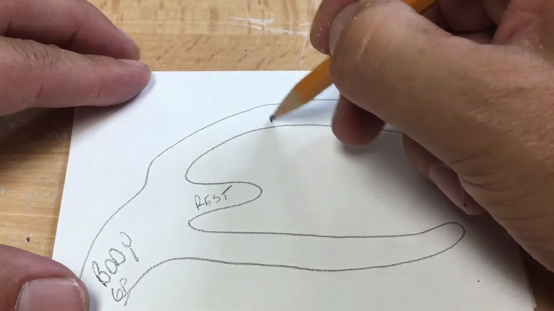
- Rest: Prevents vertical movement toward the tissue (occlusal support).
- Body/Guide Plane: Connects the clasp to the minor connector and provides stability.
- Retentive Arm: A flexible arm where the terminal third sits below the height of contour (engaging the undercut).
- Reciprocal (Bracing) Arm: A rigid arm placed above the height of contour to counteract the forces exerted by the retentive arm.
IV. Classification of Clasps
Suprabulge Clasps
These clasps approach the undercut from above the height of contour (occlusal direction).
- Akers Clasp (E-Clasp): The most common clasp; shaped like the letter ‘E
 ‘.
‘.
- G-Clasp: Similar to the Akers but with the rest positioned
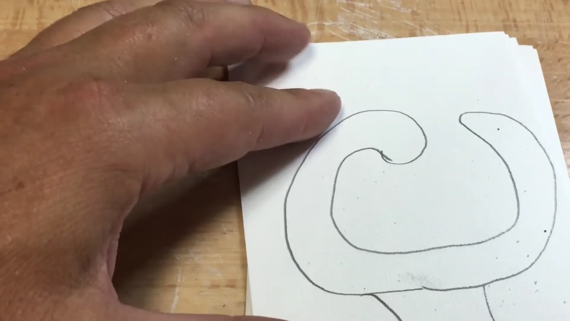 on the opposite side of the guide plane.
- Embrasure Clasp (Double Akers/Bonwill): Essentially two Akers clasps
 joined together; used when there is no edentulous space on one side of the arch.
- Hairpin Clasp: A retentive arm that loops back on itself
 ; used when the undercut is adjacent to the minor connector.
- Back Action Clasp: A continuous arm where the minor connector
 originates from the rest.
- Ring Clasp: Encircles nearly the entire tooth
 ; typically used on isolated molars.
Infrabulge Clasps (Roach Clasps)
These clasps approach the undercut from below the height of contour (gingival direction).
- I-Bar: A straight bar approaching the center of the tooth
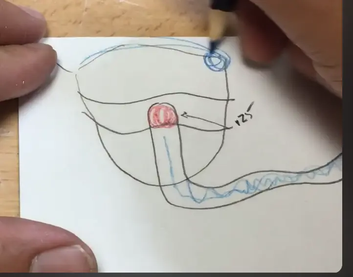
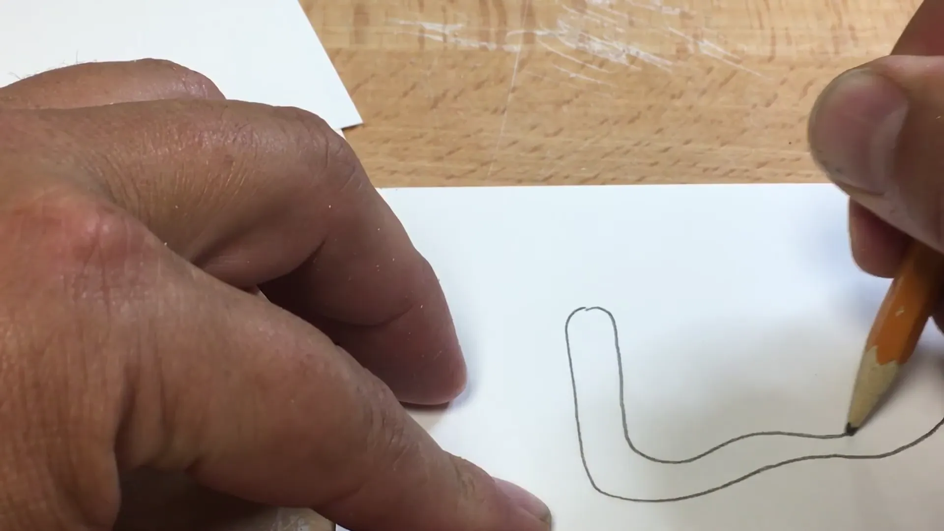 ; highly aesthetic and functional.
 - Y-Bar: Approaches the undercut in a ‘Y’ shape
 .
.
- Half-Y (Modified Roach): Used when an undercut is only present
 on one half of the tooth surface.
- J-Bar: Approaches from the gingival but curves across the facial surface.
V. Summary of Clinical Workflow
- Identify Kennedy Classification: Determine the type of edentulous space.
- Select Major Connector: Based on the classification and anatomical constraints.
- Survey the Model: Establish the path of insertion and tripod the model.
- Design Clasps: Select the appropriate suprabulge or infrabulge clasp based on the location of undercuts (0.25mm) and biomechanical needs.
- Final Outline: Draw the design in red (retentive) and blue (passive/bracing) on the diagnostic model.