Removable Partial Dentures Overview
A Removable Partial Denture (RPD) is a dental prosthesis that replaces one or more missing teeth and associated structures in a partially edentulous arch and can be removed by the patient. This note is the canonical RPD landing page for the UWA DMD3S1 curriculum — a synthesis of the L1–L10 lecture series, McCracken’s textbook annotations, Mental Dental videos, and the OCHWA clinical protocol. Use it as a study scaffold and a navigation hub: each subsection links out to the underlying lecture or chapter where the detail lives.
Summary
Definition, Indications & Decision-Making
- Three prosthetic options for partial edentulism: implant, fixed partial denture (FPD), or RPD. The decision is driven by abutment quality, span length, ridge anatomy, hygiene, and patient factors (age, dexterity, finances, medical contraindications to surgery).
- Ante’s Law: total root-surface area of the abutments for an FPD must be ≥ root-surface area of teeth replaced. Long spans, distal-extension cases, and weak abutments fail this test → RPD or implant.
- Indications for RPD (L1): long-span edentulous areas; absent distal abutment (free-end saddle); reduced periodontal support; need for cross-arch stabilization; excessive bone loss requiring labial flange support; limited manual dexterity; financial/medical contraindication to implants; interim use during healing or staged treatment.
- Disadvantages of clasp-retained RPDs (L4): increased caries risk and plaque accumulation around clasps; PDL strain on abutments if poorly designed; metal display (aesthetics).
- Chrome (Co-Cr) vs acrylic (L1, L4):
- Chrome — thinner, tooth-supported, longer-lasting, requires healthy abutments and meticulous design; higher lab cost.
- Acrylic — tissue-supported, no rest seats needed, bulkier, cheaper, easier to add teeth; preferred when abutments are periodontally compromised or vertical space is severely limited.
Combination Syndrome (Kelly's syndrome) (L1)
When a maxillary complete denture opposes a mandibular Kennedy I RPD (or natural anterior dentition opposing edentulous maxilla):
- Anterior maxillary ridge resorption
- Tuberosity hypertrophy
- Mandibular anterior tooth extrusion
- Ridge atrophy under the RPD bases — leading to decreased prosthetic space
Mitigated by maintaining bilateral posterior support and balanced occlusion.
Unilateral designs are prohibited (L2)
A framework that extends to only one side of the arch can lift during function and be aspirated. All RPDs must extend bilaterally across the arch regardless of how few teeth are missing.
Classification & Support
Kennedy Classification — most posterior edentulous area determines the class
| Class | Pattern | Diagram |
|---|---|---|
| I | Bilateral distal edentulous areas (tooth-and-tissue-supported) | 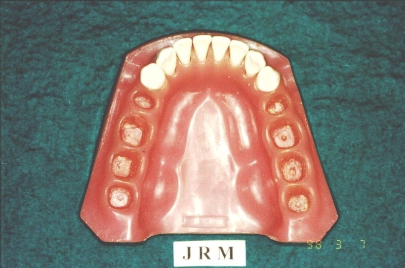 |
| II | Unilateral distal edentulous area | 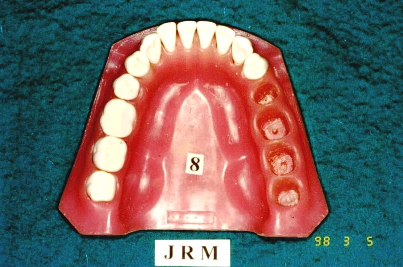 |
| III | Unilateral edentulous area bounded by teeth (tooth-supported — best prognosis) | 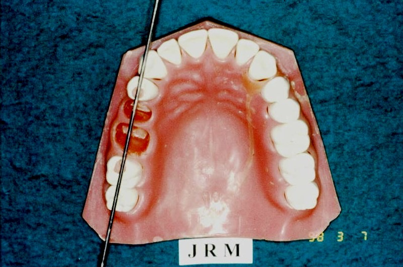 |
| IV | Single anterior edentulous area crossing the midline (no modifications allowed) | 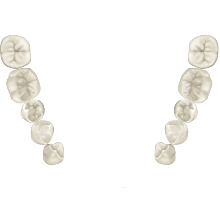 |
- Modifications = additional edentulous spaces beyond the one defining the class. Count the number of spaces, not teeth. Class IV has no modifications by definition.
- Example: free-end posterior right + bounded anterior + bounded left posterior = Class II Modification 2.
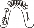
Applegate’s 8 Rules (L2)
| # | Rule |
|---|---|
| 1 | Classification follows extractions — extract first, then classify |
| 2 | Missing 3rd molar not to be replaced → not counted |
| 3 | 3rd molar present and used as abutment → counted |
| 4 | Missing 2nd molar not to be replaced → not counted |
| 5 | Most posterior edentulous area always determines the class |
| 6 | Other edentulous areas are designated as modifications, by number only |
| 7 | The extent of a modification doesn’t matter — only that it exists |
| 8 | No modifications in Class IV (any posterior space reclassifies the case as I/II/III with the anterior space as a modification) |
Support type — predicts prognosis
| Support type | Load goes to | Typical Kennedy class | Prognosis |
|---|---|---|---|
| Tooth-supported | Periodontium of abutments | All Class III | Best — patients rarely complain of mucosal pain |
| Tooth-and-tissue-supported | Mixed (distal extension) | Class I, II, IV (long spans) | Variable — depends on free-end saddle management |
| Tissue-supported | Mucosa only (acrylic denture) | Heavily resorbed Class I when chrome is contraindicated | Poorest — risk of accelerated bone resorption |
- Why Class III has the best prognosis: bounded saddle + tooth support means no rotation and no mucosal compression.
- Biomechanical view: intercalated (bounded), levered (free-end), combined (both). Levered cases need indirect retention; intercalated cases generally don’t.
Components & Function
The seven RPD components (L2)
| # | Component | Function |
|---|---|---|
| 1 | Rest | Vertical support; transmits occlusal load along the long axis of the abutment |
| 2 | Retentive arm | Engages undercut via elastic deformation; resists vertical dislodgement |
| 3 | Reciprocal arm | Rigid, above HOC; counters the horizontal force from the retentive arm |
| 4 | Proximal plate | Contacts guiding plane; defines path of insertion; aids stabilization and reciprocation |
| 5 | Major connector | Cross-arch rigid backbone; distributes force; assists indirect retention |
| 6 | Minor connectors | Right-angle joins of clasp/saddle to the major connector |
| 7 | Saddle (denture base) | Carries artificial teeth; transmits force to ridge; anterior flange supports the lip |
| Components diagram | Direct vs indirect retainer |
|---|---|
 | 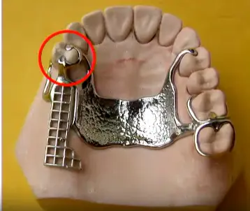 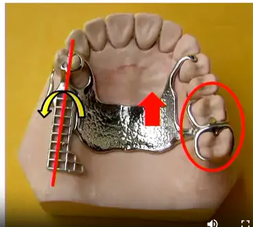 |
Ceramic teeth on RPDs (L2)
Decline ceramic teeth — they don’t bond to acrylic, add weight to upper dentures, click during function, and abrade opposing enamel. Use acrylic or composite teeth instead.
Direct vs indirect retainers — the fulcrum line
- Fulcrum line = the rotation axis through the most posterior direct retainers. Forces beyond it tip the saddle.
- Direct retainer sits adjacent to the edentulous space → prevents vertical dislodgement of the saddle.
- Indirect retainer sits anterior to the fulcrum line, as far from it as possible → prevents rotation when sticky food lifts the free-end saddle.
- In a Class I case, three potential fulcrum lines exist (each posterior abutment, plus both together for anterior loading). Distribute indirect retention across canines/premolars to avoid loading single incisors.
Six requirements of every retentive unit (L4) — mnemonic: S-S-R-R-E-P
| # | Requirement | Provided by |
|---|---|---|
| 1 | Support | Rest |
| 2 | Stabilization (bracing) | Reciprocal arm + proximal plate + initial third of retentive arm |
| 3 | Retention | Terminal third of retentive arm in the undercut |
| 4 | Reciprocity | Reciprocal arm contacts tooth simultaneously with retentive arm |
| 5 | Encirclement | >180° encirclement of the tooth so it cannot escape laterally |
| 6 | Passivity | Zero force on tooth when fully seated (avoids PDL damage) |
Rests and rest seats (L3)
| Property | Occlusal | Cingulum (lingual) | Incisal |
|---|---|---|---|
| Shape | Rounded triangular | Inverted-smile (M/D convex, B/L concave V) | Concave M/D, convex B/L |
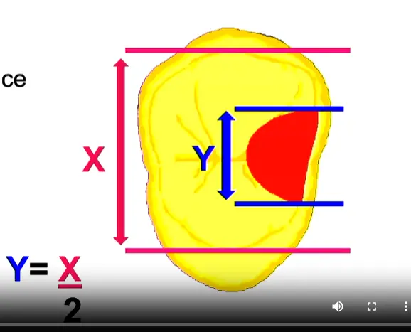
| Width B/L | ½ inter-cusp distance | — | 2.5 mm |
| Depth | 0.5 mm at point, 1.0–1.5 mm at marginal ridge | ≥0.8 mm reduction | 1.5 mm |
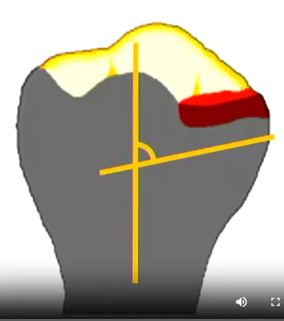
| Floor angle | <90° (apically inclined) | <90° | <90° |
| Best on | Molars, premolars | Canines (bulky cingulum) | Last resort if lingual interferes |
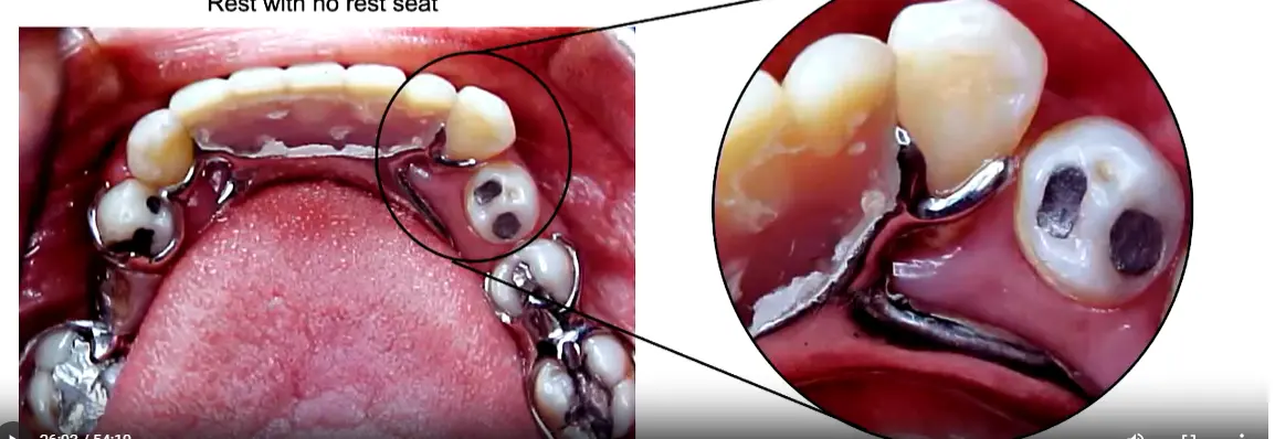
- Why preparation is mandatory: without a seat, the lab makes a tall metal contour over the natural surface → patient bites high → grinding the metal makes the rest dangerously thin. Even with no opposing tooth, prepare a seat to direct force along the long axis.
- Why box-shaped seats fail: sharp angles concentrate load, prevent rotational accommodation, and trap plaque. Always rounded.
- Floor >90° tips the tooth — load slides toward the proximal contact and causes mobility if that contact is lost.
| Occlusal seat morphology | B/L width formula | M/D vs B/L | Summary | Tipping when no seat |
|---|---|---|---|---|
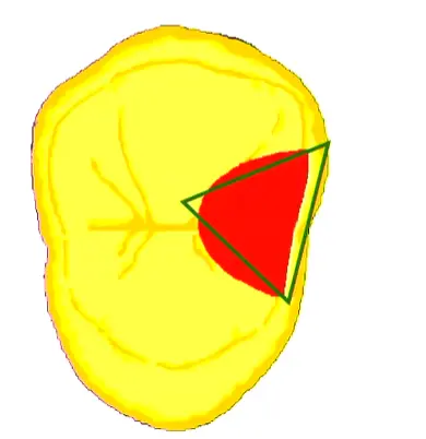 |  |  |  |  |
Rest placement by Kennedy class
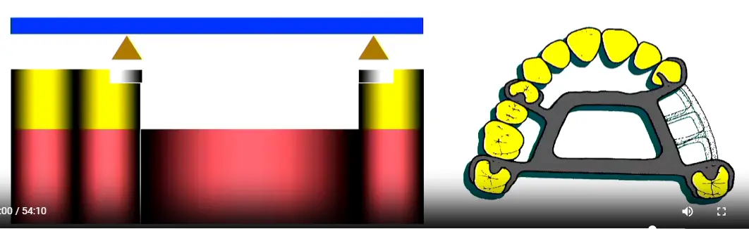
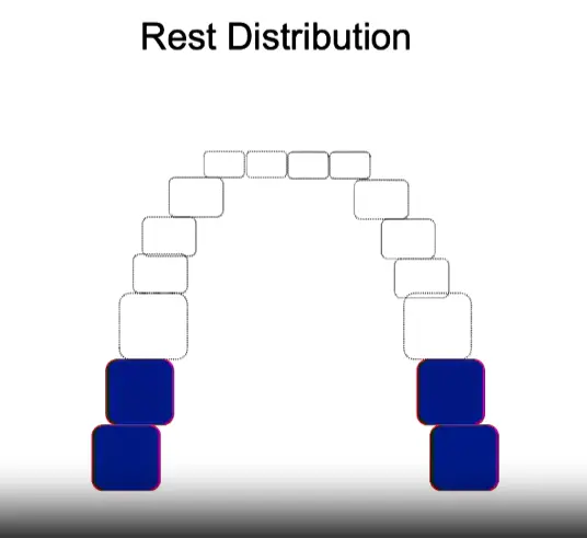
- Class III (tooth-bounded): place rests adjacent to the edentulous space — proximal contact resists tipping.
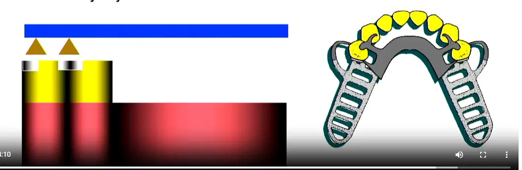
- Class I/II (free-end): place rests mesial to the terminal abutment. A distal rest would tip the tooth distally toward the saddle. Mesial rest = mesial contact = anti-tipping.
- Class IV (anterior): treat as a free-end saddle toward the mesial — place the rest on the distal of the adjacent canine.
| Intercalated placement (Class III) | Free-end placement (Class I/II) | Class IV placement |
|---|---|---|
 |  |  |
Clasp assembly (L4)
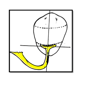
- Retention mechanism: elastic deformation of the terminal third of the retentive arm into a tooth undercut. Exceeding the elastic limit = plastic deformation = permanent loss of retention.
- Five flexibility factors: arm length, taper, cross-section, diameter, material.
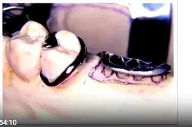
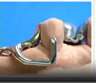
- Suprabulge clasps approach the undercut from the occlusal direction (continuous tooth contact). Infrabulge (bar) clasps approach from the apical direction (short tooth contact, stress-releasing on free-ends).
- Terminal-third never-adjust rule: only the proximal 2/3 of the retentive arm is adjustable. Touching the terminal third destroys retention.
| Suprabulge approach | Infrabulge approach | Retentive arm sections |
|---|---|---|
 |  |  |
Clasp types matched to indication
| Clasp | Indication | Limitations | Diagram |
|---|---|---|---|
| Akers / simple circumferential | Standard intercalated cases; molars, premolars, non-aesthetic canines | Not ideal if abutment tilts toward edentulous space | 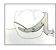 |
| Reverse circumferential | Abutment tilted toward edentulous space | Short clinical crowns; insufficient connector space | 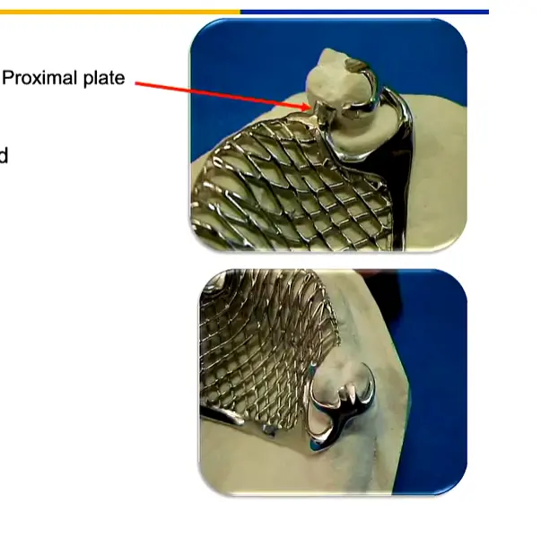 |
| Ring | Mesiolingually tipped lower molar; intercalated areas | Not suitable for free-ends | 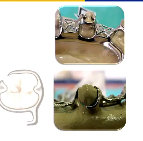 |
| Embrasure | Indirect retention between two adjacent posterior teeth (perpendicular to fulcrum line) | Requires extensive marginal ridge prep | 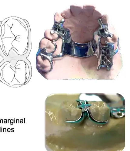 |
| T-bar / modified T / I-bar | Aesthetic zones; free-end saddles | Frenum interference; severe undercuts trap food | 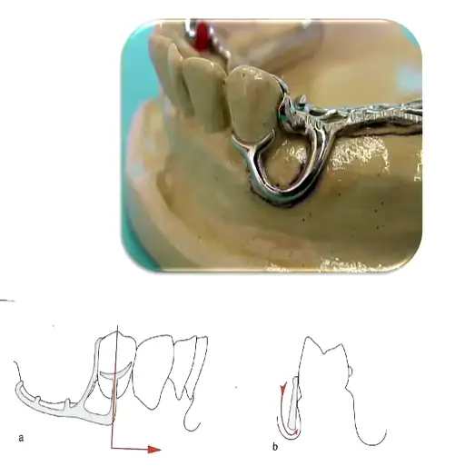 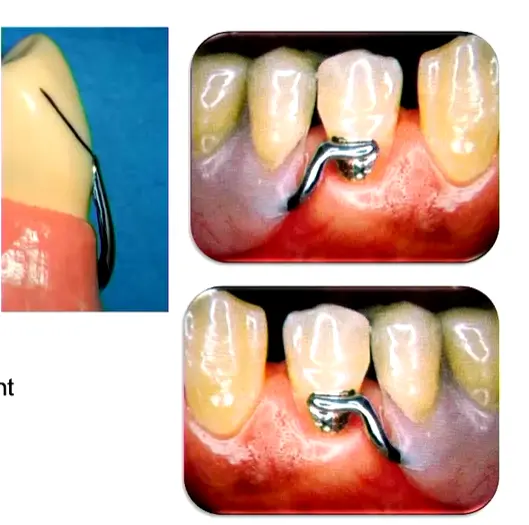 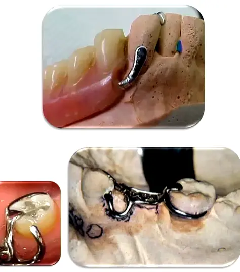 |
| RPI (Rest, Proximal plate, I-bar) | Kennedy I/II free-end on premolar/molar — gold standard | Contraindicated on canines/incisors (emergence profile blocks proximal plate) | 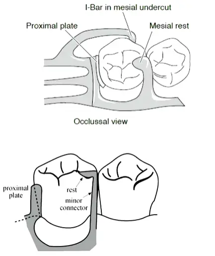 |
- RPI rationale: no separate reciprocal arm — the mesial rest + distal proximal plate together provide reciprocation. The I-bar engages a mesio-buccal undercut and disengages on function (stress-release).
Guiding planes
- Required for all clasps: parallel flat surfaces on the proximal (and sometimes lingual) of abutments, prepared with a parallel diamond bur (not tapered).
- Minimum vertical height: 2–3 mm. 1 mm is insufficient.
- Extent: occlusal 1/3 to 2/3 of the crown, ≥2/3 of the crown height.
- Function: defines a single path of insertion; provides frictional retention; activates the proximal plate; reduces food impaction.
Major Connectors
Merged content
The following Maxillary, Mandibular, and General Principles sections are absorbed verbatim from the prior
Partial Dentures - Indications for Clasps and Connectors Overview (rough).md. Footnote-style citations preserved at the end of this note.
Maxillary
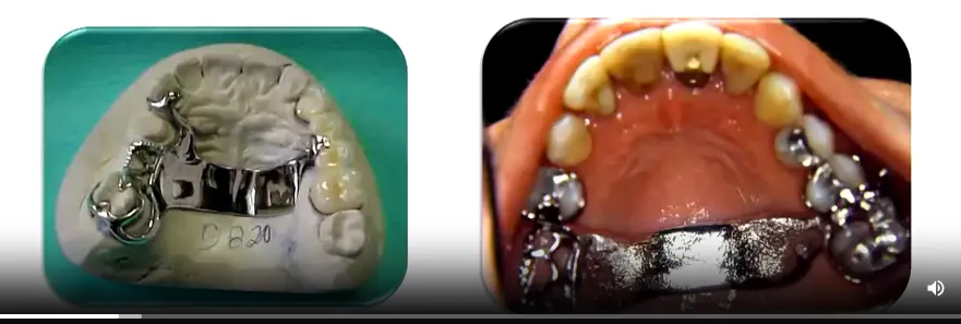
Single Palatal Strap
- Kennedy Class III without anterior modification
- ≥ 8 mm wide for rigidity, kept thin for tongue comfort
- Borders follow the valleys of the rugae rather than crossing over them
- Both anterior and posterior borders should cross the midline at right angles for optimal rigidity
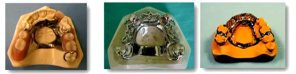
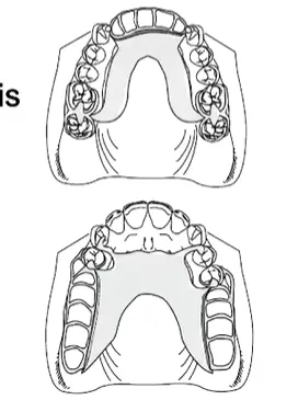
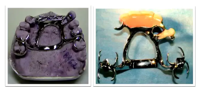
Anterior-Posterior Palatal Strap
- Kennedy Class II, Class III with anterior modification, and Class IV
- Preferred “closed oval” skeletal design for Class I long distal-extension spans — excellent rigidity3
- Each strap ≥ 8 mm wide, flat profile
- Posterior strap placed anterior to the hard/soft palate junction — avoids the vibrating line and the gagging/instability that results from crossing it
- The overall width of the connector should correspond roughly to the amount of posterior occlusion being replaced4
- Minimise coverage of the anterior rugae to preserve sibilants (/s/, /z/) and alveolar sounds (/t/, /d/)
- Contraindicated where an inoperable torus extends onto the soft palate
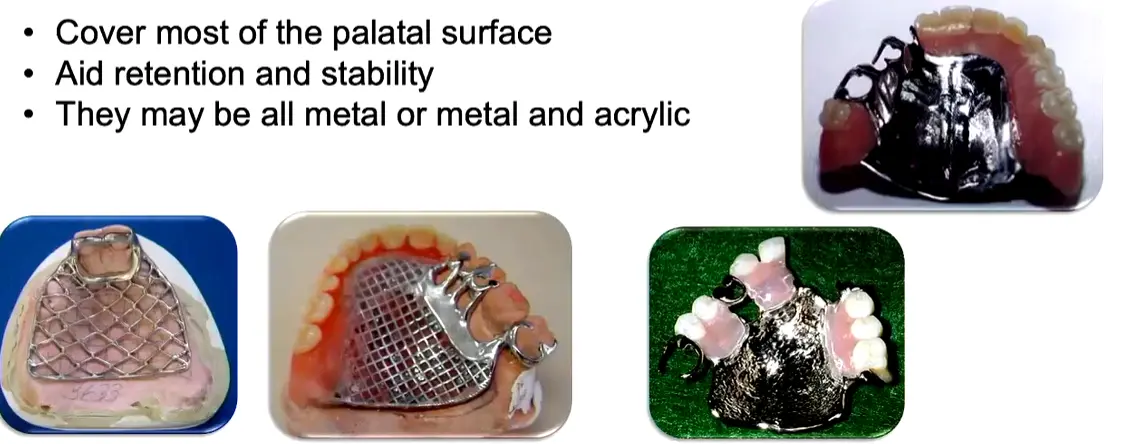
Palatal Plate (Complete Palatal Coverage)
- Few remaining teeth (e.g. only anterior teeth present)
- Remaining teeth with a guarded prognosis
- Long, flat or flabby residual ridges; shallow vaults; small mouths
- Most common choice for Kennedy Class I5
- Long-span Class IV (“pseudo-Class V” — 6–8 anterior teeth missing), where a horseshoe is often insufficient and palate depth or a prominent mid-palatine raphe rules out a closed-oval strap6
- Most rigid maxillary major connector — provides substantial retention/stability via intimate tissue contact
- All-metal vs metal + acrylic: metal conducts temperature, aiding patient adaptation and taste; only mesh/acrylic variants permit future relining
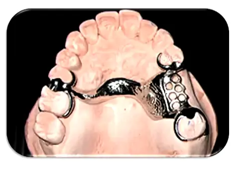
Horseshoe
- Inoperable large palatal torus (patient declines surgical removal)
- Significant gag reflex
- Some Class IV presentations
- Poorest maxillary connector for rigidity — use sparingly
- Requires bulk in the rugae zone where tongue space is most valued
- Often insufficient for long-span Class IV — switch to a closed-oval A-P strap or a full palatal plate depending on palate depth and mid-palatine raphe prominence6
Single Palatal Bar
- Kennedy Class III with a small edentulous span only
- Contraindicated in Class I and Class II (insufficient vertical support, poor rigidity)
- < 8 mm wide, narrow half-oval cross-section
- Do not place anterior to the 2nd premolar — profile is bulky
- Ideal placement is in the median region, behind the rugae
Anterior-Posterior Palatal Bars (Double Bar)
- Absence of many teeth (anterior and posterior)
- Presence of a palatal torus
- Two flat longitudinal elements per side; the anterior portion is typically less bulky
- High rigidity with minimal soft-tissue coverage
- Multiple borders can be uncomfortable for the tongue
Mandibular
In general it seems as though mandibular major connector selection is guided by anatomic considerations more so than Kennedy classes (i.e. we need a reason to not use a lingual bar, otherwise just keep it simple).
Lingual Bar
Indications
- When depth of the lingual vestibule is ≥ 7 mm
- Simplest and most common mandibular major connector
Vestibular space is critical
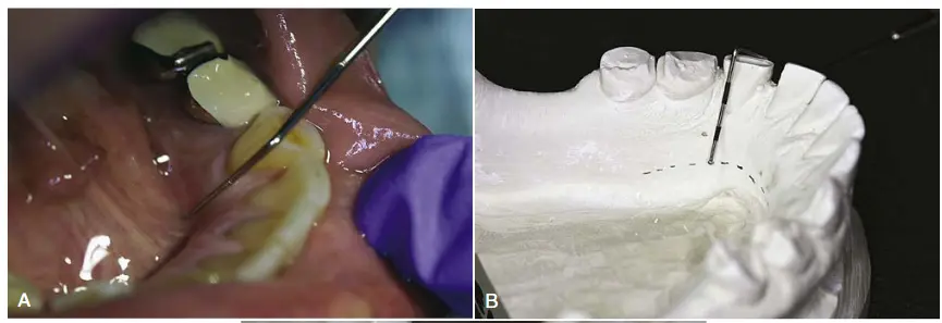
Two methods to determine relative height of the floor of mouth and locate the inferior border:
- Periodontal probe to measure floor of mouth height vs. lingual gingival margins
- 7 mm is Mental Dental’s estimate; McCracken simply requires non-impingement on the floor of mouth tissue
- Lectures recommend 8 mm of space2 = 5 mm bar height + 3 mm clearance from gingival margin
Drawing tips7
- Maintain 0.3–0.5 mm clearance from the lingual tissue
- Place the bar 3–5 mm below the gingival margins
- If a deep soft-tissue undercut is present, the lingual bar may create a food trap or speech impediment — a linguoplate is the better choice in that situation7
Lingual Plate (Linguoplate)
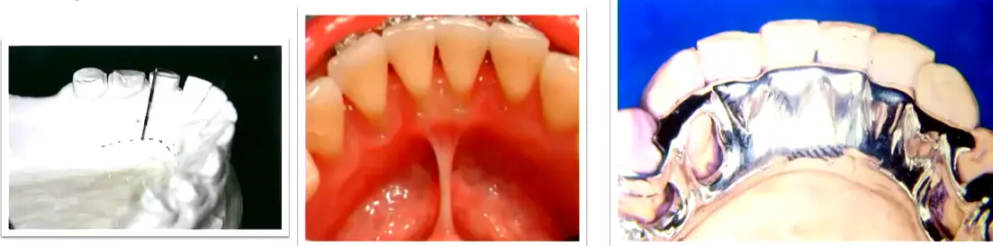
Indications8
- When the lingual frenum is high or the space available for a lingual bar is limited
- Class I cases where residual ridges have undergone excessive vertical resorption
- Stabilizing periodontally weakened teeth
- When future replacement of incisors will be facilitated by addition of retention loops to an existing linguoplate
“Generally, the apron is used to avoid gingival irritation or entrapment of food debris or to cover generously relieved areas that would be irritating to the tongue” (Carr & Brown, 2015, p. 35)
Other Mandibular Major Connectors
Generally rare; used when teeth are very tilted or there are extensive hard/soft tissue undercuts. 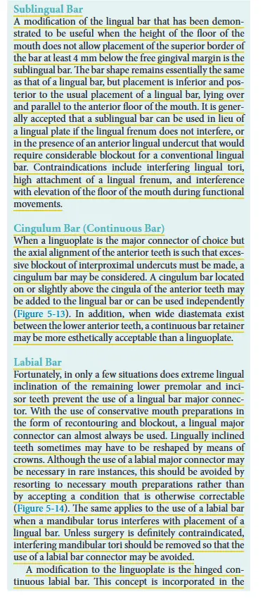 9
9
Sublingual Bar
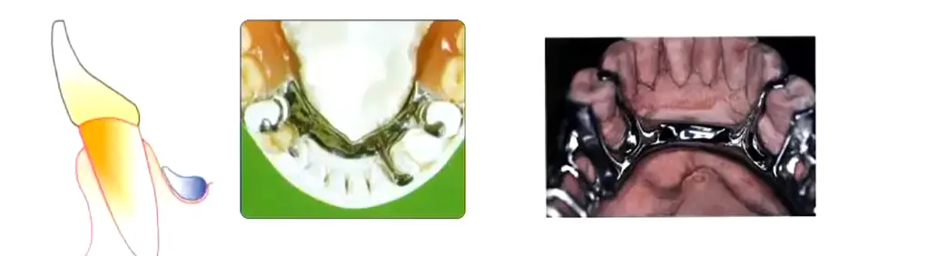
- Shallow floor of mouth
- Lingual undercuts
- Low frenulum attachment
- Lingual tori
- Essentially a lingual bar placed more posteriorly and inferiorly
- Lies over and parallel to the anterior floor of mouth
Double Lingual Bar (Kennedy Bar)
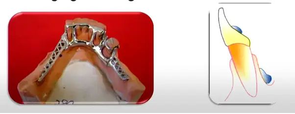
- Standard lingual bar + a secondary bar above the cingula, where additional indirect retention or splinting of periodontally involved teeth is desired
- Across the anterior teeth in Class II/III cases when additional stability is needed but leaving the gingival margins open is desirable410
- Distributes oblique loads across multiple teeth rather than concentrating them on a single rest
- Key advantage vs linguoplate: provides stability while leaving the gingival margins open for self-cleansing10
- Contraindicated where diastemas exist — exposed metal would be visible through the gaps
- Tendency to trap food debris; multiple borders may irritate the tongue
Cingulum Bar (Continuous Bar)
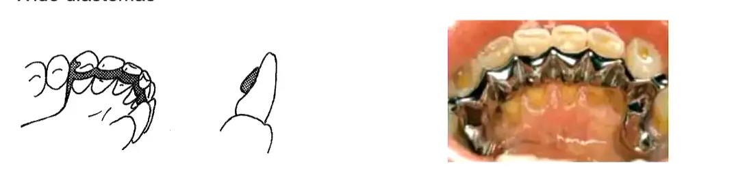
Indications2
- Only when clinical crowns are long enough and no alternative connector is feasible
Drawing tips2
- Contraindicated on retroclined anterior teeth or where wide diastemas are present
Labial Bar (Swing-Lock)
Indications5
- Missing canine
- Unfavourable lingual soft-tissue contour
- Questionable periodontal prognosis
Drawing tips5
- Swing-lock variant incorporates a hinge at one end and a locking mechanism at the other
General Maxillary Design Principles
- All major connectors should cross the midline at right angles for maximum rigidity5211
- Borders kept ≥ 6 mm from the gingival margins in the maxilla, ≥ 3–4 mm in the mandible212; the Denture Adventure workflow uses a practical 3–5 mm rule around gingival margins and around the incisive papilla1011
- Avoid crossing major rugae with the connector border where possible11
- Connector width scales with load: the overall width of a maxillary connector should roughly correspond to the amount of posterior occlusion being replaced411
- Relief is required over the median palatal raphe — the midline suture is prominent and rigid, and settling there causes instability2
- Beading (maxillary exclusive): a 0.5 × 1 mm rounded groove scribed on the master cast along the connector borders, fading out 6 mm from the gingival margin. Prevents food collection and produces a mechanical tissue seal. Narrow bars do not require beading; the clinician must explicitly specify beading to the laboratory. On duplication, the bead line is scored anteriorly and posteriorly but not across the median palatal suture or incisive papilla5211
- Posterior limit of the connector must lie anterior to the vibrating line12
- Relief by Kennedy class: Class III = none or minimal (tooth-supported); Class I, II, IV = moderate (~1.5 mm)12
- Support correlation: the poorer the periodontal support of the remaining teeth, the greater the palatal coverage required2
- Maintain smooth natural palatal contours — decorative rugae-simulation patterns irritate the tongue2
- Long-span anterior modifications may require additional connector thickness or “strengtheners” to prevent midline flexion during function10
Recommended Major Connector by Kennedy Class — quick-reference
| Kennedy Class | Maxillary | Mandibular |
|---|---|---|
| Class I | A-P Palatal Strap (“closed oval” — excellent rigidity) is the academic baseline; Palatal Plate when maximum mucosal support is needed or remaining teeth have a poor prognosis53 | Lingual Bar (standard baseline); Linguoplate or Kennedy Bar when additional indirect retention or splinting of periodontally involved teeth is needed3 |
| Class II | Palatal Strap, A-P Palatal Strap, or Palatal Plate — width scales with the amount of posterior occlusion being replaced4 | Lingual Bar (first choice); Linguoplate (apron) if < 7–8 mm from floor of mouth to gingival margin; Kennedy Bar across the anteriors if extra stability is needed4 |
| Class III | Palatal Strap (the vertical-support workhorse); Single Palatal Bar for a small edentulous span; A-P Palatal Strap when an anterior modification is present1210 | Lingual Bar (standard); Linguoplate/aproning where teeth have a poor prognosis or indirect retention is needed; Kennedy Bar for stability while leaving gingival margins open for self-cleansing10 |
| Class IV | A-P Palatal Strap (closed oval) for standard spans; ==Horseshoe often insufficient for long spans== — escalate to closed-oval A-P strap or Palatal Plate depending on palate depth and mid-palatine raphe prominence126 | Lingual Bar with attention to lingually-inclined posteriors and ridge atrophy; Linguoplate (or interrupted lingual bar with cingulum plating at canines) where vertical resorption is significant6 |
Minor Connectors
- Function: right-angle joint between clasp/saddle and major connector; transmits force; supports the gridwork.
- Gingival margin clearance: maxilla ≥5–6 mm; mandible ≥3–4 mm. Universal 3 mm clearance rule applied when in doubt.
- Mandibular major connectors give NO vertical support — unlike the maxilla (which rests on the hard palate), mandibular connectors only join the framework. Vertical support comes from rests and saddles only.
- Internal (90° butt) vs external (beveled) finish lines: butt joint locks the acrylic mechanically; beveled finish line gives a smoother tissue interface.
Biomechanics & Design Principles
McCracken’s signature lens — every component decision is downstream of these.
Fulcrum line and rotation axes
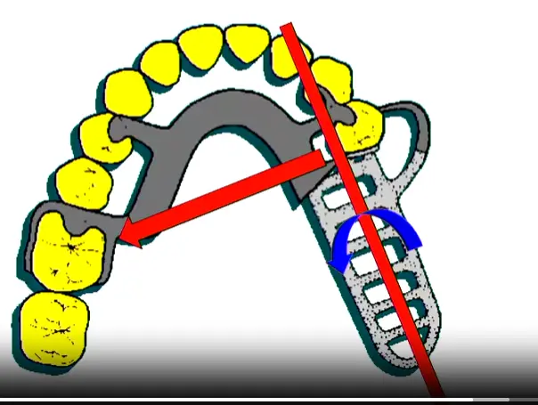
- The fulcrum line passes through the most posterior direct retainers and is the axis around which the prosthesis tries to rotate.
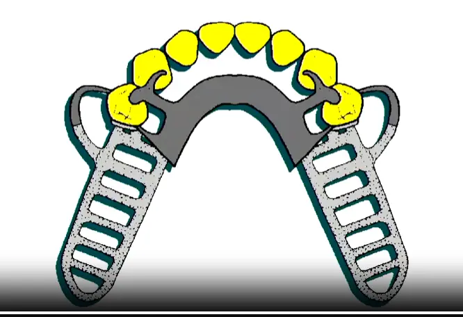
- Class I has up to three fulcrum lines (each posterior abutment, plus both together for sticky-food anterior loading). Indirect retention must address all of them.
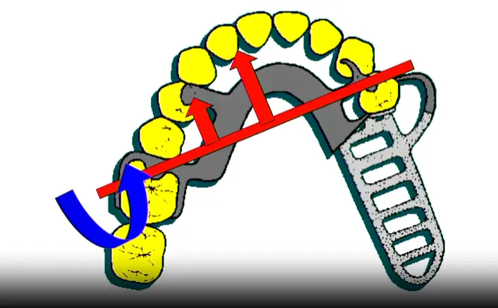
- Class II has shifting fulcrum lines depending on bite location: biting on a buccal cusp lifts opposite side (clasp on intact side resists); biting on the saddle lifts the saddle (rest on the opposite side resists rotation).
| Rotation around posterior abutment | Anti-rotation rest placement | Class I fulcrum geometry |
|---|---|---|
 |  |  |
Stress-breaker philosophy
- A stress-breaker design lets the saddle move under function so the abutment isn’t tortured by lever forces.
- Infrabulge (bar) clasps are the practical embodiment: they disengage from the tooth as the saddle compresses tissue, releasing stress on the abutment.
- Use stress-breakers in Kennedy I/II free-end cases with healthy abutments; favour direct rigid retention in Class III where load goes straight through teeth.
Five core design principles (L10 — recite)
- Maximize support (sufficient rests; broad denture base for tissue support)
- Rigidity (cross-arch transfer; major connector is non-negotiable)
- Bracing (reciprocal arms + minor connectors resist horizontal forces)
- Stability (resists lateral/rotational displacement during function)
- Stress distribution (clasp design, saddle extension, rest placement direct force along long axes)
Class-specific design summary
| Class | Dominant biomechanical concern | Design priorities |
|---|---|---|
| I / II | Saddle rotation under function | Cross-arch rigidity, indirect retention essential, mesial rests, RPI clasps, altered cast for distal extension |
| III | Tooth-supported, simpler kinematics | Rest adjacent to space, indirect retention often optional, focus on hygiene + aesthetics |
| IV | Aesthetics + lip support, anterior leverage | Aesthetic clasps, A-P strap for rigidity, canine guidance, lip support via labial flange |
Three hazards of poor RPD design (L10)
- Caries under clasps and saddles (plaque retention)
- Pathologic tissue change — bone resorption, mucosal hyperplasia, candidiasis
- TMJ dysfunction — from poorly recorded OVD or unbalanced occlusion
Surveying & Design Workflow
Surveyor components and use (L6)
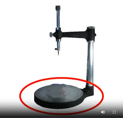
- Vertical column, horizontal arm, surveying arm, analyzing rod, carbon marker, undercut gauges (0.25 / 0.50 / 0.75 mm), surveyor blade (blockout), surveying table, mandrel, wax knife.
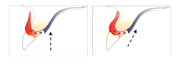
- Carbon-marker technique: use the side of the lead, not the tip — the tip creates a false HOC.
- Three model types: Study (diagnostic survey), Master (final framework cast), Refractory (duplicate for casting investment).
| Surveyor schematic | Carbon-marker side technique |
|---|---|
 |  |
Undercut depth by alloy
| Alloy | Undercut |
|---|---|
| Cobalt-Chromium (CoCr) | 0.25 mm |
| Cast gold | 0.50 mm |
| Stainless steel wire (wrought) | 0.75 mm |
Forcing a CoCr clasp into a 0.75 mm undercut → plastic deformation → permanent retention loss. Always match alloy to undercut depth.
Tilting and HOC techniques
| Technique | When to use | Idea |
|---|---|---|
| Roach (3-point) | Standard starting point | Cast horizontal to a plane defined by the mesial marginal ridges of the molars + proximal contact between centrals (NOT incisal edge) |
| Bisector (Roth) | M-D and B-L inclination needs balancing | Bisects average tilt; fails when teeth have widely varying inclinations |
| Applegate | Best for placing HOC in the middle of clinical crowns | Tilts cast to put HOC between gingival and middle thirds |
Seven-step surveying sequence (L7)
- Preliminary assessment — clinical exam, study models
- Determine path of insertion (POI) — Roach → adjust by Bisector or Applegate as needed
- Mark height of contour (HOC) — carbon marker, side of lead
- Place rests correctly per Kennedy class (mesial in I/II, adjacent in III)
- Mark desired undercuts with the appropriate gauge (CoCr → 0.25 mm)
- Outline the framework — major connector, minor connectors, clasps, saddles
- Adjust contour and prepare guide planes — re-survey after preparation
Tripoding
- Horizontal tripoding — 3 points on horizontal surfaces; transferable between casts (preferred).
- Vertical tripoding — points on vertical surfaces; not transferable.
Soft-tissue and clearance rules
- 3 mm soft-tissue undercut threshold — >3 mm = use suprabulge clasp; ≤3 mm = use infrabulge.
- Infrabulge requires ≥3 mm attached gingivae from free gingival margin to the undercut top.
- 3 mm gingival margin clearance rule for all minor connectors.
- Guide-plane extent: 2/3 of inter-cuspal distance; ≥2/3 of crown height; minimum 2–3 mm vertical.
Survey-only modification vs survey crown
- Conservative recontouring works when the tilt is mild and a workable undercut exists after path optimization.
- A survey crown is required when: severe tilt, no HOC placement that yields adequate undercut, or marginal ridge needs to be rebuilt for rest seat support.
Drawing the Design — Step-by-Step
The drawing workflow has two parallel tracks: the L7 7-step surveying sequence (above) tells you what the cast will physically engage; the Denture Adventure 4-step design framework (below) tells you what to draw, in what order. Run them together — survey first, then draw on the cast.
The 4-Step Design Framework (Denture Adventure — applies to every Kennedy class)
| # | Step | What you do |
|---|---|---|
| 1 | Outline edentulous areas | Mark every edentulous space and decide the retention method (mesh lattice for acrylic; metal backing/posts for low VDO) |
| 2 | Identify direct retainers | Pick the abutment teeth adjacent to each edentulous area; choose the clasp type per Kennedy class |
| 3 | Auxiliary rests + indirect retention | Locate the fulcrum line; place rests perpendicular to it and as far from it as possible |
| 4 | Major connector | Connect all components with the appropriate connector; verify 90° midline crossing and gingival clearance |
Crosswalk — surveying ↔ drawing
| Surveying step (L7) | Drawing decision it unlocks | What appears on the cast |
|---|---|---|
| 1. Preliminary visual | Kennedy class, fulcrum line(s), abutment quality | Vertical black lines marking candidate rest seats |
| 2. Path of insertion (Roach → Bisector → Applegate as needed) | All subsequent geometry | Wax block reference on edentulous side if landmarks missing |
| 3. Height of contour (carbon marker, side of lead) | Above HOC = reciprocal/connector; below HOC = retentive arm | HOC line drawn on each abutment |
| 4. Rest position | Step 1 + Step 3 of the 4-step framework | Rests sketched: adjacent (Class III), mesial (Class I/II), distal of canine (Class IV) |
| 5. Desired undercut (0.25 mm CoCr gauge) | Clasp tip terminal-third location | Undercut dot on each abutment |
| 6. Framework outline | Whole 4-step framework on paper | Major + minor connectors, clasps, rests, mesh, finish lines |
| 7. Adjust HOC + guide planes | Where the framework can actually seat | Trimmed contour + parallel guide-plane preparations |
Practical sequence on the cast
Draw lightly in pencil first → verify on the surveyor → ink only after every component passes the survey. The 4-step framework is iterative, not linear: once you’ve drawn the major connector, re-verify that all minor connectors land at right angles to it and clear the gingiva by 3 mm.
Per-Class Drawing Playbook
Kennedy Class I — bilateral free-ends (see Cast Partial Denture Design Kennedy Class I)
Mandibular
- Mesh extends distally to the 1st molar area; acrylic covers retromolar pads
- Tissue stops on the midline of each ridge to support the free-end
- Direct retainers (stress-breaking — mandatory): RPI (preferred), RPA, Roach/I-bar, or G-clasp on terminal abutments (e.g., 34, 44)
- Mesio-occlusal rests on terminal abutments — direct forces vertically, prevent distal tipping
- Wrought-wire option (SS, gold, Pt-Au-Pd) for added flexibility on compromised abutments
- Fulcrum line: through the two most distal rests
- Indirect retention: cingulum rests on canines (33, 43) — perpendicular to the midpoint of the fulcrum line. Incisors are closer to the perpendicular but typically have insufficient C:R ratio
- Major connector: lingual bar (academic baseline). Switch to Kennedy bar / lingual plate if perio compromise or future tooth loss is anticipated
Maxillary
- Direct retainers on 15, 25 — G-clasps or Roach clasps
- Indirect retention on canines (13, 23) — cingulum rests
- Major connector: A-P palatal strap (closed oval) is the academic baseline for excellent rigidity; full palate when maximum mucosal support is needed or remaining teeth are guarded
- Modification 1 (anterior space): rests on both sides of the modification space to close off guide planes; mesh + posts (or metal backing if VDO is tight)
Kennedy Class II — unilateral free-end (see Cast Partial Denture Design Kennedy Class II)
- Free-end side: stress-breaker (RPI / RPY / Roach) on the tooth immediately anterior to the space; aesthetic-zone canines need careful HOC and undercut measurement to hide the clasp
- Dentate side: one clasp as far anterior + one as far posterior as possible. Simple Akers (circlet) clasps are usually optimal. Avoid embrasure clasps in this role — they create a tripod, which is less stable than spread-out support
- Fulcrum line: through the most distal rest on each side
- Indirect retention: cingulum rest on canine OR occlusal rest on a contralateral 1st premolar — placed ~90° from the fulcrum line. Maxillary preference: premolar over canine (avoids interference with canine-guided lateral movements)
- Modification spaces: aim for tripod/quadrilateral rest distribution
- Pier abutments (lone bicuspid): often best negated in the design (guide planes only, no rests) to prevent the tooth from acting as a pivot
- Plating / Kennedy Bar across anteriors when extra stability is needed
Kennedy Class III — bounded edentulous (see Cast Partial Denture Design Kennedy Class III / DENT1158 Project 4 Design Survey Blockout)
- Tooth-borne appliance — no rotation lines, no dislodgement issues. Indirect retention generally not required
- Trapezoidal 4-rest configuration is significantly more stable than a tripod. Split clasps (one far anterior + one far posterior) instead of an embrasure clasp where possible
- Future-proofing: if a posterior molar has guarded prognosis, place an anterior rest (canine/premolar) during the initial design — the framework converts to a Class II seamlessly if the molar is lost, no remake needed
- Anterior modification: at minimum a cingulum or mesio-lingual rest on each tooth bordering the space; strengthen the major connector for long-span anterior modifications to prevent midline flexion
- Pier abutments: window the metal around them for self-cleansing, OR plate them if loss is anticipated; if used as abutment, mesial AND distal rests required
- Aesthetic single tooth: bar clasps (I-bar / Roach) over circumferential to minimize metal display
- Mandibular major connector: lingual bar; switch to apron / Kennedy bar for poor prognosis or hygiene priorities
- Maxillary major connector: palatal strap (workhorse); single palatal bar for small spans; A-P strap when an anterior modification is present
Kennedy Class IV — anterior crossing midline (see Cast Partial Denture Design Kennedy Class IV)
- Manage anterior rotation/leverage — this is the dominant biomechanical concern
- Clasp strategy (strong preference for Trapezoidal over Embrasure):
| Strategy | Description | Trade-off |
|---|---|---|
| Embrasure clasping | Clasps on teeth immediately adjacent to the space (e.g., 5–6) | Simple but high A-P rotation risk; relies on clasp tightness |
| Trapezoidal design (preferred) | Clasps as far anterior + as far posterior as possible (e.g., 4 and 7) | More stable, larger statics surface; more metal, more prep |
- Long-span Class IV (pseudo-Class V, 6–8 anterior missing):
- Behaves as a reverse Class I — rotation line through the two most anterior rests
- Indirect retention as far posterior as possible
- Horseshoe usually insufficient — escalate to closed-oval A-P palatal strap or full palatal plate depending on palate depth and mid-palatine raphe prominence
- G-clasp on the most posterior molars
- Two-molars-only scenario (common design trap):
- Akers fallacy: a standard Akers clasp won’t engage when the anterior section lifts — the denture rotates into tissue
- Solution: ring clasp that engages mesio-lingual or mesio-buccal undercut to actually resist lift
- Strong implant indication
- Mandibular Class IV:
- Anterior teeth often 7–12 mm long due to ridge atrophy → use posts, not just mesh
- Lingual bar relief — atrophied posterior ridges with lingual inclination push the bar 3–4 mm off tissue → food trap → consider interrupted lingual bar with cingulum rests/plating at canines
Drawing & Blockout — Practical Tips (from DENT1158 Project 4 Design Survey Blockout)
Tripoding the model
- X-axis method — mark x-axis on sides + back of base
- 3-point method — three widely-spaced “bullseye” circles (~3 mm) on the tissue surface
Blockout
- Proximal surfaces: wax below the HOC on all abutments; parallel to POI with the analyzing rod
- Free gingival margins: light blockout to prevent metal impingement
- Ledge at the survey line for Akers clasps (sharp wax ledge guides the wax pattern). Do NOT ledge guide planes or wrought-wire areas
- Horizontal shoe extensions: 0.6 mm wax extensions distal to canines and mesial to molars → clean acrylic-to-metal internal finishing line
- Bead line (maxillary only): faint score at anterior + posterior major-connector borders, fading 6 mm from gingival margins; AVOID crossing the median palatal suture or incisive papilla
Drawing geometry — universal rules
| Element | Specification |
|---|---|
| Major connector midline crossing | 90° always — never oblique |
| Maxillary connector clearance from gingival margin | ≥6 mm (textbook); 3–5 mm acceptable in practice |
| Mandibular connector clearance from gingival margin | 3–4 mm |
| Major connector minimum width (strap) | ≥8 mm |
| Lingual bar vertical space | 8 mm total = 5 mm bar height + 3 mm clearance |
| Posterior maxillary connector limit | Anterior to vibrating line |
| Universal minor connector gingival clearance | 3 mm |
| Guide-plane extent | 2/3 inter-cuspal distance; ≥2/3 crown height; minimum 2–3 mm |
| Free-end saddle ridge coverage | 2/3 of the ridge |
| CoCr undercut depth | 0.25 mm |
| Cast gold undercut depth | 0.50 mm |
| Wrought wire undercut depth | 0.75 mm (e.g., canine in Project 4) |
| Bead-line groove dimensions | 0.5 × 1 mm rounded, fades 6 mm from gingival margin |
| Tissue undercut threshold for infrabulge clasp | ≤3 mm soft-tissue undercut + ≥3 mm attached gingivae |
Five universal design rules (from McCracken Ch 10 “Principles of RPD Design”)
- Symmetry — balanced arch form, not straight lines
- Simplicity — simplest clasp that satisfies the requirements
- Future planning — design the framework so additional teeth can be added to the acrylic later
- Load reduction — not replacing a 2nd molar reduces the lever arm on the terminal abutment
- Verify — re-survey after every modification; confirm undercuts are real, not artifacts of trimming
Clinical Workflow
Mouth preparation phases (L8)
| Phase | Components | Must finish before next phase? |
|---|---|---|
| Control | Periodontal therapy, endo, restorative, surgery, ortho, occlusal adjustment | Yes — verified by reduced BoP and probing depth |
| Holding (optional) | Reassessment of compliance and tissue health | — |
| Reconstructive (Biomechanical) | Rest seats, guide planes, contour modification, survey crowns | Final step before master impression |
OCHWA endo abutment protocol
Per R1 OCHWA guideliens for RPD and endotreated teeth:
- Recent RCT, no radiolucency → wait for bone formation
- Old RCT with radiolucency → percussion test; consider retreatment
- RCTs done outside OCHWA on a planned RPD abutment → offer retreatment first, even if the treatment appears adequate. This protects against latent failure once the tooth is loaded as an abutment.
Restorability rules
- Ferrule rule: 360° ideal; partial buccal-lingual may suffice if combined with ferrule preservation in the rest area.
- Rest-in-amalgam rule: ≥1 mm of intact amalgam under and around the rest seat. If the seat would cross a tooth-restoration interface, replace the restoration first before preparing the seat.
Duralay transfer guide essentials
- Apply separator (NOT Vaseline) to the master cast
- Build ≥5 mm acrylic block over the abutment
- Trim parallel to the planned POI on the surveyor
- Cement chairside with zinc phosphate — not GIC, so the guide can be removed cleanly after preparation
Full clinical-laboratory sequence (L9)
| # | Clinical step | Lab step | Key check |
|---|---|---|---|
| 1 | History + diagnostic exam | — | Identify Kennedy class, classify support type |
| 2 | Study models + face-bow record | Mount on articulator | Diagnostic wax-up identifies survey crowns |
| 3 | Mouth preparation (Control + Reconstructive) | — | Verify BoP/PD reductions; rest seats prepared last |
| 4 | Final elastomeric impression | Pour master model + duplicate | Refractory cast for casting |
| 5 | Framework casting | — | — |
| 6 | Framework try-in | — | Passive seating, no rocking, retention/stability; tissue side smooth (not polished) |
| 7 | MMR (max-mand record) | — | OVD via freeway space, verified by closest speaking space; CR via leaf gauge |
| 8 | Altered cast (mandibular Kennedy I/II only) | Re-pour distal-extension portion | Finger pressure on rests only, never the saddle |
| 9 | Tooth try-in (wax) | — | Aesthetics, occlusion, neutral zone |
| 10 | Processing | Acrylic flask + cure | — |
| 11 | Insertion | — | Pressure-indicating paste; check terminal-third never-adjust; trim overextensions; fit-checker spray for voids |
| 12 | Review (24 h, 1 wk, 1 mo) | — | Reline if tissue fitting surface gaps appear |
MMR specifics
- OVD = RVD − freeway space (average freeway 3 mm). Verify with closest speaking space (“Mississippi 66” — sibilants should not click).
- Centric relation via leaf gauge: each leaf = 200 µm. Avoid pushing past the comfortable retruded position. Use an anterior jig if TMD symptoms are present.
- Altered cast is only indicated for mandibular Kennedy I/II — never for the maxilla (the palate already provides functional ridge form) and never for Class III (tooth-supported, no compression).
Insertion defect management
| Defect | Action |
|---|---|
| Voids / porosity in acrylic | Return to lab |
| Sharp nodules / projections | Adjust chairside with carbide bur |
| Overextension | Trim to neutral zone |
| Fit-checker spray reveals tissue contact gap | Reline |
Reline protocol
- PVS or ZOE wash; finger pressure on rests only — never on the saddle (saddle pressure compresses tissue and gives a false fit).
- Take a pickup impression in alginate (after re-recording the bite if needed).
Neutral zone
- Defined by the balance between tongue forces and circumoral musculature forces. Teeth placed outside it cause instability and soft-tissue trauma.
Key Lectures
- L1 Introduction to RPD — rationale, RPD vs FPD, Ante’s Law, Combination Syndrome
- L2 Components and Classifications — seven components, Kennedy + Applegate, support types
- L3 Rests and Rest Seats — morphology, dimensions, placement by class
- L4 Clasp Assembly — six requirements, clasp types, RPI, guide planes
- L5 Major and Minor Connectors — rigidity, gingival clearance, selection by case
- L6 Dental Surveyor — equipment, carbon-marker technique, undercut gauges, tilting techniques
- L7 Survey and Design — 7-step sequence, fulcrum line, undercut thresholds, tripoding
- L8 Mouth preparation for RPD — Control vs Reconstructive, Duralay, OCHWA endo rule
- L9 Clinical Sequence — full workflow, MMR, altered cast, insertion defects
- L10 RPDs Summary — five core principles, three hazards, class-specific rules
- LOs — master learning objectives checklist
Related Resources
Mental Dental video series
- Prosthodontics - 10 - Kennedy Classification
- Prosthodontics - 11 - Major & Minor Connectors
- Prosthodontics - 12 - Rests & Proximal Plates
- Prosthodontics - 13 - Clasp Design & Selection
Kennedy-class design references
- Cast Partial Denture Design Kennedy Class I
- Cast Partial Denture Design Kennedy Class II
- Cast Partial Denture Design Kennedy Class III
- Cast Partial Denture Design Kennedy Class IV
Surveying resources
Denture fit & troubleshooting
OCHWA / regulatory
Related Procedures
- No dedicated RPD procedure notes exist yet in
Reference/Prosthodontics/Procedures/— see L8 Mouth preparation for RPD and L9 Clinical Sequence for clinical sequencing, and the Kennedy-class design files in Related Resources.
Sources / Notes
- McCracken’s Removable Partial Prosthodontics - E-Book Annotations
- McCracken’s Removable Partial Prosthodontics - E-Book TOC
- McCracken’s Removable Partial Prosthodontics, 14e — Carr & Brown
- DMD3S1 Removable Partial Dentures (UWA) lecture series — Dr. Marrwa Ibrahim
Footnotes
-
L5 Major and Minor Connectors ↩ ↩2 ↩3 ↩4 ↩5 ↩6 ↩7 ↩8 ↩9 ↩10 ↩11 ↩12 ↩13 ↩14 ↩15
-
General Principles for Mandibular Design ↩ ↩2 ↩3 ↩4 ↩5 ↩6 ↩7 ↩8 ↩9 ↩10 ↩11 ↩12 ↩13 ↩14 ↩15 ↩16 ↩17 ↩18 ↩19 ↩20 ↩21 ↩22 ↩23 ↩24 ↩25
-
Cast Partial Denture Design Kennedy Class II ↩ ↩2 ↩3 ↩4 ↩5 ↩6 ↩7 ↩8
-
Prosthodontics - 11 - Major & Minor Connectors ↩ ↩2 ↩3 ↩4 ↩5 ↩6 ↩7 ↩8 ↩9 ↩10
-
Cast Partial Denture Design Kennedy Class IV ↩ ↩2 ↩3 ↩4 ↩5 ↩6
-
ROLE OF MAJOR CONNECTORS IN CONTROL OF PROSTHESIS MOVEMENT > Mandibular Major Connectors > Lingual Bar ↩
-
ROLE OF MAJOR CONNECTORS IN CONTROL OF PROSTHESIS MOVEMENT > Mandibular Major Connectors > Design of Mandibular Major Connectors ↩
-
Cast Partial Denture Design Kennedy Class III ↩ ↩2 ↩3 ↩4 ↩5 ↩6 ↩7 ↩8