Cast Partial Denture Design Kennedy Class II
Kennedy Class II Removable Partial Denture Design

This document outlines the systematic approach to designing Kennedy Class II (unilateral free-end edentulous space) Removable Partial Dentures (RPDs). The following protocols emphasize the four-step design process, clinical considerations, and the rules of indirect retention.
The Four-Step Design Process
To ensure a consistent and functional result, every RPD design should follow these four logical steps:
- **Outline Edentulous Areas:
 ** Identify the unilateral free-end space and any modification spaces. Determine the method of attachment (e.g., mesh lattice retention with internal/external finishing lines).
2. **Identify Direct Retainers:
** Identify the unilateral free-end space and any modification spaces. Determine the method of attachment (e.g., mesh lattice retention with internal/external finishing lines).
2. **Identify Direct Retainers:
 ** Select the primary abutment teeth adjacent to the edentulous areas.
3. **Determine Auxiliary Rests and Indirect Retention:
** Select the primary abutment teeth adjacent to the edentulous areas.
3. **Determine Auxiliary Rests and Indirect Retention:
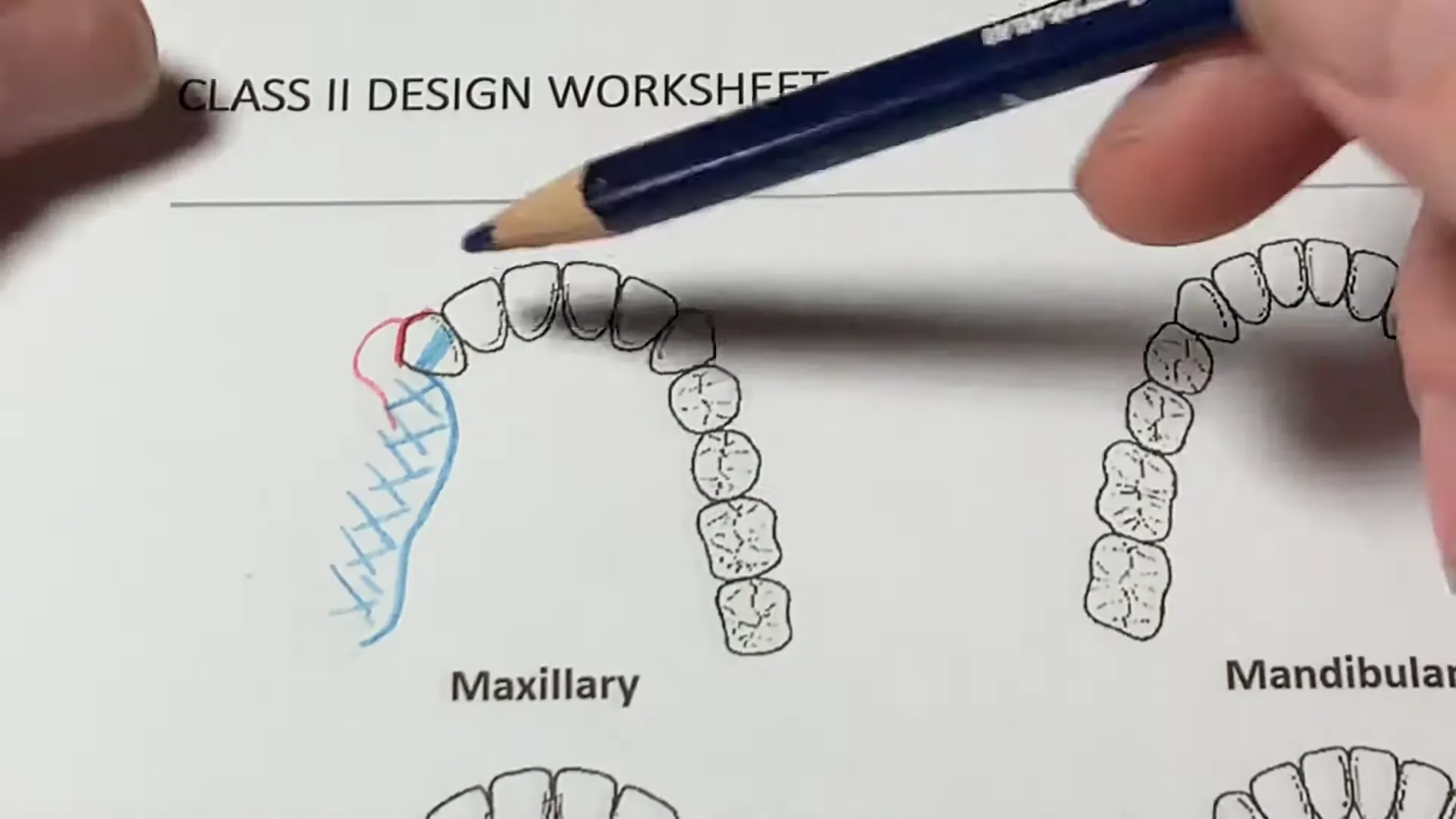 ** Locate the fulcrum line and place rests to prevent the denture base from lifting.
4. **Connect the Major Connector:
** Locate the fulcrum line and place rests to prevent the denture base from lifting.
4. **Connect the Major Connector:
 ** Join the components using the appropriate maxillary or mandibular major connector.
Design Principles for Kennedy Class II Cases
1. Direct Retention and Stress Breaking
For the primary abutment tooth (typically the tooth immediately anterior to the free-end space), a stress-breaking clasp is essential to protect the tooth from excessive torque.
- Clasp Options: RPI, RPY, or Roach (G) clasps
 .
.
- Materials: Ticonium, wrought wire, gold, or palladium are all acceptable depending on the clinical need.
- Aesthetics: In the “aesthetic zone” (e.g., maxillary canines), the height of contour and tissue undercut must be carefully measured to hide the clasp assembly in the buccal-labial sulcus.
2. The Dentate (Opposing) Side
On the side of the arch without a free-end, the goal is to provide stability and retention without compromising the health of the teeth.
- Clasping Strategy: Place one clasp as far anterior as possible and one as far posterior as possible (e.g., an embrasure clasp on the molars).
- Clasp Type: Simple Akers (circlet) clasps are often the most effective for these areas
 .
.
3. Indirect Retention
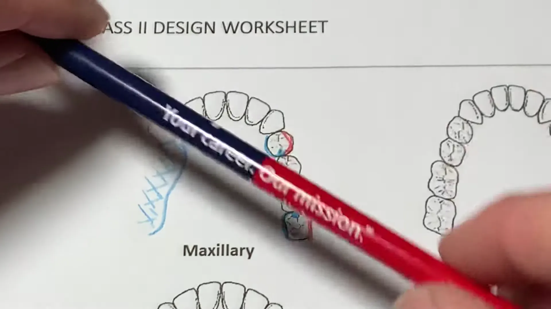
The fulcrum line in a Class II case runs through the most distal rests. To prevent the denture base from lifting away from the tissue:
- Placement: Indirect retainers should be placed as far from the fulcrum line as possible, usually 90 degrees to the line.
- Common Locations: Cingulum rests on canines or occlusal rests on first premolars
 .
.
- Enhancements: If additional stability is needed, “plating” or a “Kennedy Bar” (double lingual bar) can be used across the anterior teeth
 .
.
Clinical Considerations and Prognosis
A design on paper must be tempered by clinical realities. The following factors frequently necessitate design modifications:
| Factor | Impact on Design |
|---|---|
| Opposing Dentition | Whether the patient has natural teeth, a bridge, or a complete denture dictates the occlusal load. |
| Vertical Dimension (VDO) | Limited inter-occlusal space may prevent the use of certain rests or minor connectors. |
| Restorative History | Teeth with heavy restorations, endodontic treatment, or full gold crowns may have a “guarded” prognosis as abutments. |
| Patient Expectations | Previous experience with prosthetics and aesthetic concerns (the “vanity factor”) influence clasp selection. |
| Anatomy | A shallow floor of the mouth or a strong lingual frenum may preclude a lingual bar, requiring a lingual plate instead. |

Specific Case Scenarios
Modification Spaces
When a Class II case includes a modification space (an edentulous gap on the otherwise dentate side), the teeth adjacent to that gap act as additional abutments.
- Static Design: Aim for a “tripod” or “quadrilateral” distribution of rests to create a stable “scaling triangle” of support
 .
.
- Pier Abutments: Freestanding teeth (e.g., a lone bicuspid) within a space can be problematic. They often act as pivot points. It is sometimes prudent to “negate” these in the design—treating them with guide planes but no rests—to avoid premature loss of the tooth
.
Maxillary vs. Mandibular Connectors
- Maxillary: Options include a palatal strap, an anterior-posterior (A-P) palatal strap, or a full palatal plate. The width of the connector should generally correspond to the amount of posterior occlusion being replaced
 .
.
- Mandibular: The lingual bar is the first choice. If there is insufficient room (less than 7-8mm from the floor of the mouth to the gingival margin), a lingual plate (apron) is required
 .
.
Summary of Design Rules
- Symmetry: Avoid straight lines; try to balance the arch form.
- Simplicity: Use the simplest clasp form that satisfies the requirements.
- Future Planning: Design with the future in mind. If a tooth has a poor prognosis, design the framework so that a replacement tooth can be easily added to the acrylic base later.
- Load Reduction: Reducing the occlusal table (e.g., not replacing the second molar) can reduce the lever-arm effect and stress on the terminal abutment
.