Dental Surveyor
The primary objectives for studying the dental surveyor include:
Learning Outcomes1
- Discuss the aim of using a dental surveyor.
- Describe all components of a surveyor.
- Discuss how the surveyor is used for the fabrication of a Cobalt-Chrome (Co-Cr) Removable Partial Denture (RPD).
- Describe three different techniques to establish the ideal path of insertion of an RPD.
Definition2
A dental surveyor is a paralleling instrument used to determine the relative parallelism of two or more tooth surfaces.
According to the Glossary of Prosthodontic Terms (GPT), it is an instrument used to locate and delineate the contours and relative positions of abutment teeth and associated structures.
It is utilized to:
- Select the most favorable path of insertion.
- Aid in the preparation of guiding planes.
The dental surveyor consists of several specialized components designed for precision measurement and marking of dental casts.
Parts of a Dental Surveyor34
The primary structural components of the dental surveyor include:
Surveying Platform5
The base upon which the assembly rests.
- Keep this surface clean to ensure accurate surveying as it remains parallel to the bench top.
- 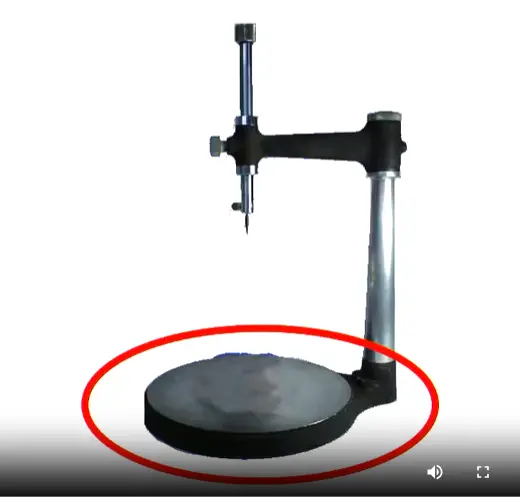
- Vertical column: Supports the upper assembly.
- Horizontal arm: Extends from the column to position the surveying tools.
- Surveying arm: The vertical moving part that holds the tools.
- Mandrel: The chuck or attachment point for various surveying tools.
The surveying table is used to:
- Hold the dental cast securely in place.
- Adjust the tilt of the cast using a ball-and-socket joint.
Cast Preparation and Stability
The cast must be properly trimmed before surveying to ensure stability. The base and back must be completely flat and parallel to the occlusal plane. If the technician has not trimmed it properly, you must trim it in the plaster room; any movement during surveying will completely compromise the surveying line.
Surveying Table6
The assembly allows for the stabilization of the dental cast while various diagnostic and technical procedures are performed.
Analyzing Rod
Surveying Tools7
The analyzing rod is used to:
- Determine the relative parallelism of axial surfaces.
- Analyze contours and undercut areas without leaving marks on the cast.
- The analyzing rod is very thin and can bend if the model hits against it; once bent, it cannot be restored to parallel and becomes useless.
The carbon marker is used to mark the height of contour (survey line) of teeth on the surfaces of the dental cast. - Critical Technique: Use the side of the carbon marker, not the tip, to avoid creating a false height of contour. - Any point along this line represents the most protruded point of that surface.
Carbon Marker8
Undercut gauges are used to identify the specific position and depth of desired undercuts on the dental casts.
Undercut Gauges9
The surveyor blade is used to trim the stone tooth on the cast to adjust the height of contour to a more desirable position. - This allows the clinician to determine exactly how much tooth structure must be removed to create proper guide planes on tilted teeth.
Surveyor Blade10
The wax knife is utilized during:
- Blockout procedures for cutting and shaping wax.
- The construction of surveyed restorations, such as preparing guiding planes.
Wax Knife11
Functions of the Surveyor12131415
Determining the most favorable path of insertion involves evaluating several factors:
Determine the Most Favorable Path of Insertion16
- Presence of suitable undercuts for retention.
- Elimination of hard and soft tissue interferences.
- Creation of desirable aesthetics.
- Establishment of appropriate guiding planes.
- Aesthetics: Position clasps to engage the middle or cervical third of the tooth, never the occlusal third to avoid metal visibility and occlusal interference.
- Avoiding Displacement: Tilt the cast so the path of insertion is not aligned with the direction sticky food would pull the denture.
Identification of Interferences
The surveyor is used to identify anatomical or structural obstacles that may impede the path of insertion for a prosthesis.
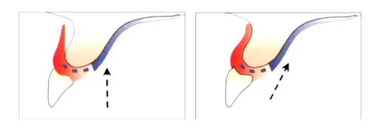
Case Study: Soft Tissue Undercut Interference
If the path of insertion creates an undercut in the soft tissue, the denture cannot seat properly. Solutions include altering the path of insertion to eliminate the undercut, rather than using blockout which results in a loss of tissue contact/seal.
Common Anatomical Interferences
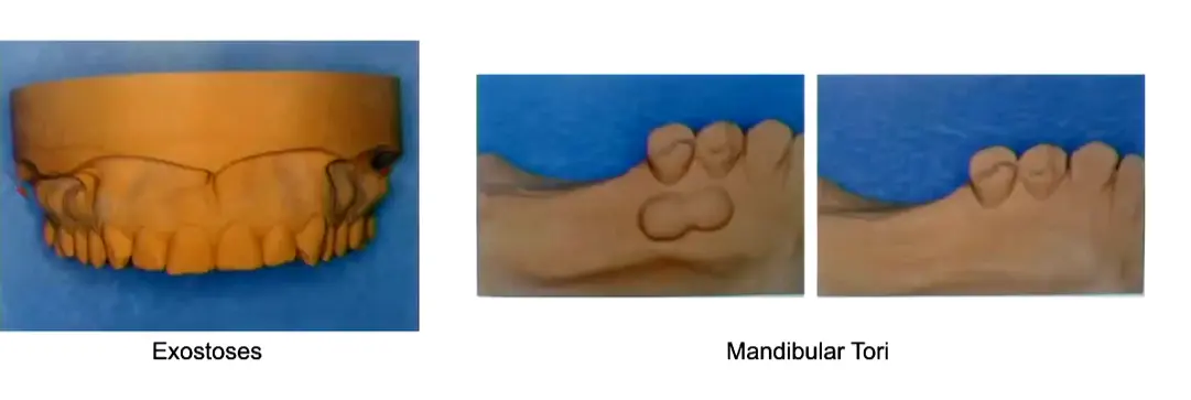
- Exostoses: Bony outgrowths that can interfere with the denture base.
- Mandibular Tori: Bony protuberances on the lingual aspect of the mandible that may require relief or surgical removal.
Evaluation of the cast continues to ensure all potential path-of-insertion obstacles are accounted for.
The surveyor uses a carbon marker to identify the height of contour.
Delineate the Height of Contour of Supporting Teeth17
- True height of contour: The actual widest part of the tooth relative to the path of insertion.
- False height of contour: An incorrect marking, often caused by the carbon marker being positioned too high on the tooth or using an incorrect tool angle.
The surveyor determines specific undercut depths required for different materials:
Determine Areas for Denture Retention18
- 0.25 mm (0.01 inch): Used for Cobalt-Chrome (CoCr) alloys.
- 0.50 mm (0.02 inch): Used for Cast gold.
- 0.75 mm (0.03 inch): Used for Stainless steel wire
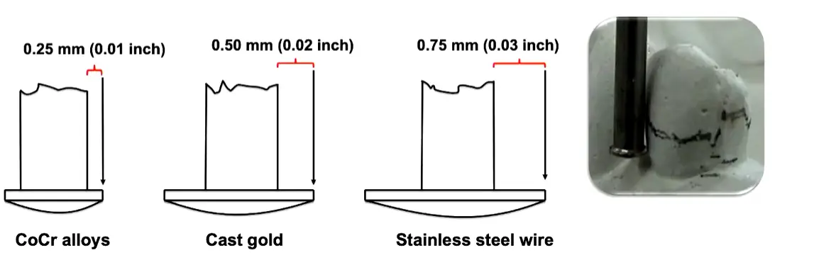
Case Study: Exceeding the Elastic Limit
If a stiff alloy like cobalt chrome is used in a deep 0.75mm undercut, repeated insertion exceeds the elastic limit, causing plastic deformation. The clasp permanently bends, and retention is lost. Clinically bending it back is only a temporary fix; the framework must be designed for the correct undercut depth.
Material Considerations
Different alloys have different moduli of elasticity. Cobalt chrome is the most rigid and engages the shallowest undercut (0.25mm), while Gold is the most flexible and can engage the deepest (0.75mm). For periodontally compromised teeth, wrought wire (0.5mm) is preferred as its elasticity places less load on the tooth. .
The surveyor identifies proximal tooth surfaces that are parallel to act as guiding planes during placement and removal. If no parallel walls are naturally available, the supporting teeth contours must be adjusted to create parallel interproximal surfaces.
Identify Guiding Planes on Proximal Tooth Surfaces19
Guiding Plane Verification
Continued analysis of proximal surfaces ensures the path of placement is stabilized by parallel guiding planes.
The surveyor assists in the relief of the master cast by shaping and cutting wax during block-out procedures to eliminate unwanted undercuts. - Three Model Types: Study Model (initial assessment), Master Model (from PVS impression after mouth prep), and Cast/Refractory Model (duplicate of blocked-out master model for framework fabrication).
Assist in Blockout Procedures20
The instrument is used for the precise placement of both internal and external precision attachments.
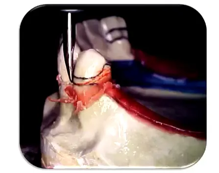
Placement of Precision Attachments21
The surveyor is used in the technical preparation of surveyed crowns to ensure they conform to the planned path of insertion and provide necessary retention/reciprocation features.
Preparation of Surveyed Crowns22
The surveyor guides the clinician in determining necessary mouth preparations, such as recontouring or rest seat placement, prior to final impressions.
Assist Mouth Preparation23
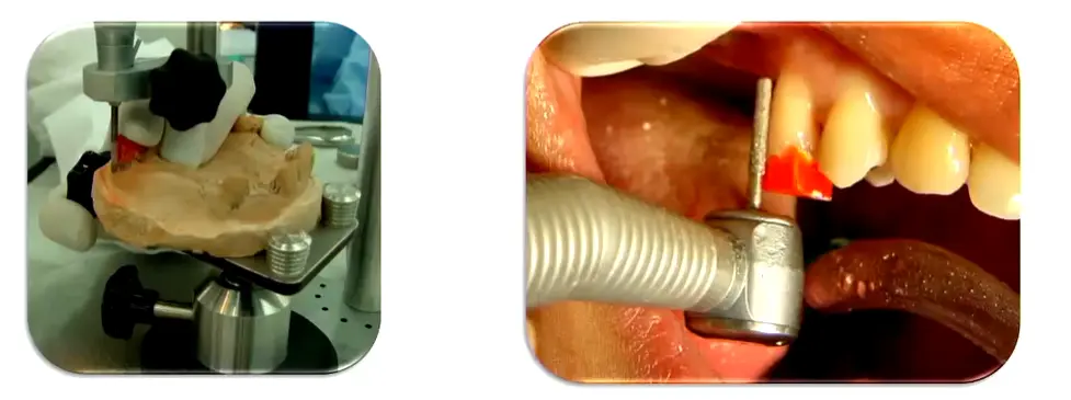
Path of Placement Techniques242526
There are three primary techniques used to determine the path of placement:
- Roach technique
- Bisector (or Roth) technique
- Applegate technique
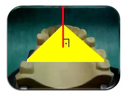
Roach Technique27
The path of placement is set perpendicular to an insertion plane (occlusal plane), which is defined by three points on the model. - Reference Points: Posteriorly use the mesial marginal ridges of molars; anteriorly use the proximal contact point between incisors (not the incisal edge). - Limitation: If a tooth is overerupted, do not follow it; plan for a surveying crown instead.
- Limitation: The long axes of the teeth are often not perpendicular to the occlusal plane, which may lead to poor results.
 The path of placement is determined by the average inclination of the supporting teeth, considering both:
Bisector or Roth Technique28
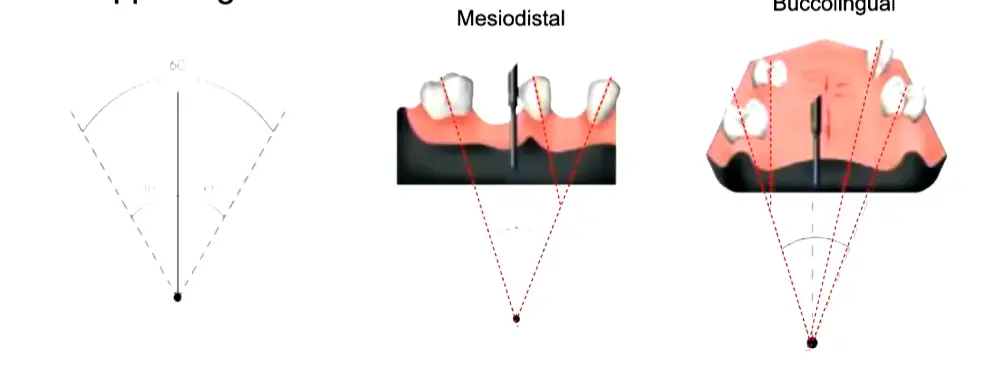
- avg of the inclination of both techniques
Bisector or Roth Technique Limitations
- Limitation: This technique becomes increasingly difficult to apply when there are multiple supporting teeth with varying inclinations.
Applegate Technique29
This technique establishes the best incline of the cast where the height of contour of the supporting teeth is located between the gingival and middle thirds, or the position that most favors mouth preparation.
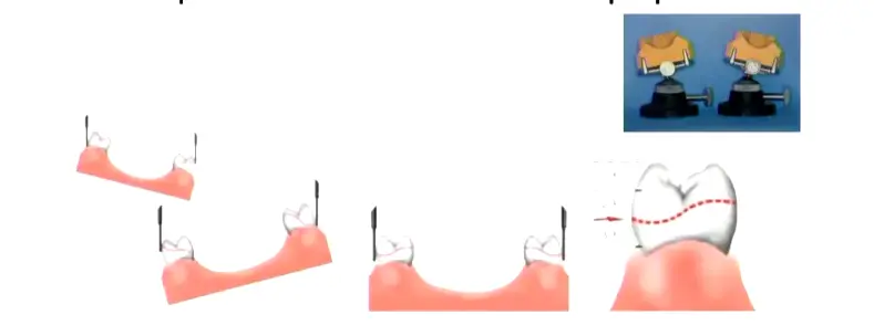
Applegate Technique Limitations
- Operator experience: Requires significant clinical judgment.
- Previous planning: Success depends heavily on thorough initial case analysis.
- Clinical Recommendation: The ideal approach is a mix of the Roach and Applegate techniques, using Roach for initial assessment and Applegate for final refinement.
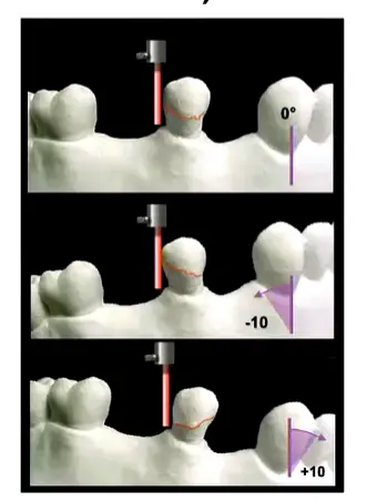
- Clinical Recommendation: The ideal approach is a mix of the Roach and Applegate techniques, using Roach for initial assessment and Applegate for final refinement.
Digital Surveying with 3Shape CAD Software and Scanner303132
Modern surveying can be performed digitally using 3Shape CAD software and scanners to analyze casts and plan RPD frameworks.
Digital workflows allow for precise identification of undercuts and path of insertion through virtual modeling.
The integration of CAD software streamlines the transition from diagnostic surveying to the manufacturing of the Cobalt-Chrome framework. - Current Standard: Traditional casting remains the standard as CAD/CAM milling of chrome blocks is not yet cost-effective. - 3D Printing: Currently used to print resin patterns for casting, but direct metal printing is not yet standard for complex RPDs.
Footnotes
-
Original PDF page 2: L6 Dental Surveyor, p.2 ↩
-
Original PDF page 3: L6 Dental Surveyor, p.3 ↩
-
Original PDF page 4: L6 Dental Surveyor, p.4 ↩
-
Original PDF page 7: L6 Dental Surveyor, p.7 ↩
-
Original PDF page 5: L6 Dental Surveyor, p.5 ↩
-
Original PDF page 6: L6 Dental Surveyor, p.6 ↩
-
Original PDF page 8: L6 Dental Surveyor, p.8 ↩
-
Original PDF page 9: L6 Dental Surveyor, p.9 ↩
-
Original PDF page 10: L6 Dental Surveyor, p.10 ↩
-
Original PDF page 11: L6 Dental Surveyor, p.11 ↩
-
Original PDF page 12: L6 Dental Surveyor, p.12 ↩
-
Original PDF page 14: L6 Dental Surveyor, p.14 ↩
-
Original PDF page 15: L6 Dental Surveyor, p.15 ↩
-
Original PDF page 16: L6 Dental Surveyor, p.16 ↩
-
Original PDF page 20: L6 Dental Surveyor, p.20 ↩
-
Original PDF page 13: L6 Dental Surveyor, p.13 ↩
-
Original PDF page 17: L6 Dental Surveyor, p.17 ↩
-
Original PDF page 18: L6 Dental Surveyor, p.18 ↩
-
Original PDF page 19: L6 Dental Surveyor, p.19 ↩
-
Original PDF page 21: L6 Dental Surveyor, p.21 ↩
-
Original PDF page 22: L6 Dental Surveyor, p.22 ↩
-
Original PDF page 23: L6 Dental Surveyor, p.23 ↩
-
Original PDF page 24: L6 Dental Surveyor, p.24 ↩
-
Original PDF page 25: L6 Dental Surveyor, p.25 ↩
-
Original PDF page 28: L6 Dental Surveyor, p.28 ↩
-
Original PDF page 30: L6 Dental Surveyor, p.30 ↩
-
Original PDF page 26: L6 Dental Surveyor, p.26 ↩
-
Original PDF page 27: L6 Dental Surveyor, p.27 ↩
-
Original PDF page 29: L6 Dental Surveyor, p.29 ↩
-
Original PDF page 31: L6 Dental Surveyor, p.31 ↩
-
Original PDF page 32: L6 Dental Surveyor, p.32 ↩
-
Original PDF page 33: L6 Dental Surveyor, p.33 ↩