Removable Partial Dentures (RPD): Overview1
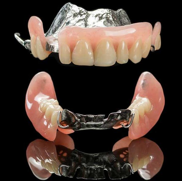
Introduction to Removable Partial Dentures
Removable Partial Dentures (RPD) serve as a critical prosthetic solution for patients who are missing some, but not all, of their natural teeth. This overview provides the foundational concepts necessary for understanding the design and application of these appliances.
Academic Presentation Details
- Presenter: Dr. Marrwa Ibrahim
- Affiliation: Lecturer, UWA Dental School
Introduction to Removable Partial Dentures2
This section provides an introductory overview of Removable Partial Dentures (RPD), focusing on their role in dental restoration and the fundamental concepts governing their use.
Definition and Key Terms34
Fundamental Terminology
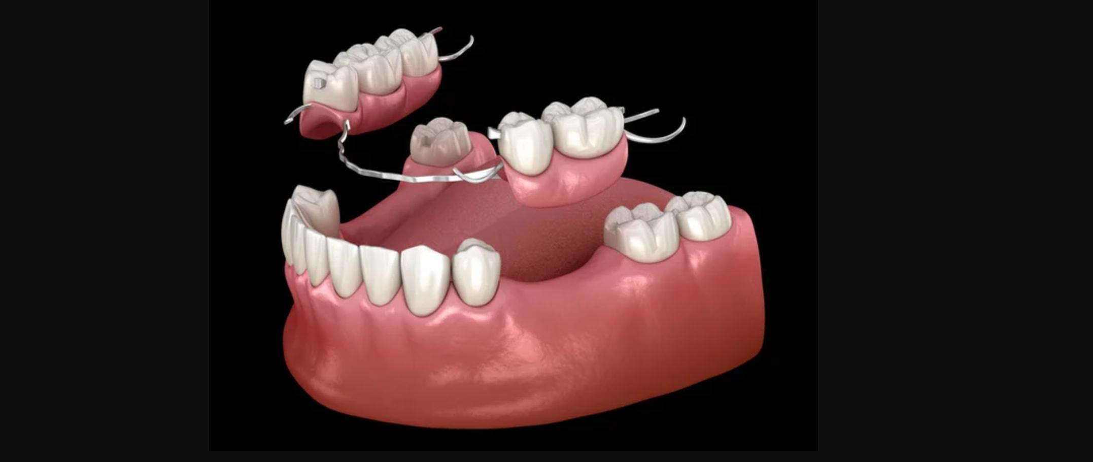
- Removable Partial Denture (RPD): A removable prosthesis replacing one or more missing teeth and associated tissues.
- Partially Edentulous Arch: An arch with remaining natural teeth and one or more edentulous areas.
- Abutment Tooth: A tooth that provides support, retention, and stability for an RPD.
Functional and Structural Components
- Support vs. Stability vs. Retention: These represent different mechanical functions that guide RPD design decisions.
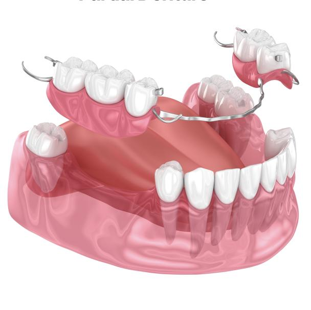
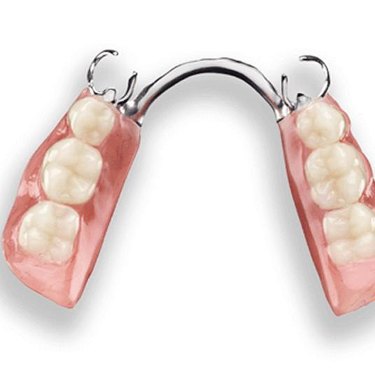
- RPD Framework: The metal or polymer “skeleton” that supports the denture base and the clasp assemblies.
Key Design and Biomechanics Terms567
Placement and Guidance
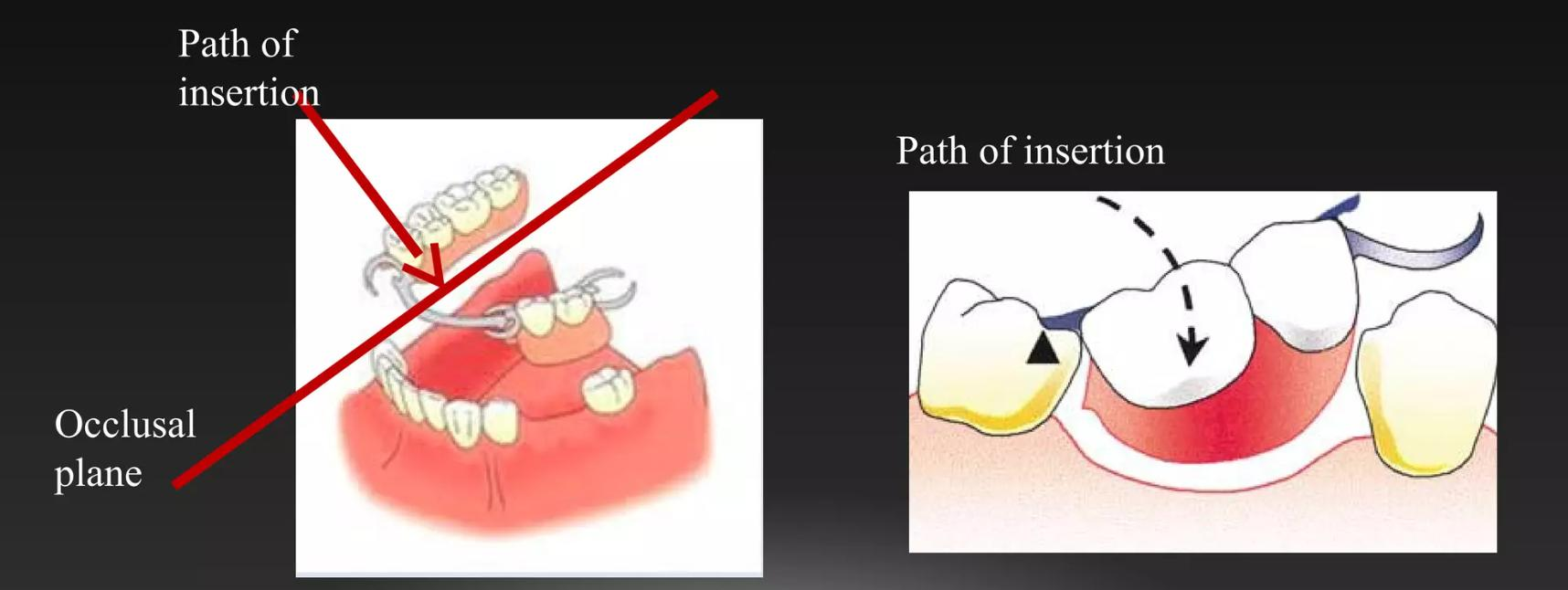
- Path of Insertion: The specific direction in which an RPD is placed onto and removed from the abutment teeth.
- Guide Plane: A prepared axial surface on an abutment tooth designed to help guide the placement of the prosthesis and improve its stability.
Tooth Contours and Retention
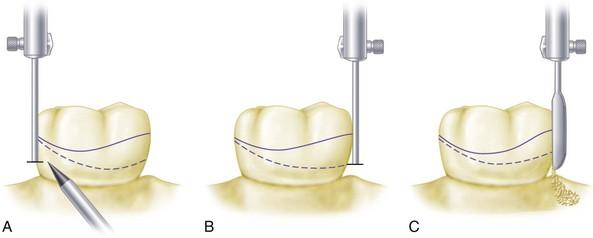
- Survey Line (Height of Contour): The line marking the greatest bulge on a tooth surface relative to the chosen path of insertion.
- Retentive Undercut: The area of a tooth located below the height of contour that is engaged by a retentive clasp tip to provide resistance to dislodgement.
Rotational Dynamics
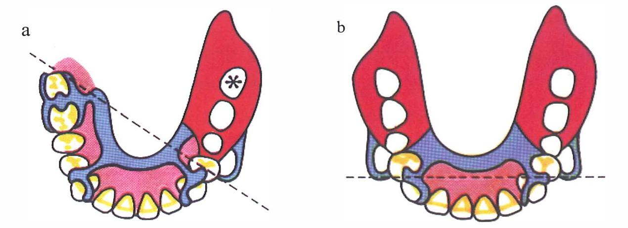
- Fulcrum Line: An imaginary axis around which a distal-extension RPD may rotate during functional loading.
Clinical Indications of Removable Partial Dentures
Clinical Scenarios for RPD Use
Primary Indications89
- Multiple missing teeth where the remaining natural teeth are suitable to serve as abutments.
- Distal extension edentulism cases where fixed restorative options are limited or not preferred by the patient.
Additional Clinical Indications
- Use as an interim or provisional prosthesis during complex treatment sequencing.
- Situations where economic, anatomical, or medical factors limit the feasibility of fixed bridges or implant therapy.
- Cases requiring cross-arch stabilization and the restoration of occlusal support.

Practical Considerations and Limitations10
Patient and Environmental Factors
- Patient Factors: Success depends on patient motivation, ability to maintain oral hygiene, personal expectations, and physical tolerance of a removable prosthesis.
- Oral Environment: Considerations include caries risk, periodontal condition, mucosal health, salivary flow, and existing occlusion.
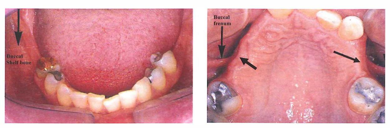
- Anatomy and Space: Evaluation of available inter-arch space, residual ridge form, frenal attachments, and the presence of tori.
Requirements for Success
RPD success is dependent on the combination of high-quality design, thorough mouth preparation, and diligent patient maintenance.
Objectives of Removable Partial Dentures1112
Core Treatment Goals
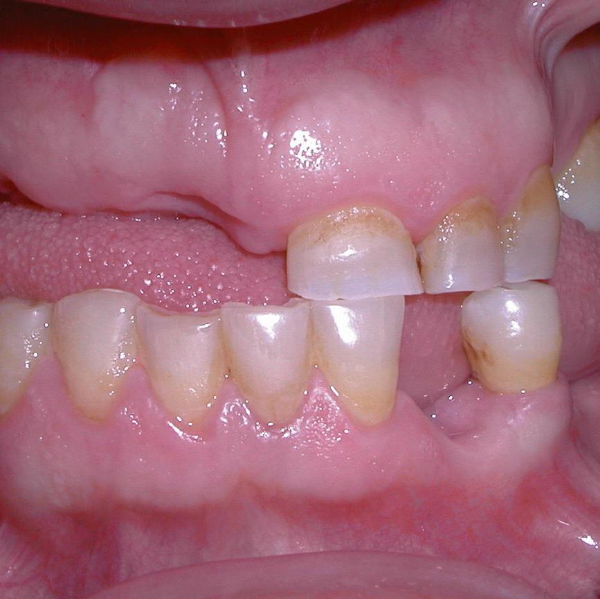
- Restore Function: Improve mastication, speech clarity, and provide necessary occlusal support.
- Restore Aesthetics: Improve tooth display, the smile line, and provide facial support where necessary.
- Preserve Oral Structures: Effectively distribute functional forces, protect remaining abutment teeth, and maintain the health of the surrounding tissues.
- Provide Comfort and Stability: Ensure secure and predictable placement and removal for the patient.
- Enable Future Treatment: Design the prosthesis so it can be modified as oral conditions change over time.
Biomechanical Principles
RPDs are biomechanically demanding; the design must be engineered to control forces exerted on both the teeth and the soft tissues.
Systematic Planning Process
Successful RPDs require a planned sequence rather than guesswork:
- Classify the arch
- Survey the diagnostic cast
- Design the framework
- Perform mouth preparation
- Take final impressions
- Fabricate the framework
- Delivery to the patient
Design choices directly determine patient comfort, the biological response of the tissues, and the longevity of the abutment teeth.

Hazards of Improperly Designed Partial Dentures13
An improperly designed and constructed partial denture may adversely affect oral tissues in the following ways:
1. Dental Decay
Stagnation of food around component parts of the partial denture that are in contact with tooth surfaces (especially those not readily cleaned) can lead to rapid tooth decay.
2. Pathologic Tissue Changes
Inducing stresses on abutment teeth and tissues that exceed physiologic limits can cause destructive changes:
- Periodontal Damage: Excessive stresses on abutments can cause periodontal membrane destruction, pocket formation, increased mobility, and eventual tooth loss.
- Soft Tissue Injury: Inflammation, ulceration, and gingival recession may occur due to excessive stress or undue tissue coverage. Inadequate support (lack of proper rests/stoppers) can cause the restoration to displace toward the tissues, resulting in “gum stripping.”
- Bone Resorption: Improper stress distribution can lead to bone resorption and the loss of the bony foundation required to support the prosthesis.
3. Joint Dysfunction
Improper occlusion or the presence of premature contacts in the RPD design may lead to Temporomandibular Joint (T.M.J.) disorders.
Classification of Partially Edentulous Arches14
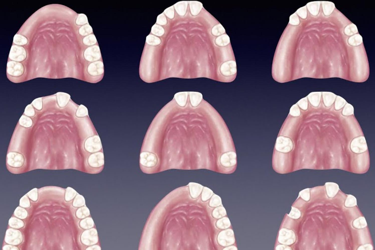
The systematic categorization of partially edentulous arches is essential for effective treatment planning and communication in Removable Partial Denture (RPD) therapy.
Purpose of Classification15
Classifying partially edentulous arches serves several critical functions in clinical practice:
- Professional Communication: Provides a common language for clinicians and laboratory technicians to discuss design planning.
- Biomechanical Prediction: Helps predict the support pattern of the prosthesis, distinguishing between tooth-supported and tooth-tissue supported designs.
- Design Guidance: Informs specific design features, including:
- Denture base extension requirements.
- The need for indirect retention.
- Appropriate clasp selection.
The most widely adopted system in dental practice is the Kennedy classification.
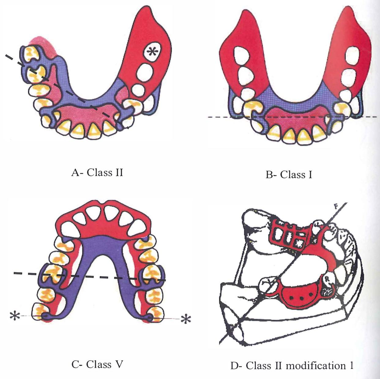
Kennedy Classification Overview1617
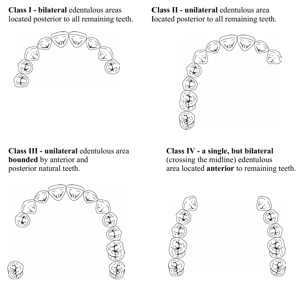
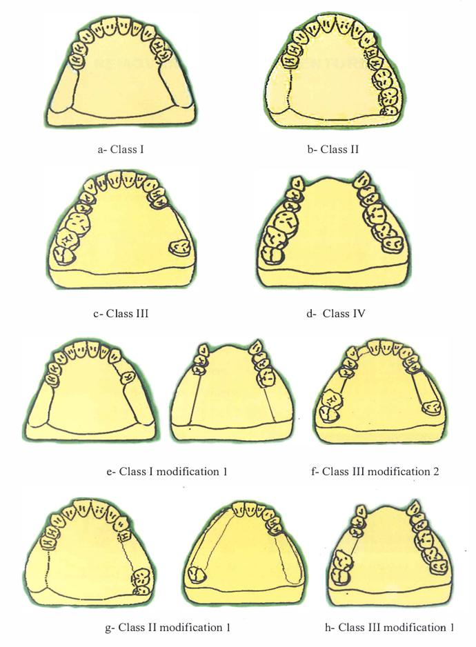
The Kennedy system categorizes arches into four primary classes based on the location of edentulous areas:
- Class I: Bilateral posterior edentulous areas located posterior to the remaining natural teeth (distal extensions).
- Class II: A unilateral posterior edentulous area located posterior to the remaining natural teeth (distal extension).
- Class III: A unilateral edentulous area with natural teeth remaining both anterior and posterior to it (tooth-supported).
- Class IV: A single, but bilateral (crossing the midline), edentulous area located anterior to the remaining natural teeth.
Modification Spaces
Additional edentulous areas that exist beyond the primary classification are referred to as modification spaces. These apply to Classes I, II, and III, but not to Class IV.
The Kennedy classification system is defined by the following categories:
- Class I: Bilateral posterior edentulous areas (distal extensions).
- Class II: Unilateral posterior edentulous area (distal extension).
- Class III: Unilateral edentulous area with teeth remaining both anterior and posterior.
- Class IV: Single anterior edentulous area crossing the midline.
Modification Spaces
Modification spaces are additional edentulous areas beyond the primary class. Note that Class IV arches do not have modification spaces; if an additional space were present, the classification would change based on the more posterior area.
Applegate Rules and Modification Spaces18
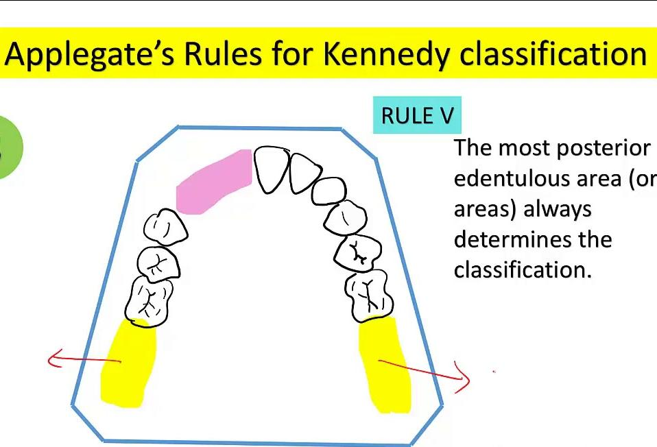
To ensure consistency in applying the Kennedy system, Applegate’s rules must be followed:
- Timing of Classification: Classification should be determined only after any necessary extractions have been completed to reflect the final arch form.
- Primary Classification: The most posterior edentulous area (or areas) always determines the classification.
- Modification Spaces:
- Additional edentulous areas are designated as modification spaces.
- These are identified by number only (e.g., modification 1, modification 2).
- The physical extent or length of the modification space is not considered.
- Class IV Exception: There are no modification spaces for Class IV arches.
- Third Molar Considerations: If a third molar is missing and is not intended to be replaced, it is excluded from the classification.
- Second Molar Considerations: If a second molar is missing and is not to be replaced, it may not influence the classification, depending on clinical judgment.
Classification Practice19
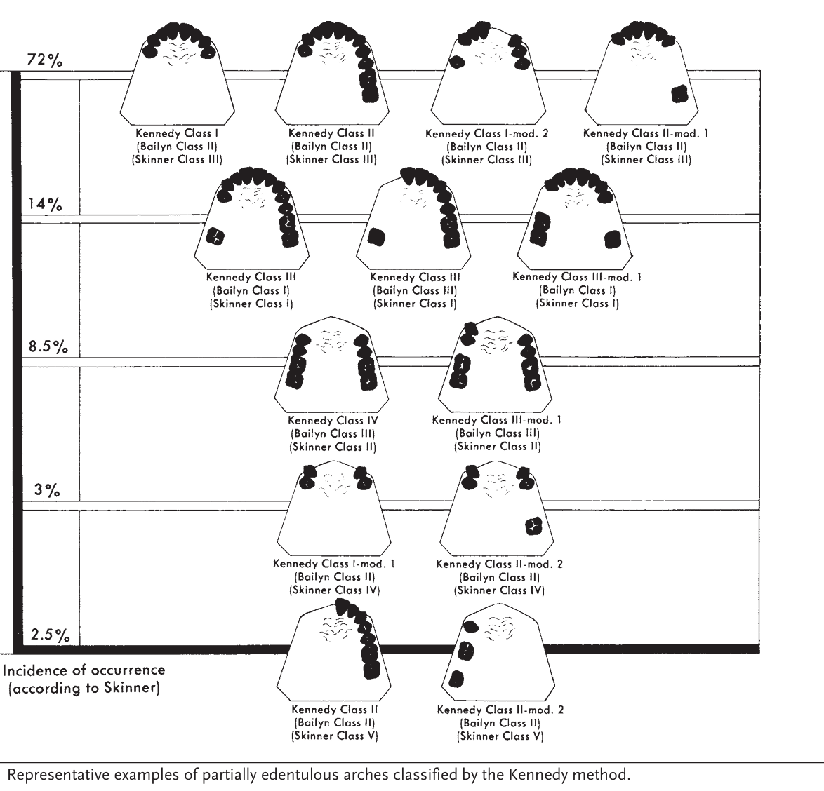
The following table illustrates the incidence of occurrence (according to Skinner) and provides representative examples of partially edentulous arches classified by the Kennedy method, alongside comparisons to Bailyn and Skinner systems.
Incidence and Comparative Classifications
-
72% Occurrence
- Kennedy Class I (Bailyn Class II, Skinner Class III)
- Kennedy Class II (Bailyn Class II, Skinner Class III)
- Kennedy Class I, modification 2 (Bailyn Class II, Skinner Class III)
- Kennedy Class II, modification 1 (Bailyn Class II, Skinner Class III)
-
14% Occurrence
- Kennedy Class III (Bailyn Class I, Skinner Class I)
- Kennedy Class III (Bailyn Class III, Skinner Class I)
- Kennedy Class III, modification 1 (Bailyn Class I, Skinner Class I)
-
8.5% Occurrence
- Kennedy Class IV (Bailyn Class III, Skinner Class II)
- Kennedy Class III, modification 1 (Bailyn Class III, Skinner Class II)
-
3% Occurrence
- Kennedy Class I, modification 1 (Bailyn Class II, Skinner Class IV)
- Kennedy Class II, modification 2 (Bailyn Class II, Skinner Class IV)
-
2.5% Occurrence
- Kennedy Class II (Bailyn Class II, Skinner Class V)
- Kennedy Class II, modification 2 (Bailyn Class II, Skinner Class V)
Components of Partial Dentures20
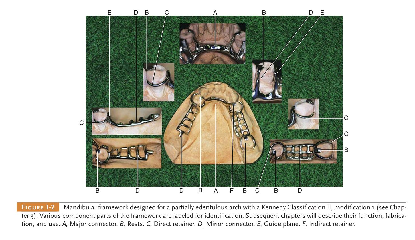
The following components are identified in a typical mandibular framework (Kennedy Classification II, modification 1):
- A: Major connector
- B: Rests
- C: Direct retainer
- D: Minor connector
- E: Guide plane
- F: Indirect retainer
These parts work together to provide stability, support, and retention for the prosthesis.
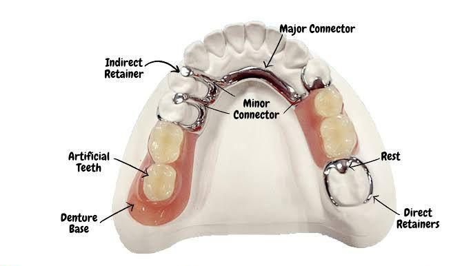
Overview of RPD Components21
An RPD consists of several integrated parts, each serving a specific mechanical purpose:
- Framework: Provides rigidity and connects components across the arch.
- Denture base: Supports replacement teeth and transmits forces to the underlying tissues.
- Rests/rest seats: Provide vertical support and prevent tissue-ward movement.
- Connectors:
- Major: Provides cross-arch connection.
- Minor: Links the major connector to saddles or retainers.
- Retainers:
- Direct: Clasp assemblies that resist displacement.
- Indirect: Control rotation of the denture.
Functions of RPD Components22
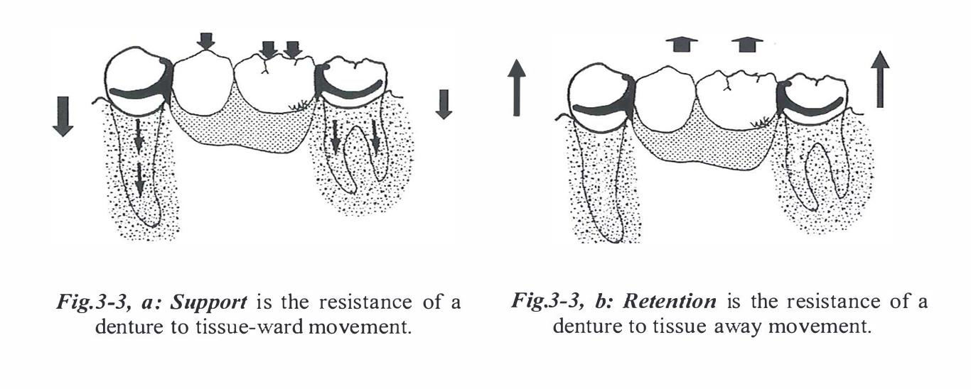
Core Mechanical Functions
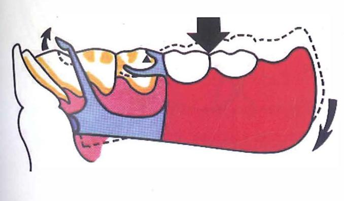
- Support: The resistance of a denture to tissue-ward movement.
- Retention: The resistance of a denture to vertical displacement force (moving away from its tissue foundation).
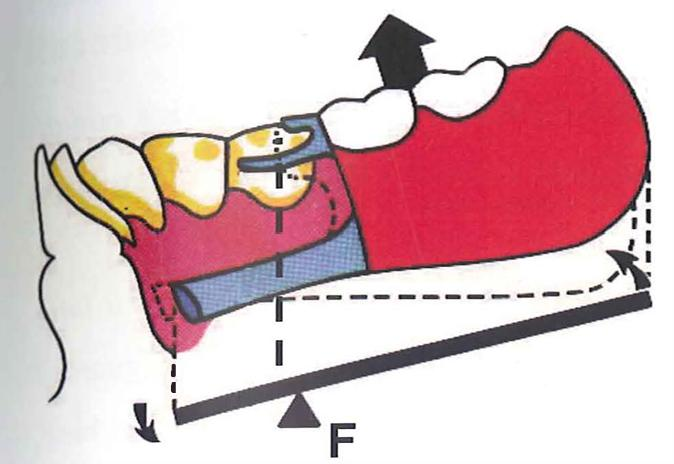
- Indirect retention: The resistance of denture rotation away from the tissues about an axis.
- Bracing: The resistance of a denture to lateral forces.
- Reciprocation: The resistance of lateral forces on the abutment during insertion and removal of the RPD.
- Note: Reciprocation is required during occlusal displacement, while bracing occurs when the denture is fully seated.
- Stability: The resistance of a denture to tipping movement.
- Tipping movement: Vertical rotation around a line parallel to the ridge crest (twisting of the denture base).
Denture Bases23
Functions and Design Goals
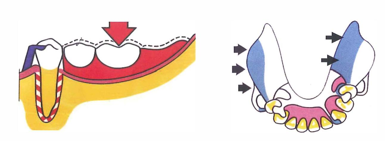
- Tooth Replacement: Replaces missing teeth and associated tissues while providing support for artificial teeth.
- Load Transmission: Transmits functional loads to teeth and mucosa; distal extensions rely more heavily on mucosal support.
- Coverage: Maximize coverage within functional limits to improve support and stability.
- Stability: Achieved via proper extension and intimate tissue adaptation.
- Maintenance: Design should allow for future relines, rebases, or repairs.
- Framework Attachment: The metal framework (mesh, lattice, bead, or finish lines) provides the base for acrylic resin attachment.
- Dimensions: The base should have adequate thickness and strength without being overbulked.
- Finish Lines: Provide a defined junction between the metal framework and the acrylic resin.
- Hygiene: Design should permit easy cleaning and minimize food traps.
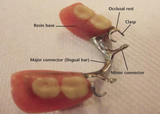
Major Connectors24
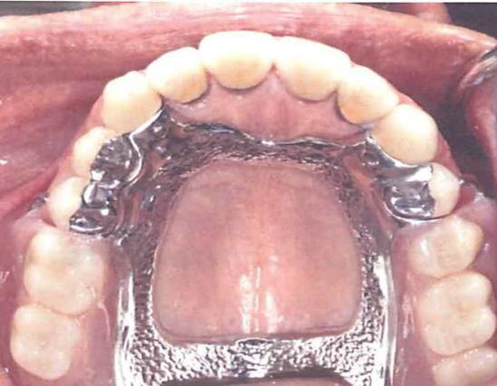
Functions and Requirements
- Cross-Arch Stabilization: Unites RPD components across the arch and distributes forces.
- Rigidity: Must be rigid to distribute forces effectively and prevent flexure.
- Tissue Health: Should avoid impinging on gingival margins and allow for hygiene access.
- Patient Comfort: Borders should be shaped for comfort and to minimize food entrapment.
- Anatomical Considerations: Design is influenced by palatal/lingual anatomy and the presence of tori.
Maxillary Major Connectors25
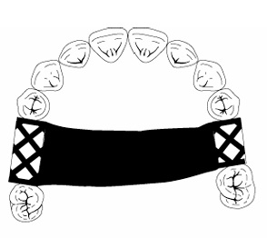
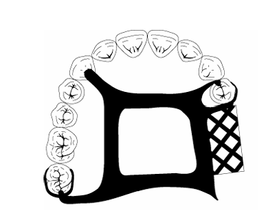
Common Maxillary Designs
- Types: Palatal strap/bar, anteroposterior (A-P) strap, palatal plate, and U-shaped connector.
- Selection Criteria: Based on support needs, palatal shape, tooth distribution, and the presence of tori.
- Rigidity: Aim for maximum rigidity with minimal tissue coverage compatible with support requirements.
- Gingival Clearance: Borders should generally be kept away from gingival margins where possible.
- Relief: Relief may be required over the midline suture or torus areas.
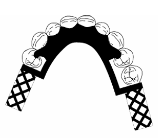
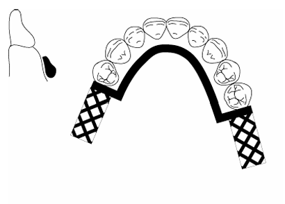
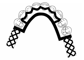
Mandibular Major Connectors26
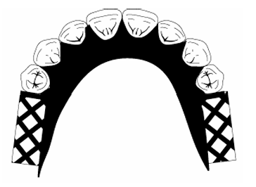
Common Mandibular Designs
- Lingual Bar: Requires adequate functional depth of the floor of the mouth.
- Lingual Plate: Indicated when floor depth is limited or when additional stabilization is required.
- Gingival Health: Must avoid gingival impingement and allow for cleaning of the gingival margins.
- Anatomical Respect: Connector borders must respect tongue movement and frena.
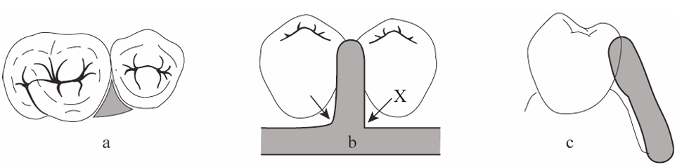
Minor Connectors27
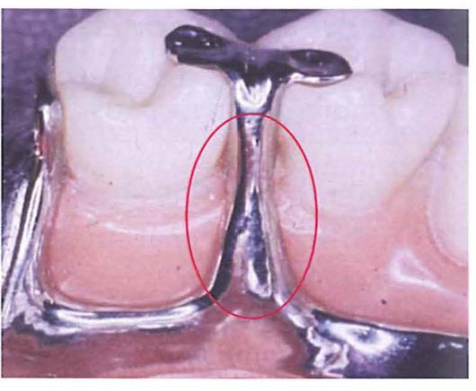
Primary Functions
- Integration: Joins the major connector to other components such as rests, clasp assemblies, and denture bases.
- Force Distribution: Transmits forces between the teeth, the base, and the major connector.
- Bracing: Provides bracing and stabilization through contact with guiding planes (proximal plates).
- Acrylic Support: Defines finish lines and supports acrylic attachments.
- Structural Integrity: Supports the principle of rigid cross-arch design.
Design Principles of Minor Connectors28
Structural Requirements
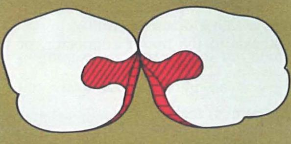
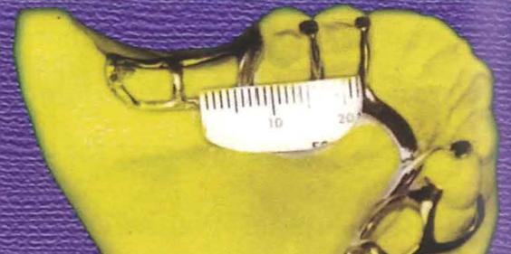
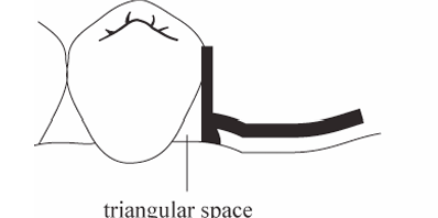
- Rigidity: Must be rigid and properly contoured to avoid soft tissue impingement.
- Guiding Planes: Proximal plates should maintain appropriate contact with prepared guiding planes.
- Tissue Protection: Avoid unnecessary coverage of gingival tissues.
- Embrasure Clearance: Maintain adequate clearance to avoid food traps.
- Finish Lines: Provide well-defined junctions for the acrylic resin.
Clasp Assembly
Clasp assemblies are essential for providing retention and stability. Retentive tips should be placed to avoid areas prone to food impaction or soft tissue interference.
Components of the Clasp Assembly
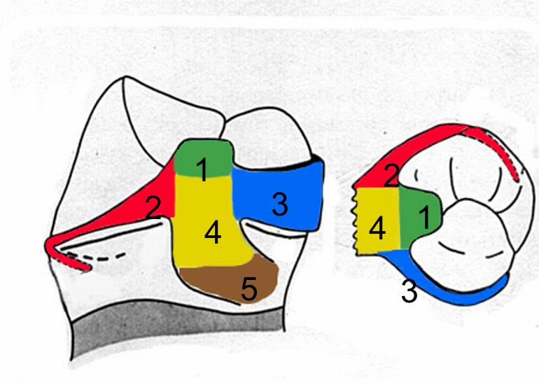
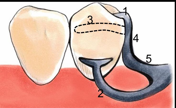
Components of Clasp Assembly29
- Rest
- Retentive arm
- Reciprocating arm
- Clasp body (proximal plate)
- Minor connector
Function of Clasp Assembly30
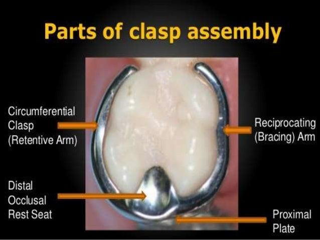
Component Functions
- Rest: Provides support and a positive seat.
- Retentive clasp arm: Engages an undercut to resist dislodgement.
- Reciprocal/bracing element: Counteracts lateral forces during insertion and removal.
- Minor connector: Connects the clasp assembly to the major connector.
- Proximal plate: Contributes to guidance and stabilization when utilized in the design.
Rests and Rest Seats31
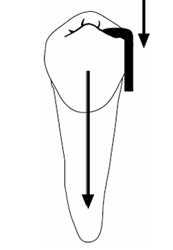
Primary Functions
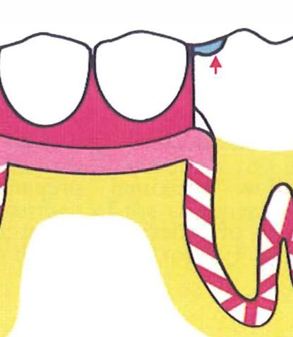
- Vertical Support: Prevents tissue-ward movement of the RPD.
- Positional Maintenance: Maintains the occlusal relationship and the position of the framework.
- Force Direction: Directs forces along the long axis of abutment teeth.
- Stability: Contributes to overall stability and assists in indirect retention, particularly in distal extension cases.
- Positive Seating: Ensures the framework does not slide or shift.
Occlusal Rest Seats32
Design Requirements
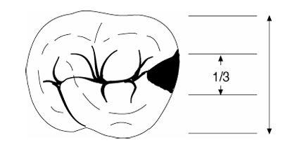
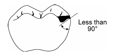
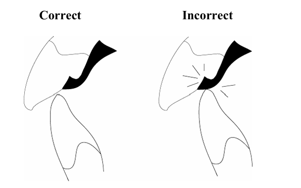
- Positive Seat: The angle at the floor of the rest seat should be less than 90° to resist slipping.
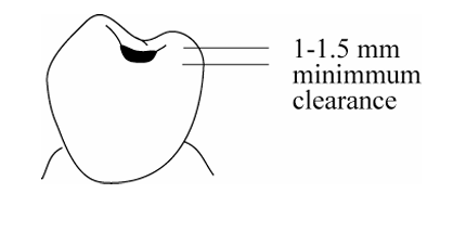
- Metal Thickness: Ensure adequate thickness of metal at the rest for structural strength.
- Stress Reduction: Internal line angles should be rounded to reduce stress concentration.
- Marginal Ridge: Maintain the integrity of the marginal ridge while providing necessary clearance.
- Periodontal Health: Avoid creating food traps or periodontal irritants.
Cingulum and Incisal Rests33
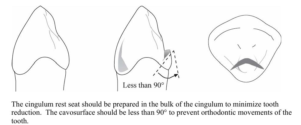
Cingulum Rests
- Common on canines and premolars.
- Aim for a positive seat while preserving enamel.
- Rest seats should be prepared in conjunction with guiding plane preparation.
Incisal Rests
- Used when a cingulum rest is not feasible.
- Generally less aesthetic than cingulum rests.
Common Errors and Alternatives
- Preparation Errors: Seats that are too shallow (weak), too deep (pulpal risk), or have wrong angulation (slippage).
- Bonded Rests: Composite bonded rests may be used when natural anatomy is inadequate.
Indirect Retention
Principles of Indirect Retention
Indirect Retention via Rests34
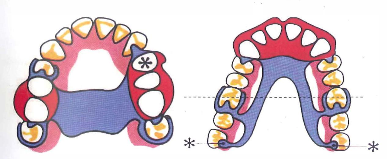
- Function: Indirect retainers resist the rotation of a distal extension base away from the tissues.
- Placement: Typically implemented via a rest placed anterior to the fulcrum line.
- Effectiveness: Increases with the distance from the fulcrum line and the quality of prepared guiding planes.
- Limitations: Complements, but does not replace, proper support and base extension.
- Planning: Must be planned during the initial design stage rather than as an afterthought.
Direct Retainers35
Overview of Direct Retainers
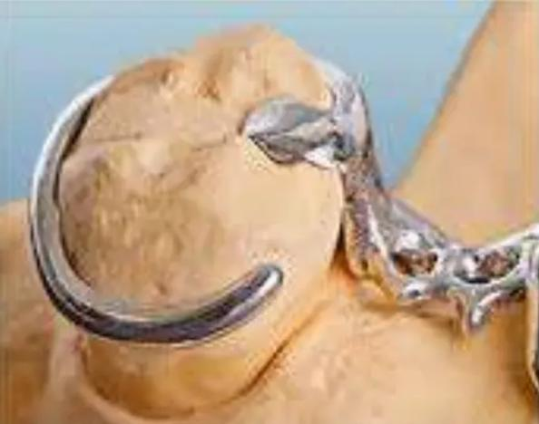
A direct retainer engages an abutment tooth to resist displacement of the RPD away from the basal seat tissues.
- Standard Components: Retentive arm, reciprocal (bracing) element, rest, and minor connector.
- Mechanical Categories:
- Intracoronal: Precision attachments.
- Extracoronal: Clasps.
- Clasp Approaches:
- Suprabulge: Approaches from above the height of contour.
- Infrabulge: Approaches from below the height of contour.
Abutment Approach
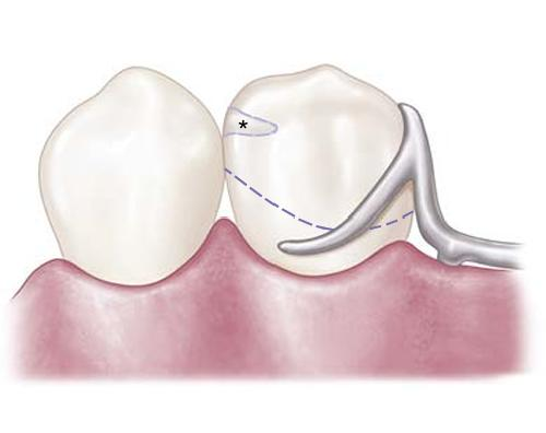
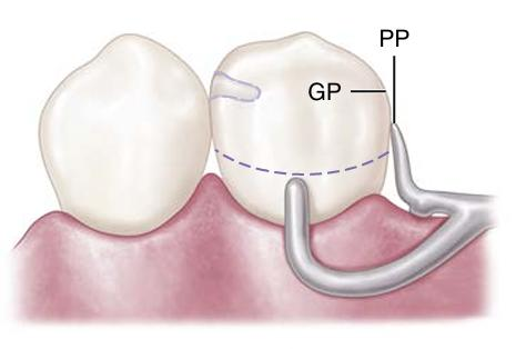
Supra-Bulge Approach36
Supra-bulge Approach
- The retentive arm approaches the undercut region from the occlusal direction.
- Maintains continuous contact with the crown.
- Direction: From occlusal to gingival.
- The arm must be pulled over the height of contour.
Infra-bulge Approach
- The retentive arm approaches the undercut region from the apical direction.
- Features short contact of the retentive arm with the crown.
- Direction: From gingival to occlusal.
- The arm must be pushed over the height of contour.
Classification of Direct Retainers
Direct retainers are classified based on their location relative to the edentulous area:
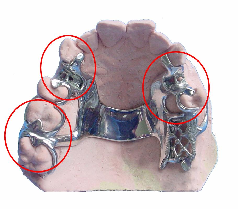
By Retention Location37
- Direct Retainer: Located adjacent to the edentulous area.
- Indirect Retainer: Located away from the edentulous area.
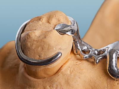
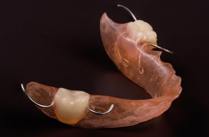
By Fabrication Method38
Direct retainers are classified by their manufacturing process:
- Casting: Custom-cast metal components.
- Wrought Wire: Pre-formed or adapted wire components.
Biomechanical Requirements39
Core Biomechanical Needs
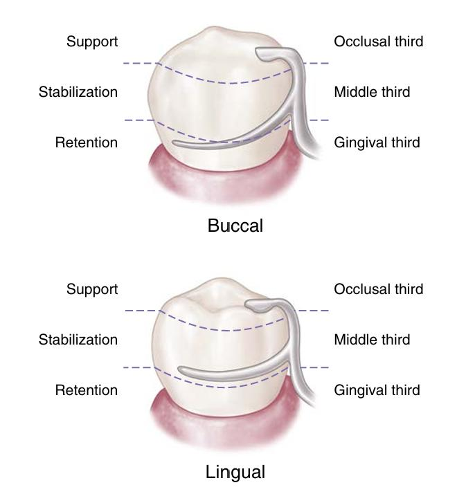
- Retention: Resists occlusal displacement; provided by the terminal third of the retentive arm.
- Support: Primarily provided by the rest; distributes loads through abutment teeth to protect soft tissues and the periodontium.
- Stabilization: A bracing effect that resists horizontal forces evenly across all abutment teeth.
Functional Requirements40
Essential Requirements
- Support: Resistance to gingival displacement (via rests).
- Reciprocity: Counters forces as the retentive arm flexes over the height of contour.
- Stability: Resistance to lateral displacement (via reciprocal arms and minor connectors).
- Retention: Engagement of a planned undercut by the retentive arm.
- Encirclement: Must encompass >180° of the tooth to prevent the prosthesis from moving away from the abutment.
- Passivity: The retainer should exert no force on the tooth when fully seated.
- Clinical Application: Select retainers to fit existing tooth forms; use tooth preparation only when necessary.
Retention Principles41424344
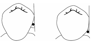
Mechanism of the Retentive Arm
- The retentive arm engages an abutment tooth undercut to resist displacement away from basal seat tissues.
- Dislodging Forces: Include gravity (especially in maxillary cases), adherent foods, and functional forces acting across a fulcrum.
Retention Fundamentals
- Undercut Engagement: Achieved by placing a flexible retentive tip into a suitable undercut.
- Depth Selection: Undercut depth must be consistent with the clasp material and design.
- Passivity: Clasps must be passive when seated, providing retention only during attempted dislodgement.
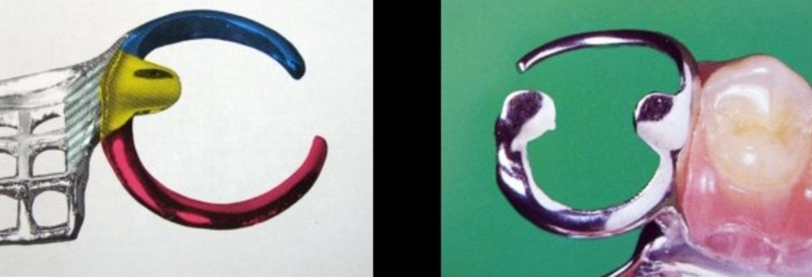
- Encirclement: The assembly must surround >180° of the tooth to prevent slipping.
- Protection: Reciprocity and bracing are required to protect the abutment during insertion and removal.
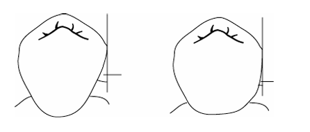
Retentive Arm Effectiveness
- Angle of Convergence: The magnitude of the angle affects retention.
- Terminal Placement: Retention depends on how far into the angle of convergence the clasp terminal is placed.
- Design Principle: Retention should be uniform in magnitude and bilaterally opposed across the arch.
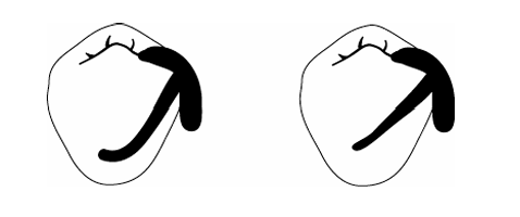
Factors Influencing Clasp Flexibility
- Length: Longer or more curved arms increase flexibility.
- Diameter: Smaller diameters increase flexibility; however, non-uniform tapering can create weak points.
- Cross-Sectional Form: Round profiles offer more flexibility than half-round profiles.
- Material: Wrought wire is generally more flexible and stronger than cast clasp arms.
Support Principles45
Support via the Rest exam
- Support is primarily provided by the rest, which distributes loading through the abutment teeth.
- This distribution protects the soft tissues and periodontium.
- Consequences of Poor Support: Without adequate support, the denture may sink into supporting tissues, causing the clasp to retreat cervically.
Stabilization Principles46
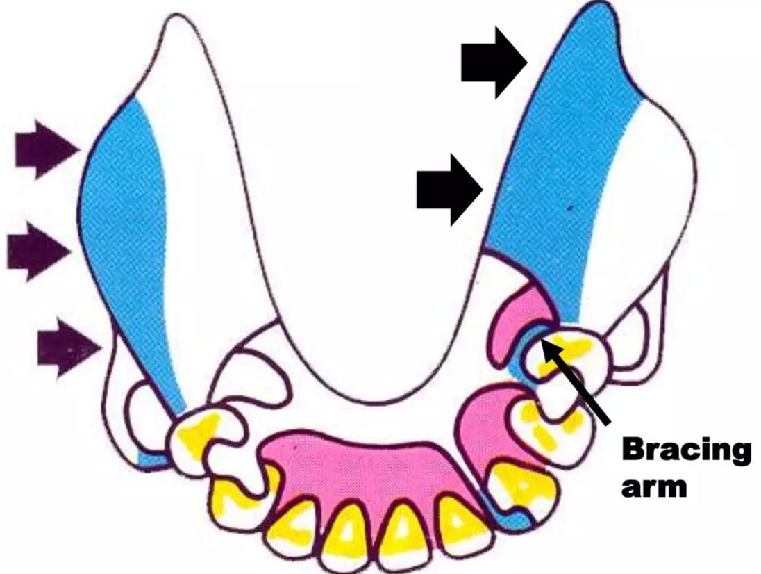
Bracing and Horizontal Resistance
- Stabilization provides a bracing effect to resist horizontal forces.
- This is most critical in distal extension cases (Kennedy Class I and II).
- Contributing Components: Achieved through the reciprocating arm, proximal plate (minor connector), and the initial third of the retentive arm. exam
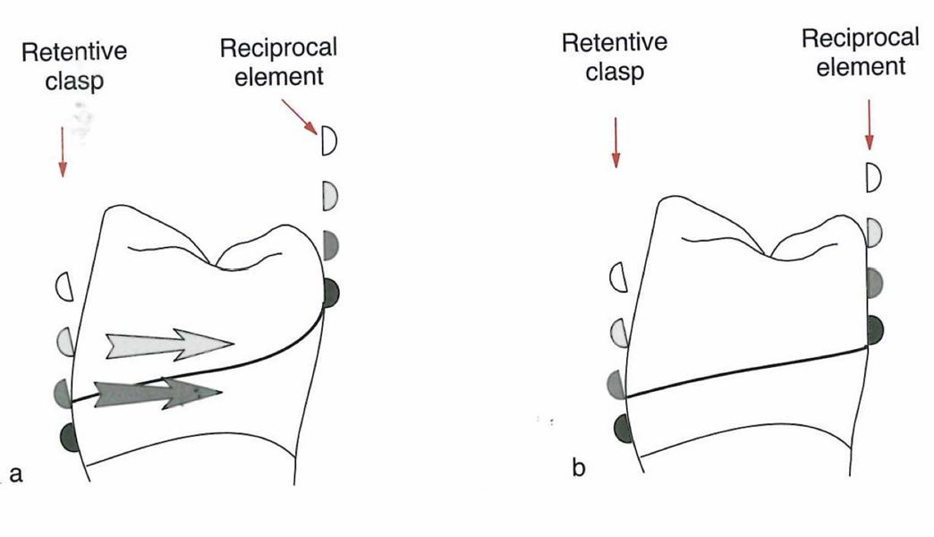
Reciprocation Principles47
Opposing Forces
- Mechanism: The insertion force of the retentive arm must be opposed by reciprocating arms or other RPD components.
- Primary Component: Mainly achieved through the reciprocating arm of the clasp assembly. exam
- Timing: Ideally, the reciprocating arm should maintain contact with the tooth at the same time the retentive arm engages.
Passivity and Encirclement484950
Passivity and Tooth Engagement
- Passivity: When fully seated, the clasp assembly must exert no active force on the tooth.
- Engagement: Components must encircle more than 180° of the tooth circumference to prevent the abutment from moving out of the assembly.
Indirect Retainer Application
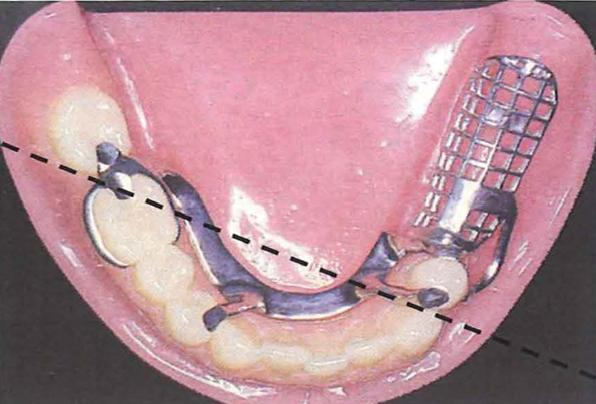
- Definition: Components used to reduce the tendency of the denture to rotate in an occlusal direction about the fulcrum axis.
- Indications: Most important in distal extension cases (Kennedy Class I and II).
- Placement: Positioned anterior to the fulcrum line to resist rotational displacement.
Effectiveness of Indirect Retention
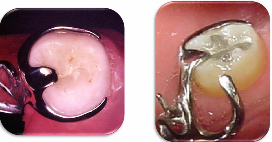
- Preparation: Requires a well-prepared rest seat and guiding plane.
- Location: Select sites with strong periodontal support and favorable anatomy.
- Long-Span Cases: Consider multiple indirect retainers for long-span distal extensions.
- Framework Rigidity: Indirect retention is also supported by the overall rigidity of the denture framework.
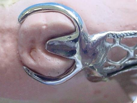
Types of Direct Retainers
Circumferential Clasps5152
Simple Circumferential Design
- The most versatile and simple clasp.
- Features one retentive arm opposed by a reciprocal arm originating from the rest.
- Use: Molars and premolars.
- Limitation: Not ideal if the abutment is tilted toward the edentulous space.
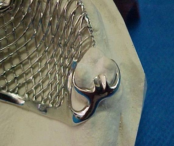
Reverse Circumferential Design
- The rest and body are located opposite the edentulous area; arms run toward the space.
- Requires a proximal plate.
- Indication: Abutment tilted toward the edentulous space.
- Limitation: Difficult to use with short clinical crowns.
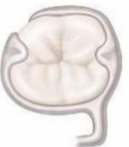
Ring Clasp Design
- Features mesial and distal rests.
- Encircles nearly the entire tooth.
- Use: Molars tipped in a mesiolingual direction.
- Limitation: Not recommended for free-end saddles.
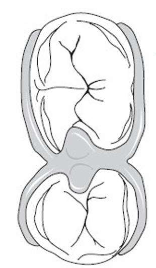
Embrasure Clasp Design
- Consists of two simple circumferential clasps joined at the bodies.
- Requires sufficient occlusal clearance.
- Function: Provides indirect retention.
- Limitation: Requires extensive tooth preparation.
Bar Clasps5354
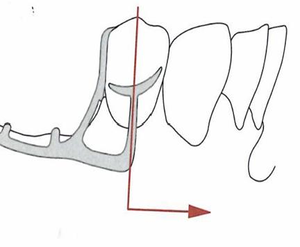
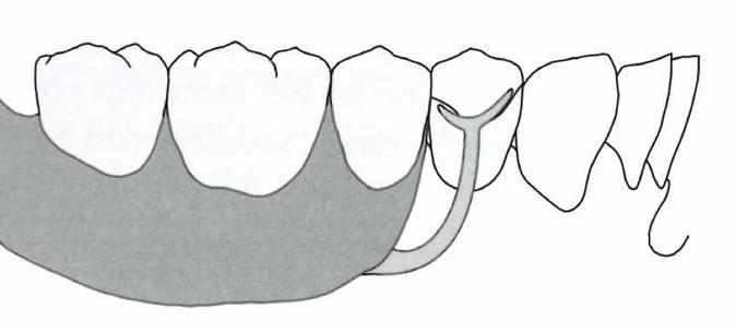
T-Clasp Design
- The approach arm originates from components in the edentulous area.
- The retentive arm crosses the gingival margin at 90°.
- Indication: Intercalated or free-end edentulous areas.
- Limitations: Interference with frenulum; severe soft tissue undercuts.
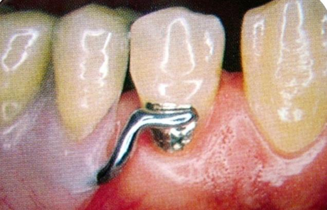
Modified T-Clasp Design
- Features only one horizontal projection.
- Designed to avoid significant soft tissue undercuts.
- Indication: Intercalated or free-end edentulous areas.
- Limitations:
- Frenulum interference.
- Severe soft tissue undercuts (risk of food entrapment and irritation).
- Height of contour located near the occlusal surface.
I-Clasp Design
- Crosses the gingival margin perpendicularly.
- Should be placed mesially to the midfacial prominence of the abutment.
- Indication: Intercalated or free-end edentulous areas.
- Limitations: Frenulum interference, severe soft tissue undercuts, and high height of contour.
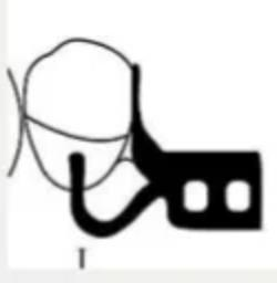
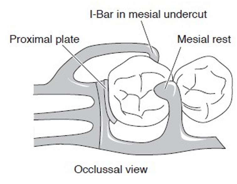
RPI Clasp Design
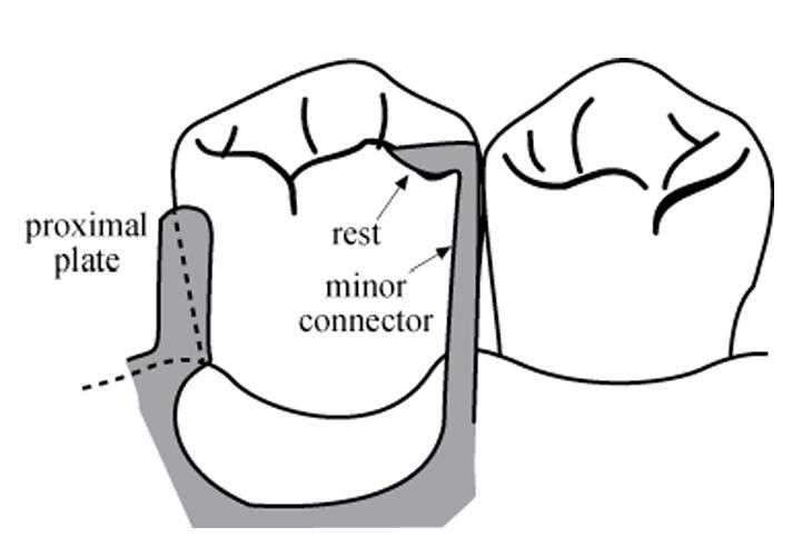
- Components: Rest (R), Proximal plate (P), and I-bar (I).
- Placement: The I-bar is located in the mesio-buccal undercut.
- Preparation: Requires guiding planes prepared from gingival to occlusal.
- Indication: Kennedy Class I and II cases.
Surveying, Path of Insertion, and Guiding Planes55
The following sections detail the principles of surveying, establishing the path of insertion, and the preparation of guiding planes for removable partial dentures (RPD).
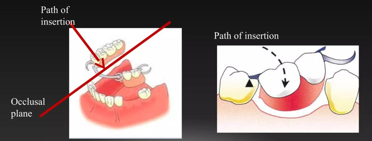
Path of Insertion56
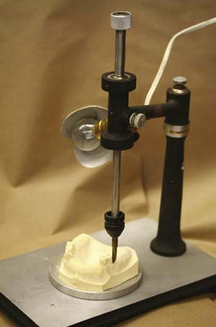
A path of insertion (or removal) is the specific direction along which a prosthesis is placed into or removed from the mouth. A removable partial denture is typically designed with a single path of insertion to provide several clinical advantages:
- Facilitates the evaluation of tooth alignment and soft tissue undercuts.
- Identifies potential interferences during the insertion and removal process.
- Ensures predictable placement and stability of the prosthesis.
Surveyors and Diagnostic Analysis5758
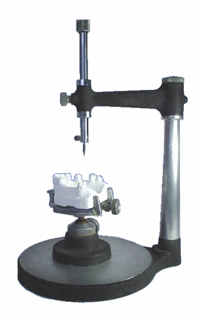
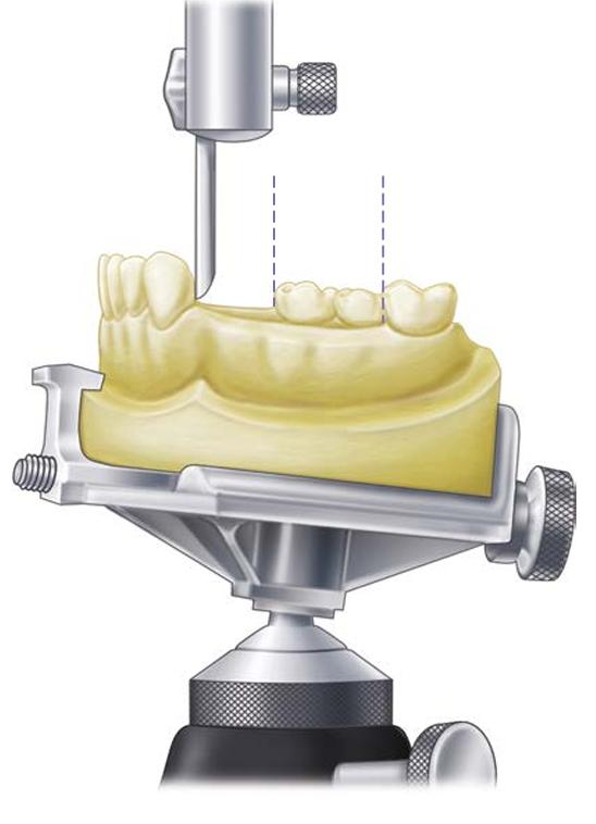
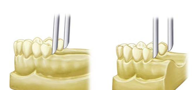
The Dental Surveyor
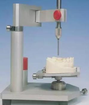
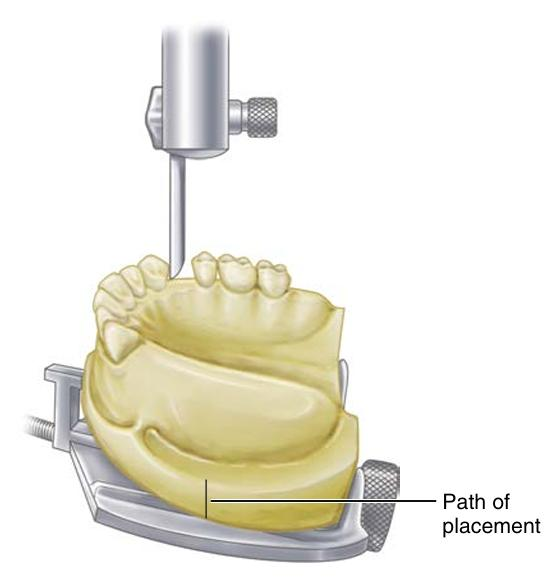
The dental surveyor is a diagnostic instrument used to select the most favorable path of insertion and aid in the preparation of guiding planes. It is an essential tool in the design of removable partial dentures. The systematic process of using this instrument is referred to as surveying.
Objectives of Diagnostic Cast Analysis
Surveying a diagnostic cast is performed to achieve the following:
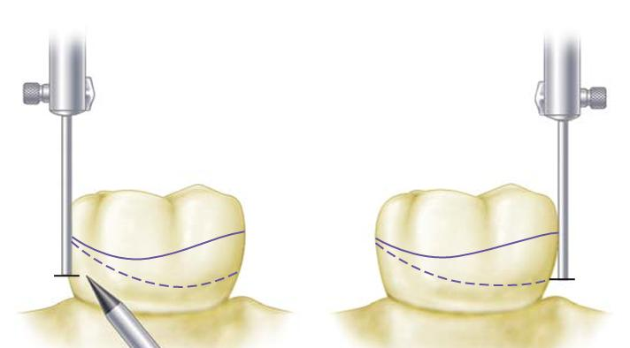
- Identify Anatomical Features: Determine the height of contour and locate usable undercuts on abutment teeth.
- Evaluate Obstructions: Assess tooth alignment and soft tissue undercuts that may interfere with the insertion or removal of the denture.
- Optimize Design: Select a path of insertion that balances retention requirements, esthetic considerations, and the need for minimal tooth modification.
- Guide Clinical Preparation: Inform decisions regarding clasp types, the location of guiding planes, and necessary mouth preparations.
- Maintain Consistency: Record the selected tilt of the cast (tripoding) to ensure the orientation can be reproduced.
Survey Lines and Undercuts59
Relationship Between Tilt and Survey Lines
- The survey line is dependent on the chosen path of insertion; changing the tilt of the cast directly alters the survey line.
- Undercuts may be located on buccal, lingual, mesial, or distal surfaces. The specific location of these undercuts influences the selection of the clasp assembly.
Clinical Considerations
- Retention vs. Esthetics: Select undercuts that provide sufficient retention while minimizing the visibility of metal components to avoid esthetic compromise.
- Soft Tissue Management: Evaluate soft tissue undercuts to prevent tissue impingement and difficulties during insertion.
- Tooth Modification: Plan for necessary enamel recontouring or the fabrication of surveyed restorations to create ideal contours.
Determining the Path of Insertion60
Selection Criteria
When determining the optimal path of insertion, the following factors must be considered:
- Interference and Stability: Minimize interferences with teeth or soft tissue while maintaining effective guidance and stability for the framework.
- Esthetics: Carefully evaluate the display of clasps, particularly in the anterior region of the mouth.
- Biomechanics: Understand that the tilt of the cast may change the availability of undercuts and the mechanical effectiveness of the clasps.
- Compatibility: Aim for a path that is compatible with the prepared guiding planes.
- Communication: Record the selected path accurately for clear communication with the dental laboratory.
Guiding Planes61
Functional Benefits
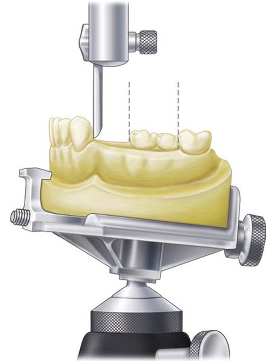
A guiding plane is a prepared axial surface of a tooth, usually 2–3 mm in height, made parallel to the path of insertion. These planes offer several benefits:
- Stability and Hygiene: Improved stability of the RPD and reduced potential for food trapping.
- Controlled Movement: Provides a controlled path for insertion and removal, making it easier for the patient to use the prosthesis.
- Component Support: Enhances the effectiveness of proximal plates and indirect retainers.
Planning and Execution
Guiding planes should be meticulously planned on diagnostic casts during the design phase and executed precisely during the mouth preparation appointment.
Guiding Plane Preparation62
Preparation Techniques
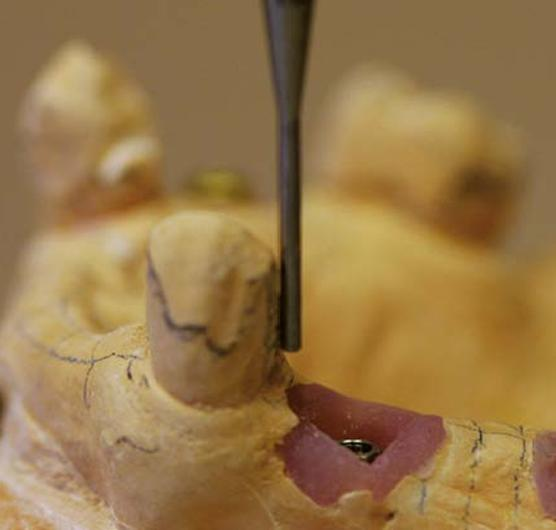
- Location: Prepare planes on proximal surfaces adjacent to edentulous areas where indicated by the design.
- Surface Quality: Maintain enamel integrity while creating smooth, parallel surfaces that are free of new undercuts.
- Conservative Reduction: Avoid over-reduction that could compromise tooth structure or lead to post-operative sensitivity.
- Verification: Check the parallelism of the prepared surfaces relative to the established path of insertion.
Common Preparation Errors
- Creating planes that are too short to be effective.
- Divergence of prepared surfaces.
- Accidental creation of new undercuts during the reduction process.
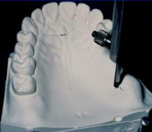
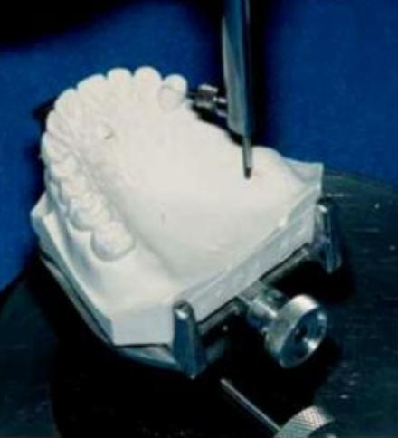
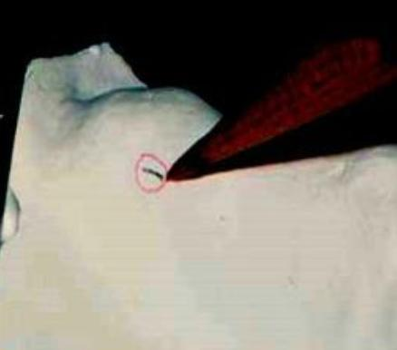
Tripoding and Cast Recording63
Purpose of Tripoding
Tripoding involves placing three widely separated marks on the cast to preserve its orientation on the surveyor. This process is critical for:
- Consistency: Allowing for consistent re-surveying after mouth preparations or design adjustments.
- Accuracy: Supporting the accurate fabrication of the framework and precise placement of clasps.
- Verification: Re-surveying the cast after altering tooth contours, preparing guiding planes, or creating rest seats to ensure the modifications match the planned design.
- Documentation: Ensuring all planned modifications are clearly documented on the laboratory prescription.
Principles of Partial Denture Design64
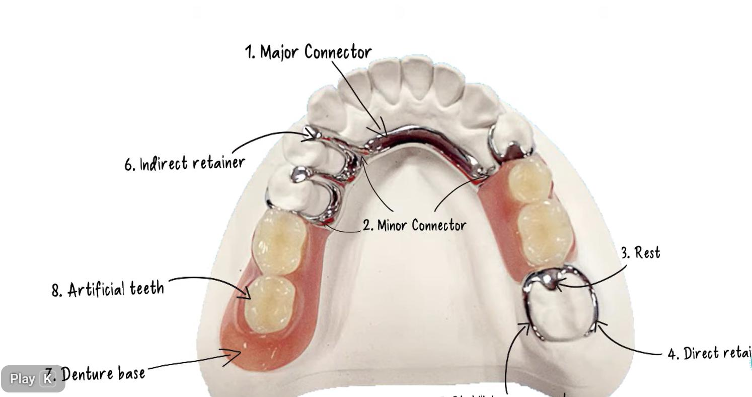
A Removable Partial Denture (RPD) is composed of several essential elements that must be integrated into a cohesive design:
- Major Connector
- Minor Connector
- Rest
- Direct retainer
- Indirect retainer
- Artificial teeth
- Denture base
Design Sequence65
The following workflow is recommended for developing a systematic RPD design:
- Diagnose and define the problem: Assess missing teeth, periodontal status, and occlusion.
- Classify the arch: Determine the Kennedy classification and identify the support type (tooth-supported vs. tooth–tissue supported).
- Survey diagnostic casts: Select an appropriate path of insertion.
- Plan mouth preparation: Determine requirements for guiding planes, rest seats, contours, and restorations.
- Component selection: Select major and minor connectors, rests, clasp assemblies, and indirect retainers.
- Plan impressions and base extension: Ensure extensions are appropriate to meet the support needs of the case.
Support and Stability Principles66
Core Support and Stability Requirements
- Maximize support: Utilize rests on suitable abutments and extend denture bases within functional limits.
- Rigidity: Major connectors must be rigid to provide effective cross-arch stabilization.
- Bracing: Incorporate reciprocal elements and guiding planes to resist horizontal forces.
- Stability: Improve stability through broad, well-adapted bases and a controlled path of insertion.
- Stress Distribution: Avoid designs that concentrate stress on a single abutment or a small area of soft tissue.
Stress Control in Distal Extension Cases67
Managing Rotational Forces
- Control Rotation: Distal extension bases rotate under load; the design must control this rotation to protect the abutments.
- Tissue Support: Use broad base extension and appropriate impression techniques to improve support from the residual ridge.
- Indirect Retention: Use indirect retainers to resist the lifting of the base away from the tissues.
- Clasp Selection: Consider clasp designs that reduce torque on abutments, depending on the specific clinical case.
- Force Distribution: Aim for even distribution of forces across teeth, tissues, and the entire arch via cross-arch stabilization.
Retention and Reciprocity Principles68
Clasp Assembly Requirements
- Retention: A flexible retentive tip must engage a planned undercut. The clasp must remain passive when the denture is fully seated.
- Reciprocity: A reciprocal element must contact the tooth as the retentive arm flexes over the height of contour to neutralize lateral forces.
- Encirclement: The clasp assembly should surround more than 180° of the tooth circumference.
- Support: Include a rest to direct forces along the long axis of the tooth and stabilize the assembly.
- Simplicity and Hygiene: Minimize tooth and tissue coverage to maintain oral health while ensuring functional requirements are met.
Hygiene, Esthetics, and Maintenance69
Design for Long-Term Success
- Periodontal Health: Minimize gingival coverage and avoid plaque-retentive contours or food traps.
- Connector Selection: Choose designs that balance necessary rigidity with patient comfort and ease of cleaning.
- Esthetics: Place clasps to minimize metal display where possible without compromising function.
- Maintenance Planning: Design with future relines, repairs, and periodic reviews in mind.
- Patient Education: Success depends on patient instruction regarding cleaning, insertion/removal, and regular recall appointments.
Kennedy Class Design Implications
Kennedy Class I cases involve bilateral distal extension base areas.
Kennedy Class I Design Implications70
Design Considerations for Bilateral Distal Extensions
- Support: Relies on tooth–tissue support, which creates a greater potential for rotation during function.
- Base Extension: Maximize denture base extension to optimize tissue support.
- Stabilization: Use rigid major connectors to provide essential cross-arch stabilization.
- Indirect Retention: Indirect retainers are usually critical to control rotational movement.
- Abutment Protection: Clasp selection should be specifically chosen to minimize torque on the primary abutments.
Kennedy Class II Design Implications71
Design Considerations for Unilateral Distal Extensions
- Loading: Unilateral distal extensions result in asymmetrical loading and rotation.
- Stabilization: Cross-arch stabilization is essential for these cases.
- Indirect Retention: Commonly required to counteract rotational forces.
- Support Factors: Denture base extension and the specific impression technique used significantly influence the quality of support.
- Abutment Safety: The design must balance the need for retention with the protection of the abutment tooth from excessive stress.
Kennedy Class III Design Implications72
Design Considerations for Bounded Edentulous Spaces
- Support: Primarily tooth-supported (bounded saddle), leading to more predictable support and stability.
- Movement: There is significantly less rotation compared with distal extension cases.
- Indirect Retention: Indirect retainers may be less critical, depending on the specific case configuration.
- Clasping and Esthetics: Clasping is often straightforward; the focus should remain on hygiene and esthetics.
- Connector Requirements: The choice of connector must remain rigid and hygienic.
Kennedy Class IV Design Implications73
Design Considerations for Anterior Midline-Crossing Extensions
- Functional Priorities: Esthetics and support are the primary considerations for this classification.
- Clinical Factors: Canine guidance, lip support, and phonetics heavily influence the positioning of the artificial teeth.
- Applegate Rules: Often, no modification spaces are allowed in a true Class IV designation.
- Esthetic Management: Clasp display should be minimized as much as possible due to the anterior location of the prosthesis.
Footnotes
-
Original PDF page 1: L11 RPD Lecture Recap pdf, p.1 ↩
-
Original PDF page 2: L11 RPD Lecture Recap pdf, p.2 ↩
-
Original PDF page 3: L11 RPD Lecture Recap pdf, p.3 ↩
-
Original PDF page 4: L11 RPD Lecture Recap pdf, p.4 ↩
-
Original PDF page 5: L11 RPD Lecture Recap pdf, p.5 ↩
-
Original PDF page 6: L11 RPD Lecture Recap pdf, p.6 ↩
-
Original PDF page 7: L11 RPD Lecture Recap pdf, p.7 ↩
-
Original PDF page 8: L11 RPD Lecture Recap pdf, p.8 ↩
-
Original PDF page 9: L11 RPD Lecture Recap pdf, p.9 ↩
-
Original PDF page 10: L11 RPD Lecture Recap pdf, p.10 ↩
-
Original PDF page 11: L11 RPD Lecture Recap pdf, p.11 ↩
-
Original PDF page 12: L11 RPD Lecture Recap pdf, p.12 ↩
-
Original PDF page 13: L11 RPD Lecture Recap pdf, p.13 ↩
-
Original PDF page 14: L11 RPD Lecture Recap pdf, p.14 ↩
-
Original PDF page 15: L11 RPD Lecture Recap pdf, p.15 ↩
-
Original PDF page 16: L11 RPD Lecture Recap pdf, p.16 ↩
-
Original PDF page 17: L11 RPD Lecture Recap pdf, p.17 ↩
-
Original PDF page 18: L11 RPD Lecture Recap pdf, p.18 ↩
-
Original PDF page 19: L11 RPD Lecture Recap pdf, p.19 ↩
-
Original PDF page 20: L11 RPD Lecture Recap pdf, p.20 ↩
-
Original PDF page 21: L11 RPD Lecture Recap pdf, p.21 ↩
-
Original PDF page 22: L11 RPD Lecture Recap pdf, p.22 ↩
-
Original PDF page 23: L11 RPD Lecture Recap pdf, p.23 ↩
-
Original PDF page 24: L11 RPD Lecture Recap pdf, p.24 ↩
-
Original PDF page 25: L11 RPD Lecture Recap pdf, p.25 ↩
-
Original PDF page 26: L11 RPD Lecture Recap pdf, p.26 ↩
-
Original PDF page 27: L11 RPD Lecture Recap pdf, p.27 ↩
-
Original PDF page 28: L11 RPD Lecture Recap pdf, p.28 ↩
-
Original PDF page 29: L11 RPD Lecture Recap pdf, p.29 ↩
-
Original PDF page 30: L11 RPD Lecture Recap pdf, p.30 ↩
-
Original PDF page 31: L11 RPD Lecture Recap pdf, p.31 ↩
-
Original PDF page 32: L11 RPD Lecture Recap pdf, p.32 ↩
-
Original PDF page 33: L11 RPD Lecture Recap pdf, p.33 ↩
-
Original PDF page 34: L11 RPD Lecture Recap pdf, p.34 ↩
-
Original PDF page 35: L11 RPD Lecture Recap pdf, p.35 ↩
-
Original PDF page 36: L11 RPD Lecture Recap pdf, p.36 ↩
-
Original PDF page 37: L11 RPD Lecture Recap pdf, p.37 ↩
-
Original PDF page 38: L11 RPD Lecture Recap pdf, p.38 ↩
-
Original PDF page 39: L11 RPD Lecture Recap pdf, p.39 ↩
-
Original PDF page 40: L11 RPD Lecture Recap pdf, p.40 ↩
-
Original PDF page 41: L11 RPD Lecture Recap pdf, p.41 ↩
-
Original PDF page 42: L11 RPD Lecture Recap pdf, p.42 ↩
-
Original PDF page 43: L11 RPD Lecture Recap pdf, p.43 ↩
-
Original PDF page 44: L11 RPD Lecture Recap pdf, p.44 ↩
-
Original PDF page 45: L11 RPD Lecture Recap pdf, p.45 ↩
-
Original PDF page 46: L11 RPD Lecture Recap pdf, p.46 ↩
-
Original PDF page 47: L11 RPD Lecture Recap pdf, p.47 ↩
-
Original PDF page 48: L11 RPD Lecture Recap pdf, p.48 ↩
-
Original PDF page 49: L11 RPD Lecture Recap pdf, p.49 ↩
-
Original PDF page 50: L11 RPD Lecture Recap pdf, p.50 ↩
-
Original PDF page 51: L11 RPD Lecture Recap pdf, p.51 ↩
-
Original PDF page 52: L11 RPD Lecture Recap pdf, p.52 ↩
-
Original PDF page 53: L11 RPD Lecture Recap pdf, p.53 ↩
-
Original PDF page 54: L11 RPD Lecture Recap pdf, p.54 ↩
-
Original PDF page 55: L11 RPD Lecture Recap pdf, p.55 ↩
-
Original PDF page 56: L11 RPD Lecture Recap pdf, p.56 ↩
-
Original PDF page 57: L11 RPD Lecture Recap pdf, p.57 ↩
-
Original PDF page 58: L11 RPD Lecture Recap pdf, p.58 ↩
-
Original PDF page 59: L11 RPD Lecture Recap pdf, p.59 ↩
-
Original PDF page 60: L11 RPD Lecture Recap pdf, p.60 ↩
-
Original PDF page 61: L11 RPD Lecture Recap pdf, p.61 ↩
-
Original PDF page 62: L11 RPD Lecture Recap pdf, p.62 ↩
-
Original PDF page 63: L11 RPD Lecture Recap pdf, p.63 ↩
-
Original PDF page 64: L11 RPD Lecture Recap pdf, p.64 ↩
-
Original PDF page 65: L11 RPD Lecture Recap pdf, p.65 ↩
-
Original PDF page 66: L11 RPD Lecture Recap pdf, p.66 ↩
-
Original PDF page 67: L11 RPD Lecture Recap pdf, p.67 ↩
-
Original PDF page 68: L11 RPD Lecture Recap pdf, p.68 ↩
-
Original PDF page 69: L11 RPD Lecture Recap pdf, p.69 ↩
-
Original PDF page 70: L11 RPD Lecture Recap pdf, p.70 ↩
-
Original PDF page 71: L11 RPD Lecture Recap pdf, p.71 ↩
-
Original PDF page 72: L11 RPD Lecture Recap pdf, p.72 ↩
-
Original PDF page 73: L11 RPD Lecture Recap pdf, p.73 ↩