Retainers12
Components of the Clasp Assembly
A clasp assembly is a fundamental component of a removable partial denture, designed to provide retention, stability, and support. It typically consists of several integrated parts working together to secure the prosthesis while protecting the abutment teeth.
- Rest: Provides vertical support and prevents the denture from moving toward the tissue.
- Retentive Arm: Engages the undercut of the abutment tooth to resist dislodgment.
- Reciprocal Arm (Stabilizing Component): Counters the forces exerted by the retentive arm during insertion and removal.
- Minor Connector: Joins the clasp assembly components to the major connector or denture base.
Components of a Removable Partial Denture (RPD) that engage abutments and resist dislodging forces.
Mechanism of Retention
The fundamental mechanism relies on elastic deformation. The retentive arm flexes slightly during insertion and removal to engage a predetermined undercut. This flexibility must remain within the elastic limit; if plastic deformation occurs, the clasp permanently loses its retentive properties.
Retentive Unit3
- Provide resistance to displacement by deformation of the retentive arm.
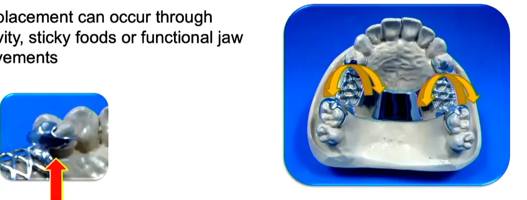
Forces Affecting Retainers4
Displacement can occur through gravity, sticky foods, or functional jaw movements.
- Masticatory movements: Normal chewing and parafunctional habits
- Gravity: Acts against upper dentures while favoring lower dentures (keeping them in position)
Classification of Retainers5
Retainers are classified into various categories based on their location, construction, and function within the prosthesis.
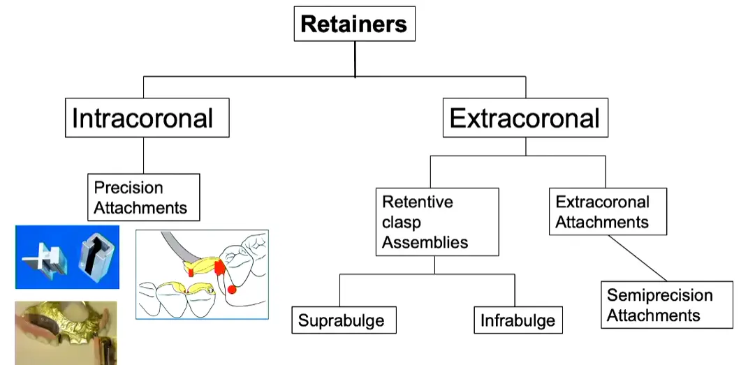
- Intracoronal Retainers
- Precision Attachments: Housed entirely within the crown contour (survey crowns)
- Characteristics: Aesthetic (hides metal), expensive, and complex laboratory fabrication
- Usage: Not typically provided in graduate clinics due to cost, but used in private practice
- Extracoronal Retainers
- Positioned outside the crown contour
- Includes traditional clasp assemblies (suprabulge, infrabulge, and semi-precision attachments)
- Represents the standard approach taught for graduate clinical cases
Direct Retainers
- Intracoronal
- Precision Attachments
- Extracoronal
- Retentive clasp Assemblies
- Extracoronal Attachments
Disadvantages of Clasp-Retained Partial Dentures (extracoronal , retentive clasp assemblies)6
- Strain on the abutment teeth often is caused by improper tooth preparation or clasp design.
- Clasps can be unaesthetic, particularly when they are placed on visible tooth surfaces.
- Static display: Metal components may be visible, creating aesthetic dissatisfaction for patients.
- Caries may develop beneath clasp components, especially if the patient fails to keep the prosthesis and the abu
Definition
Direct retainers are positioned close to the edentulous space they are retaining, as opposed to indirect retainers which are positioned far from the edentulous space (typically on the opposite side of the arch). tments clean.
Prerequisites for Treatment
Strict patient compliance is required. Patients must demonstrate adequate plaque control during the control phase before proceeding to the reconstructive phase. A holding phase between these stages allows for reassessment. If compliance is poor, treatment should not proceed. > - Plaque accumulation increases around clasp components, particularly if the patient sleeps with the prosthesis. > - Partial dentures alter plaque development, promoting subgingival microorganisms that can affect periodontal health. > - Constant force application can damage the periodontal ligament if not properly designed (must be passive when seated).
Clasp Assemblies
- Rest
- Retentive arm
- Reciprocating arm
- Clasp body: proximal plate
- Minor connector
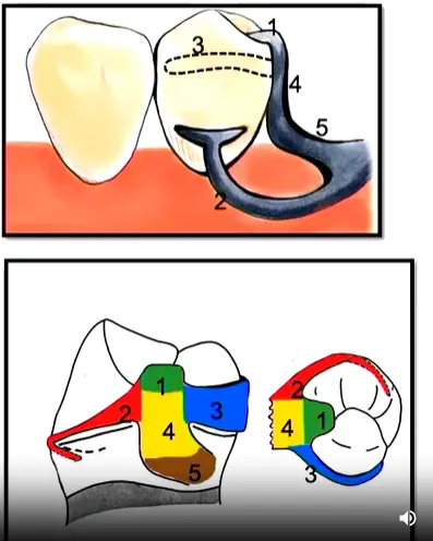
Components of Clasp Assembly7
Suprabulge and Infrabulge Clasps8
Suprabulge Clasps
- Retentive arm approaches the undercut region of the abutment from the occlusal direction.
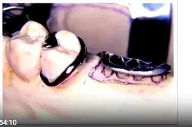
Infrabulge Clasps
- Retentive arm approaches the undercut region of the abutment from the apical direction.
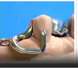
Functional Advantage
Infrabulge clasps provide a stress-releasing effect; during posterior biting, the clasp moves toward the gingiva, disengaging from the tooth to reduce functional load.
Classification of Clasp Assemblies9
According to Retention
- Direct retainer: Adjacent to the edentulous area.
- Indirect retainer: Away from the edentulous area, provides indirect retention.
According to Construction10
- Adapted, wrought wire
- Cast
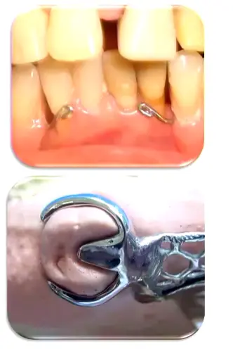
Requirements for the Retentive Unit11
1. Support
- Mainly provided by the rest.
- Distributes loading through the abutment teeth.
- Protects the soft tissues and periodontium.
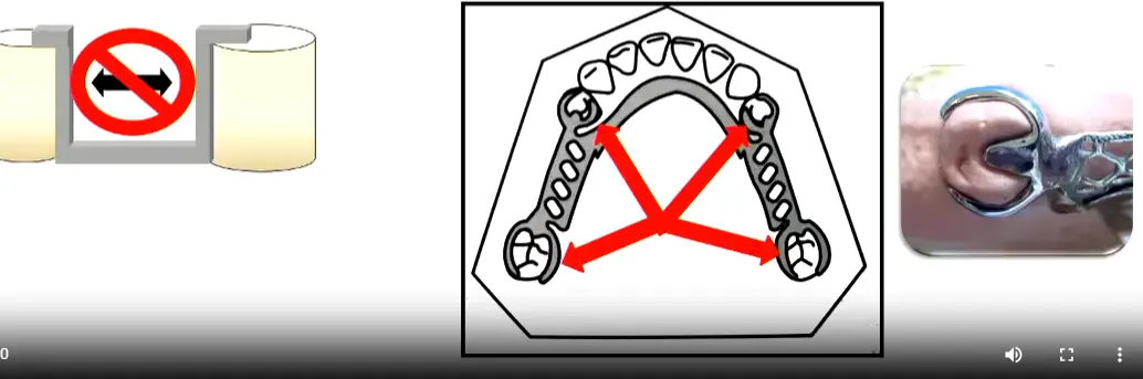
2. Stabilization12
Bracing effect resists horizontal forces evenly through all abutment teeth. Components involved include:
- Reciprocating arm
- this is rigid
- Proximal plate (minor connector)
- Initial third of the retentive arm
3. Retention13
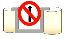
- Resists occlusal displacement.
- Provided by the terminal third of the retentive arm.
- Retention should be distributed throughout the arch.
- Depth of undercut is determined by the flexibility of the alloy used.
4. Reciprocity14
- Insertion force of the retention arm must be opposed by reciprocating arms and/or other components of the RPD.
- Optimally, the reciprocating arm should contact the tooth when the retentive arm engages.
- Contributes to bracing of the RPD.
- without the reciprocal arm the tooth will tip!
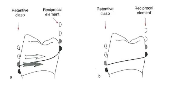
5. Engagement15
Components must encircle more than 180° of the tooth to prevent movement of the abutment out of the assembly.
- Clasp Tip Position: Should be positioned toward the distal (not mid-buccal) to ensure the required 180-degree encirclement.
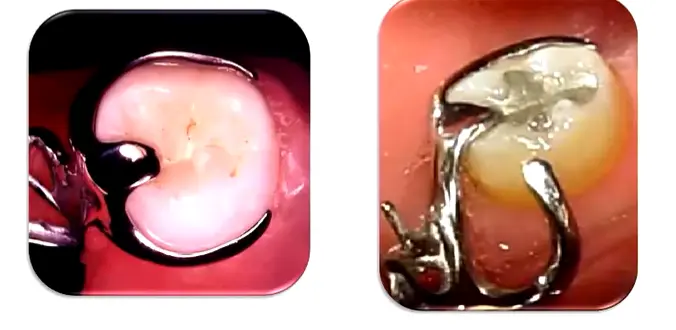
6. Passivity16
When fully seated, the clasp assembly exerts no force on the tooth.
- if there is constant pressure you may end up daamging the pdl
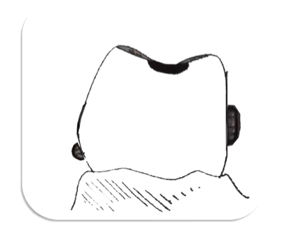
Retention Arm17
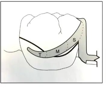
Correct Location
- Middle and/or gingival third.
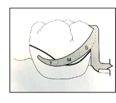
Sections of the Arm
- Shoulder (S)
- Midsection (M)
- Terminal third (T): Flexible clasp terminus located below the height of contour (retentive area).
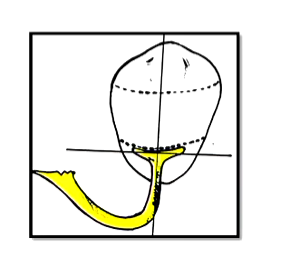
Shape18
- Tapered uniformly.
- Cross-sectional form: half-round form.
- Flexion Plane: The flat side of the half-moon shape faces the tooth to direct flexion in one plane and prevent permanent deformation.
Flexibility19
Flexibility is the capacity to suffer elastic deformation. Factors include:
- Length of the arm: Longer arms are more flexible.
- Circumferential: Measured from the point of origin in the clasp body.
- Bar clasp: Measured from the metal or resin base.
- Degree of taper: Both lengthwise and widthwise.
- Cross-section form
- Diameter: Greater diameter results in less flexibility.
- type of material
Material Properties Affecting Flexibility20
- All cast alloys show some degree of flexibility.
- Cast gold alloys have greater resiliency than Chrome-Cobalt (Cr-Co) alloys.
- Cast
- Cast Clasps: Fabricated from cobalt-chrome (0.25mm undercut) or gold alloys (0.5mm undercut due to superior flexibility).
- Wrought Wire Indications: Used for acrylic dentures or mobile teeth to reduce load on compromised periodontal ligaments. alloy flexibility is inversely proportional to bulk.
- Wrought wire clasps have higher tensile strength than cast clasps. They can be used in smaller diameters to provide greater flexibility without fatigue and fracture.
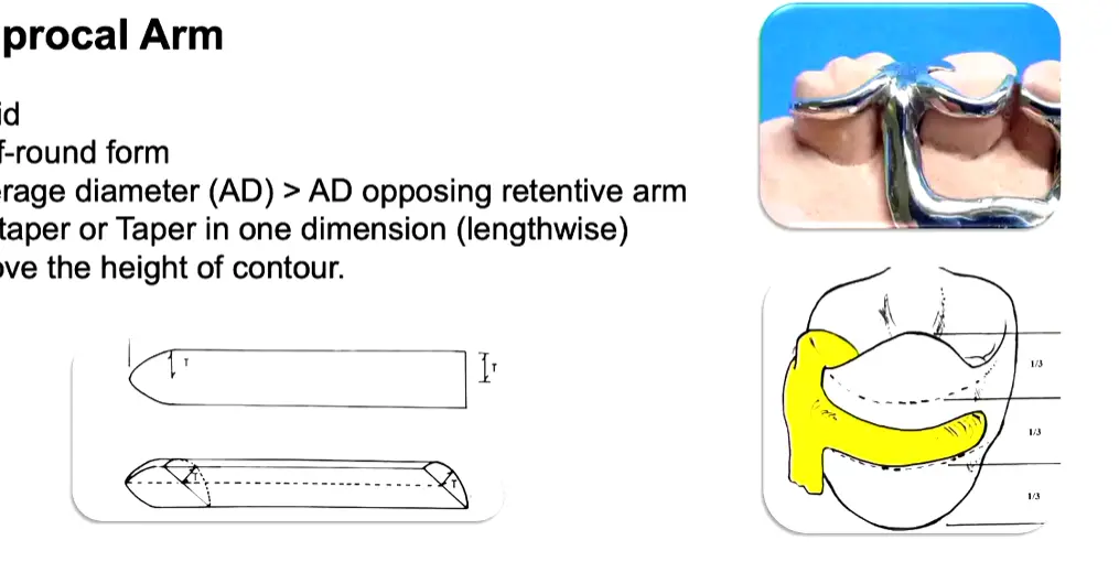
Reciprocal Arm21
- Resists tooth movement in response to deformation of the retentive arm.
- Must be in contact during the entire period of retentive clasp deformation.
- ==usually the lab will take care of this
- Stabilizes the framework against horizontal movements during deformation of the retentive arm.
Physical Characteristics22
- Rigid construction.
- Half-round form.
- Average diameter (AD) is greater than the AD of the opposing retentive arm.
- No taper, or taper in only one dimension (lengthwise).
- Positioned above the height of contour.
Clasp Body23
- Represents the union of arms and rest to the framework.
- Positioned above the height of contour.
- Bracing Design: Features parallel sides (not tapered) from the gingival to the occlusal margin to maintain continuous contact during retentive arm deformation.
- Rigid structure.
- Contacts guiding planes to provide frictional retention.
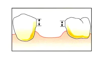
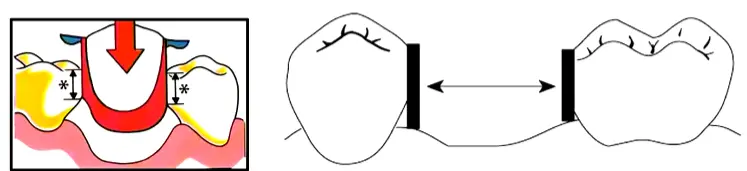
Guiding Planes24
- Flat parallel surfaces prepared on abutment teeth (occlusal one-third to two-thirds).
- Provide a single Path of Insertion (POI).
- Used to control and limit the directions of movement of the RPD during insertion, removal, or function.
- Denture components initiate contact with abutments at the guiding plane area.
Optimal Characteristics of guide planes 25
Guiding planes are most effective when they:
- Are parallel.
- Include more than one common axial surface (e.g., proximal and lingual surfaces).
- Are placed on several teeth.
- Cover a large surface area (long and/or broad).
- Dimensions: Requires a minimum 2–3mm vertical height; 1mm is insufficient for effective guidance.
- Preparation: Created using parallel diamond burs (not taper burs) to ensure flat, parallel walls.
- Clinical Consideration: If a tooth is severely tilted, a survey crown is indicated as guide plane preparation alone may be insufficient.
Types of Clasp Assemblies26
Clasp assemblies are categorized based on the position and approach of the retentive arm:
- Suprabulge
- Infrabulge
Suprabulge Clasps
Circumferential Clasps
- Continuous contact with the crown.
- Approaches from occlusal to gingival.
- Retention arm must be pulled over the height of contour.
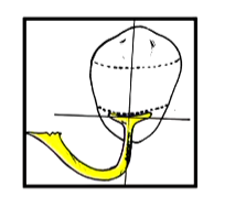
Infrabulge Clasps
Bar Clasps
- Short contact of the retentive arm with the crown.
- Approaches from gingival to occlusal.
- Retention arm must be pushed over the height of contour.
Circumferential Clasps27
Simple Circumferential Design
- The most simple and versatile clasp.
- Assembly consists of one retentive arm opposed by a reciprocal arm originating from the rest.
Indications:
- Molars and premolars.
- Intercalated edentulous areas.
- Canines where there are no aesthetic restrictions.
Limitations:
- Not ideal if the abutment is tilted toward the edentulous space.
Reverse Circumferential Design28
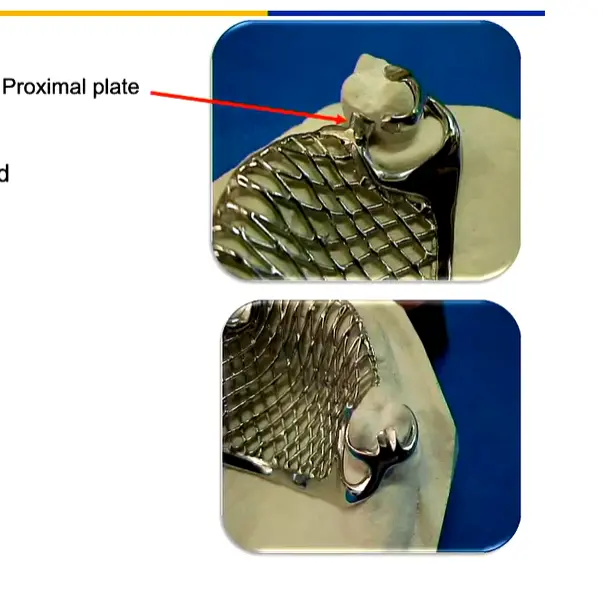
- Rest and body are located opposite to the edentulous area; arms run towards the edentulous space.
- Requires a proximal plate.
Indications:
- Abutment is tilted toward the edentulous space.
Limitations:
- Short clinical crowns.
- Lack of space for the connector.
Ring Clasp Design29
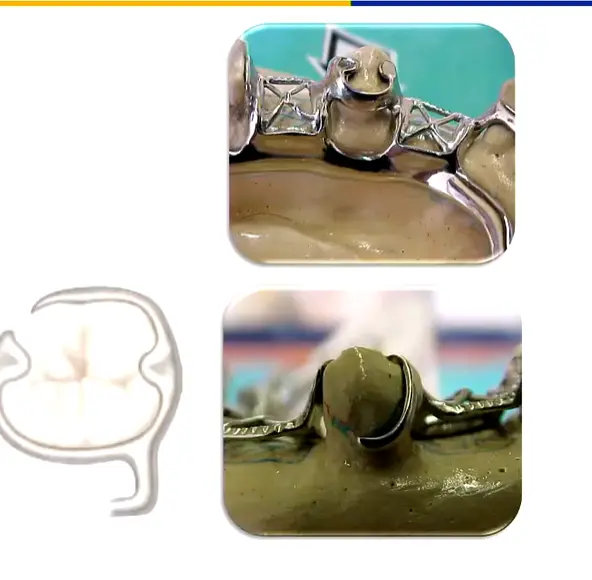
- Features mesial and distal rests.
- Encircles nearly the entire tooth.
Indications:
- Intercalated edentulous areas.
- Molars tipped in a mesiolingual direction.
Limitations:
- Not suitable for free-end saddles.
Embrasure Clasp Design30
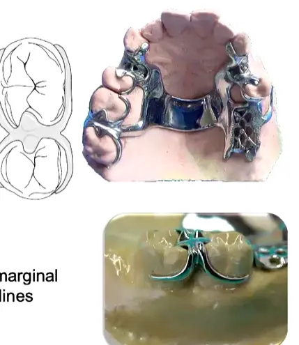
- Essentially two simple circumferential clasps joined at the bodies.
- Requires sufficient occlusal clearance through the embrasure.
- Occlusal rest seats must not create wedging forces between teeth.
- Biomechanics: Ideally positioned perpendicular to the fulcrum line for maximum indirect retention effect.
Indications:
- Indirect retention.
- Molars and premolars.
Limitations:
- Requires extensive preparation of marginal ridges, involving facial inclines.
Bar Clasps31
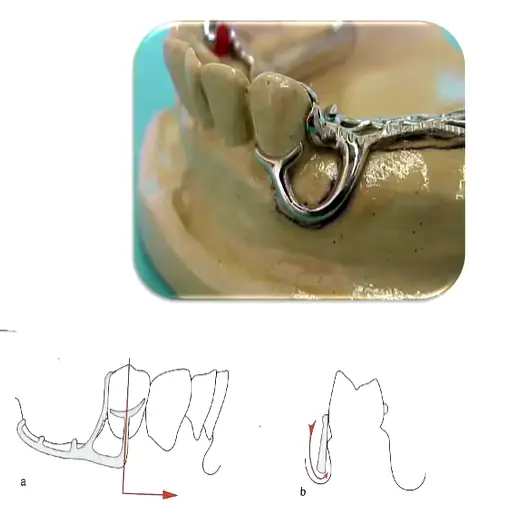
T-Clasp Design32
- Approach arm originates from components in the edentulous area.
- Retention arm crosses the gingival margin at 90°.
- Features two horizontal projections.
Indications:
- Intercalated or free-end edentulous areas.
Limitations:
- Potential interference with the frenulum.
- Severe soft tissue undercuts (risk of food entrapment and irritation).
- Height of contour located near the occlusal surface.
- Design Detail: Features a horizontal bar with a vertical retentive tip resembling a “T”.
Modified T-Clasp Design33
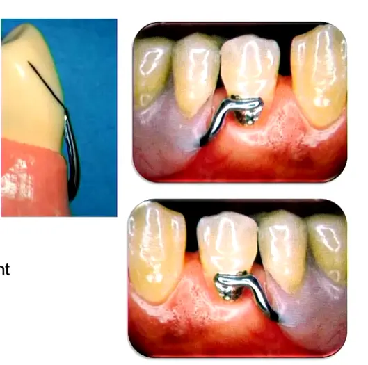
- Features only one horizontal projection.
- Designed to avoid significant soft tissue undercuts.
Indications:
- Intercalated or free-end edentulous areas.
Limitations:
- Interference with frenulum.
- Severe soft tissue undercut (risk of food entrapment and soft tissue irritation).
- Height of contour near the occlusal surface.
I-Clasp Design34
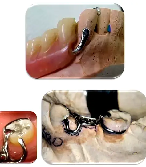
- Crosses perpendicular to the gingival margin.
- Should be placed mesially to the midfacial prominence of the abutment.
Indications:
- Intercalated or free-end edentulous areas.
Limitations:
- Interference with frenulum.
- Severe soft tissue undercut (risk of food entrapment and soft tissue irritation).
- Height of contour near the occlusal surface.
RPI Clasp Design35
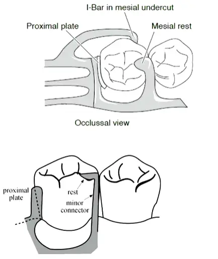
- Comprises a Rest (R), Proximal plate (P), and I-bar (I).
- The I-bar is located in the mesio-buccal undercut.
- Requires preparation of guiding planes.
- Reciprocation: Unique because it has no separate reciprocal arm; the mesial rest and distal proximal plate together provide reciprocation.
- Contraindications: Canines and incisors, as the emergence profile prevents adequate proximal plate preparation without compromising aesthetics.
Indications:
- Kennedy Class I and II.
Limitations:
- Requires reduction of tooth structure.
- Tipped teeth may require severe axial reduction.
Proximal Plate in RPI Clasp36
- A wide minor connector touching the distal guiding plane.
- Located at the junction of the occlusal and middle third of the guiding plane.
- Approximately 1 mm thick.
- Joins the framework at a right angle.
Benefits of Proximal Plate37
- Improves stabilization of the prosthesis.
- Improves retentiveness by limiting the path of insertion and removal.
- Provides reciprocation.
- Reduces food impaction (when guide planes are properly prepared).
Note: These benefits are not achieved without proper guiding plane preparation.
Telescopic Crown Retained Removable Partial Dentures38
Retention Principles
- Utilizes parallel-sided inner and outer crowns.
- Rigidly connected to the abutment teeth.
- Design: Primary coping (inner crown) with parallel walls cemented to the prepared tooth; secondary crown (telescopic crown) attached to the RPD
- Retention: Purely frictional through precise parallelism of the inner surfaces
- Function: Allows only vertical path of removal; resists oblique and horizontal forces during function
- Requirements: Very precise preparation; often requires tall crowns, sometimes necessitating elective endodontics to achieve adequate reduction
Considerations
- High treatment costs.
- Increased risk for tooth fracture.
- Treatment and laboratory procedures are highly complex.
(Reference: Wostmann et al. 2007)
Aesthetic Clasps39
Flexible Removable Partial Dentures
Utilize thermoplastic materials such as:
- Nylon
- Acetal resin (Polyoxymethylene)
- PMMA
- Polypropylene
(Reference: Hill et al. 2013)
PEEK Clasps40
CAD-CAM Partial Dentures
- PEEK offers good mechanical and biological properties.
- Denture clasps made of PEEK have lower retentive forces compared to cobalt–chromium (Co–Cr) clasps.
- Current Status: Work in progress; not yet clinically acceptable for long-term stability and retention due to material limitations in clasp design
- Future Applications: Potential for full framework milling in tooth-colored materials to eliminate metal display entirely
(Reference: Najeeb et al. 2016)
Retainers are essential components used to maintain the position of teeth after orthodontic treatment has been completed. They ensure that the corrected alignment is preserved while the surrounding bone and gingival tissues adapt to the new tooth positions.
Types of Retainers
-
Fixed Retainers
- Typically consist of a stainless steel wire bonded to the lingual surface of the anterior teeth.
- Commonly used for the mandibular arch to prevent relapse of lower incisor crowding.
- Provide continuous retention without requiring patient compliance for insertion or removal.
-
Removable Retainers
- Hawley Retainers: Constructed from acrylic and metallic wires (labial bow and clasps). They are durable and allow for minor adjustments to tooth position.
- Vacuum-Formed Retainers (VFRs): Clear, plastic appliances that cover the entire dental arch. They are highly esthetic and popular among patients due to their near-invisibility.
Clinical Considerations
- Duration of Wear: The retention phase is often long-term. Initially, full-time wear may be required, followed by a transition to nighttime-only wear as the occlusion stabilizes.
- Maintenance and Hygiene: Patients must be instructed on proper cleaning techniques to prevent plaque accumulation and dental caries, particularly around fixed retainer wires.
- Follow-up Appointments: Regular monitoring is necessary to ensure the integrity of the retainer and to check for any signs of dental relapse.
Clinical Implementation Notes
- Guide planes must be parallel and adequate in height (2–3mm)
- Retention must be balanced across all abutments
- The RPI system is contraindicated for canines/incisors due to emergence profile limitations
- Infrabulge clasps are preferred for free-end saddles due to their stress-releasing properties during function
- Survey crowns may be necessary when tooth tilt or anatomy precludes proper clasp engagement or guide plane preparation
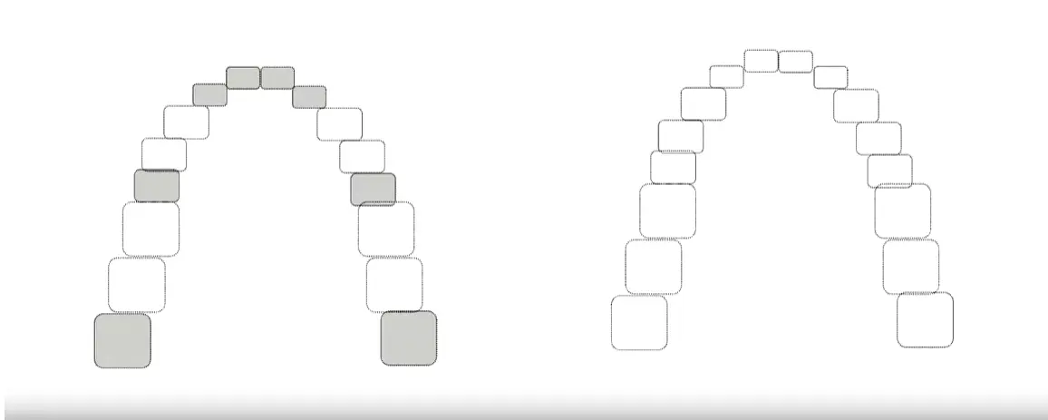
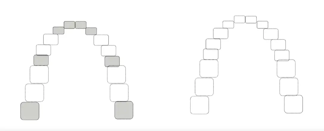
Which Clasps to use for these cases? case practiceProblem
Footnotes
-
Original PDF page 1: L4 Clasp Assembly, p.1 ↩
-
Original PDF page 41: L4 Clasp Assembly, p.41 ↩
-
Original PDF page 2: L4 Clasp Assembly, p.2 ↩
-
Original PDF page 3: L4 Clasp Assembly, p.3 ↩
-
Original PDF page 4: L4 Clasp Assembly, p.4 ↩
-
Original PDF page 5: L4 Clasp Assembly, p.5 ↩
-
Original PDF page 6: L4 Clasp Assembly, p.6 ↩
-
Original PDF page 7: L4 Clasp Assembly, p.7 ↩
-
Original PDF page 8: L4 Clasp Assembly, p.8 ↩
-
Original PDF page 9: L4 Clasp Assembly, p.9 ↩
-
Original PDF page 10: L4 Clasp Assembly, p.10 ↩
-
Original PDF page 11: L4 Clasp Assembly, p.11 ↩
-
Original PDF page 12: L4 Clasp Assembly, p.12 ↩
-
Original PDF page 13: L4 Clasp Assembly, p.13 ↩
-
Original PDF page 14: L4 Clasp Assembly, p.14 ↩
-
Original PDF page 15: L4 Clasp Assembly, p.15 ↩
-
Original PDF page 16: L4 Clasp Assembly, p.16 ↩
-
Original PDF page 17: L4 Clasp Assembly, p.17 ↩
-
Original PDF page 18: L4 Clasp Assembly, p.18 ↩
-
Original PDF page 19: L4 Clasp Assembly, p.19 ↩
-
Original PDF page 20: L4 Clasp Assembly, p.20 ↩
-
Original PDF page 21: L4 Clasp Assembly, p.21 ↩
-
Original PDF page 22: L4 Clasp Assembly, p.22 ↩
-
Original PDF page 23: L4 Clasp Assembly, p.23 ↩
-
Original PDF page 24: L4 Clasp Assembly, p.24 ↩
-
Original PDF page 25: L4 Clasp Assembly, p.25 ↩
-
Original PDF page 27: L4 Clasp Assembly, p.27 ↩
-
Original PDF page 28: L4 Clasp Assembly, p.28 ↩
-
Original PDF page 29: L4 Clasp Assembly, p.29 ↩
-
Original PDF page 30: L4 Clasp Assembly, p.30 ↩
-
Original PDF page 31: L4 Clasp Assembly, p.31 ↩
-
Original PDF page 32: L4 Clasp Assembly, p.32 ↩
-
Original PDF page 33: L4 Clasp Assembly, p.33 ↩
-
Original PDF page 34: L4 Clasp Assembly, p.34 ↩
-
Original PDF page 35: L4 Clasp Assembly, p.35 ↩
-
Original PDF page 36: L4 Clasp Assembly, p.36 ↩
-
Original PDF page 37: L4 Clasp Assembly, p.37 ↩
-
Original PDF page 38: L4 Clasp Assembly, p.38 ↩
-
Original PDF page 39: L4 Clasp Assembly, p.39 ↩
-
Original PDF page 40: L4 Clasp Assembly, p.40 ↩