Removable Partial Denture: Clinical and Laboratory Steps
Oral Health Centre of Western Australia1
This document outlines the clinical and laboratory procedures involved in the fabrication of a Removable Partial Denture (RPD).
Lead Clinician:
- Dr. Matsubara
Initial Examination and Study Models
Patient History and Expectations2
- Presenting complaint and its history
- Medical history (including medications)
- Dental history (previous prosthesis)
- Patient expectations
- Commitment and Psychology
- Success relies on patient willingness to wear the device
- Psychological aspects like depression may interfere with adaptation
Clinical Examination
Oral Examination Components
- Temporomandibular Joint (TMJ) and Muscles of Mastication (MoM)
- Occlusion
- Vitality of strategic teeth
- Periodontal assessment of abutment teeth
- Assessment of soft tissues
- Preparation for study models on articulator
- Prosthetic Space Assessment
- Study models on articulator check space for framework, rests, and artificial teeth
Study Models and Articulator Mounting
Workflow for Study Models3
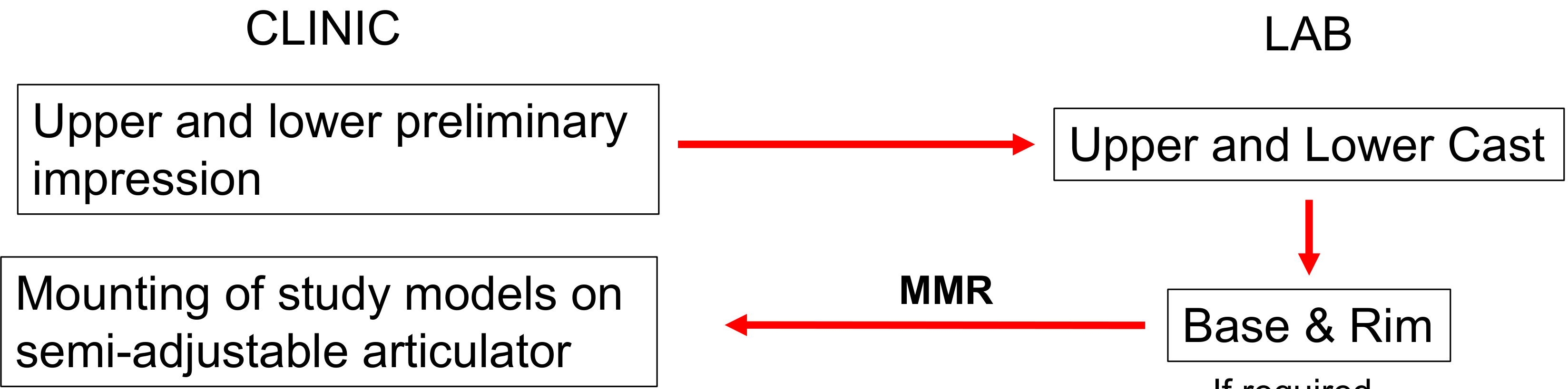
- Clinical Phase: Upper and lower preliminary impressions are taken.
- Laboratory Phase: Fabrication of upper and lower casts.
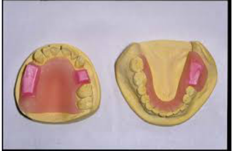
- Laboratory Phase (If required): Fabrication of base and rim.
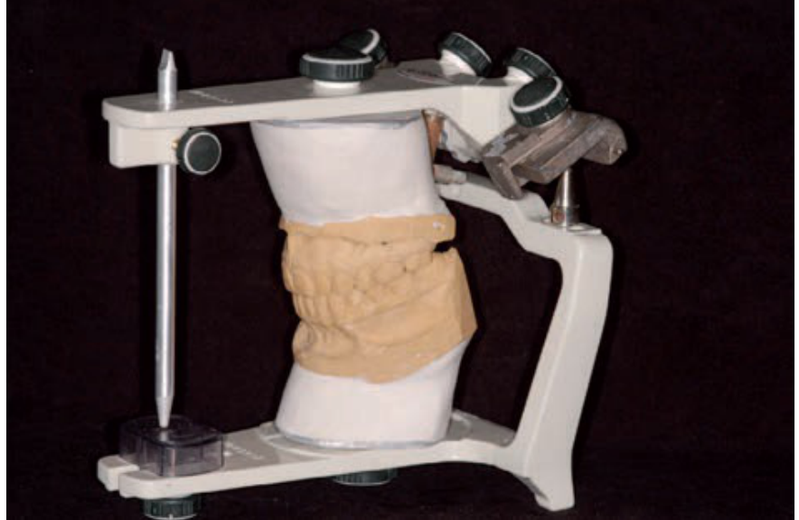
- Clinical/Laboratory Interface: Maxillo-Mandibular Relationship (MMR) records are used for mounting study models on a semi-adjustable articulator.
- Impression and Mounting Details
- Preliminary impression uses alginate and stock tray (periphery wax for support)
- Laboratory Phase: Gypsum type 3 used for study models
- Maxillary model mounted freehand or with face bow (more accurate)
- Mandibular model requires bite registration
Recording Centric Relation and Occlusal Vertical Dimension
Tools for Centric Relation
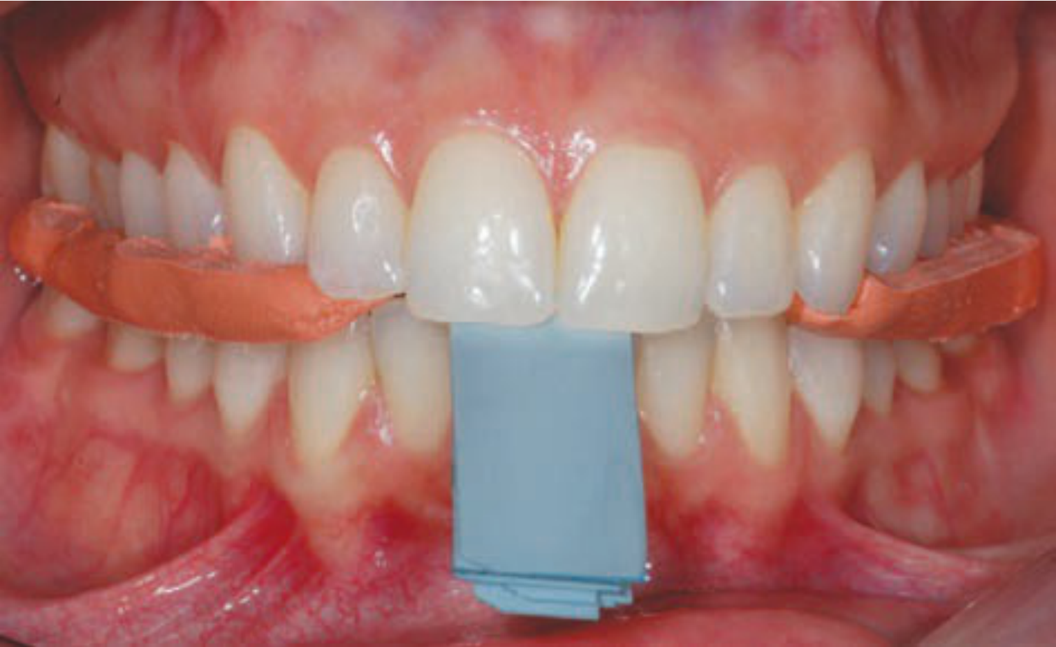
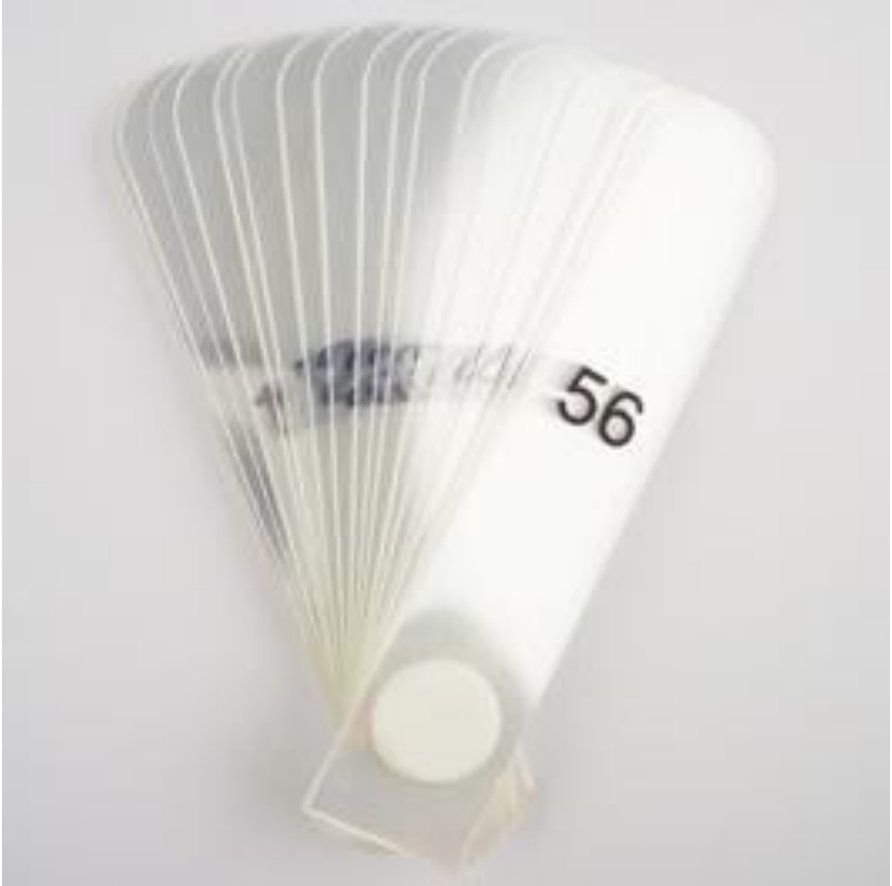
- Leaf gauge (each leaf measures 200 µm)
- Approach Types
- Confirmative: Record bite in maximum intercuspation (MIP)
- Reorganize: Specific techniques required to increase vertical dimension
- Leaf Gauge Caution
- Do not bite too hard (drives mandible to uncomfortable retruded position)
- Indicated for asymptomatic patients; use anterior jig/splint for TMD symptoms
Vertical Dimension Considerations
- Assessment for the increase of Occlusal Vertical Dimension (OVD)
Measurement Instrumentation
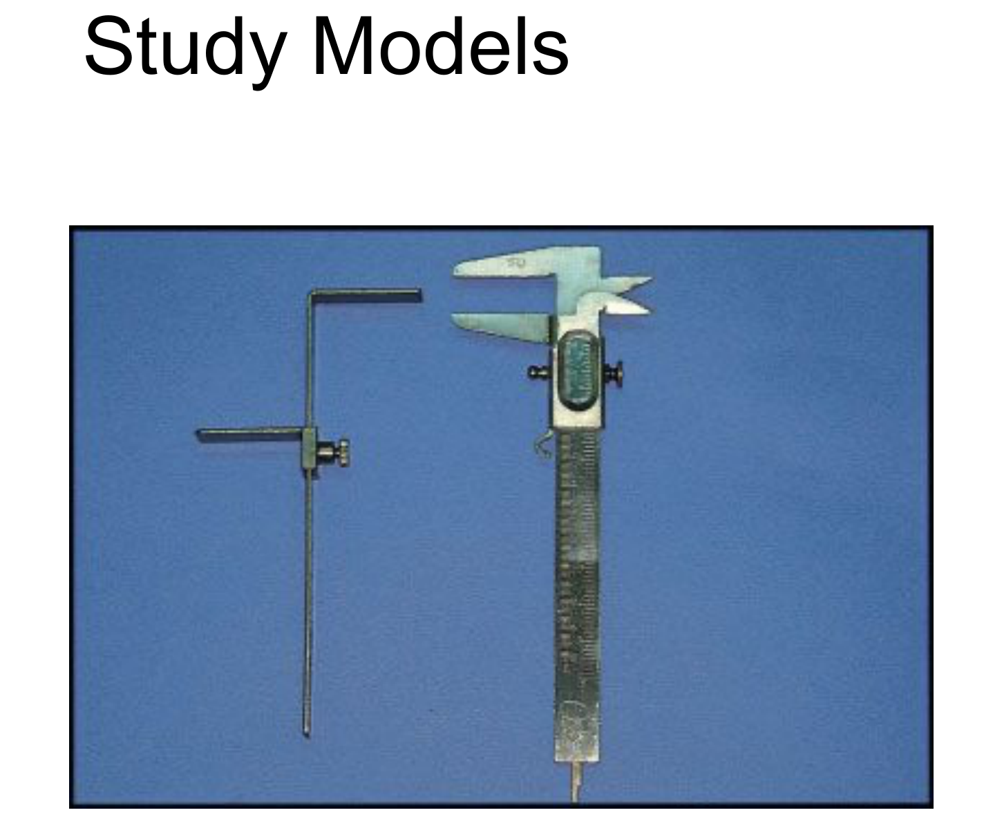
- Willis bite gauge
- Calipers
- Compass
Vertical Dimension Calculation
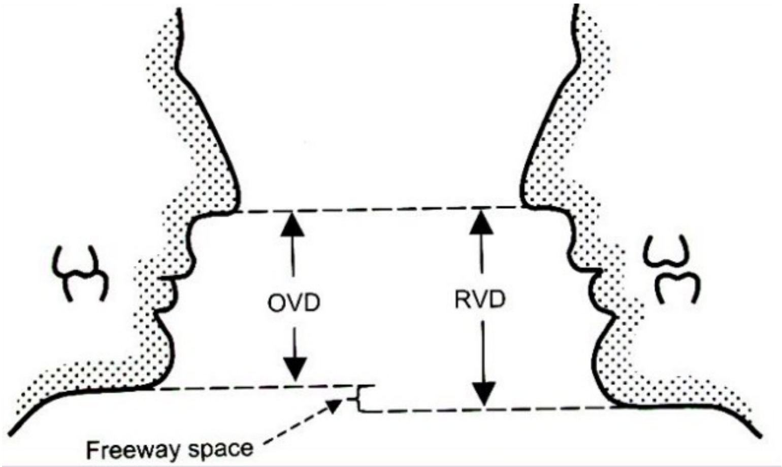
- The formula for determining Occlusal Vertical Dimension is: OVD = RVD – Freeway space
- This involves measuring the Resting Vertical Dimension (RVD) and accounting for the necessary clearance.
Case Study: Establishing OVD Without Anterior Teeth
When anterior teeth are missing, the leaf gauge cannot be used.
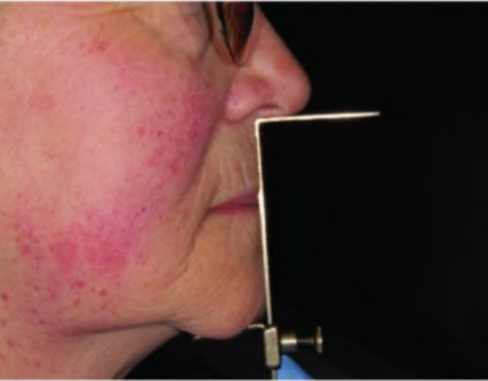
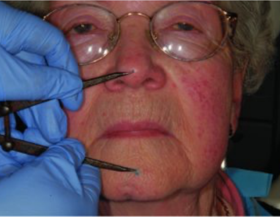
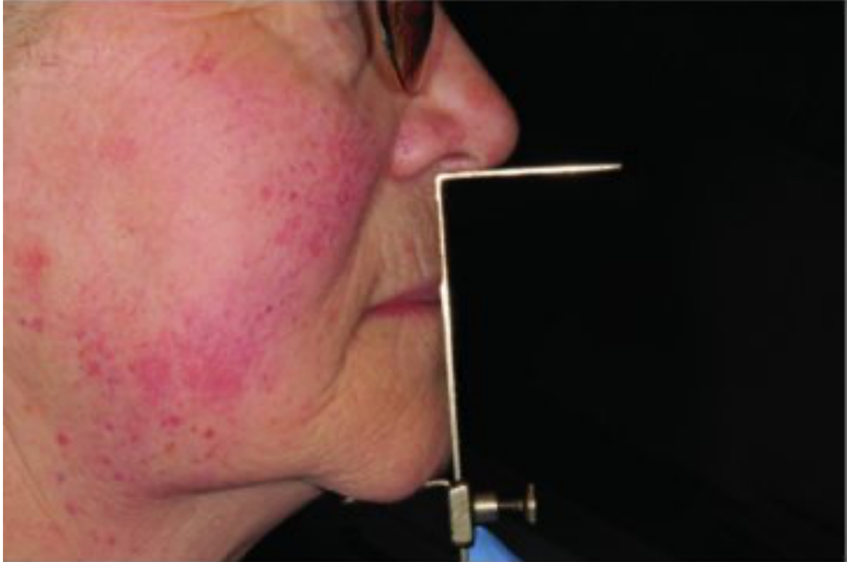
- Use base and rim with extraoral references (base of nose to chin)
- Measure Rest Vertical Dimension (RVD) and subtract freeway space (average 3mm)
- Verify with multiple methods for accuracy
Phonetics Tests for Occlusal Vertical Dimension
Speaking Method Assessment
- Utilization of sibilant phonemes (the “S” sound).
- Observation of the “closest speaking space,” typically requiring 2-3 mm between the incisors.
- Specific Test
- Ask patient to pronounce "Mississippi 66"
- Consistency Check
- Closest speaking space is more consistent than freeway space (varies with stress)
Diagnostic Workup and Wax-Up
Diagnostic Procedures
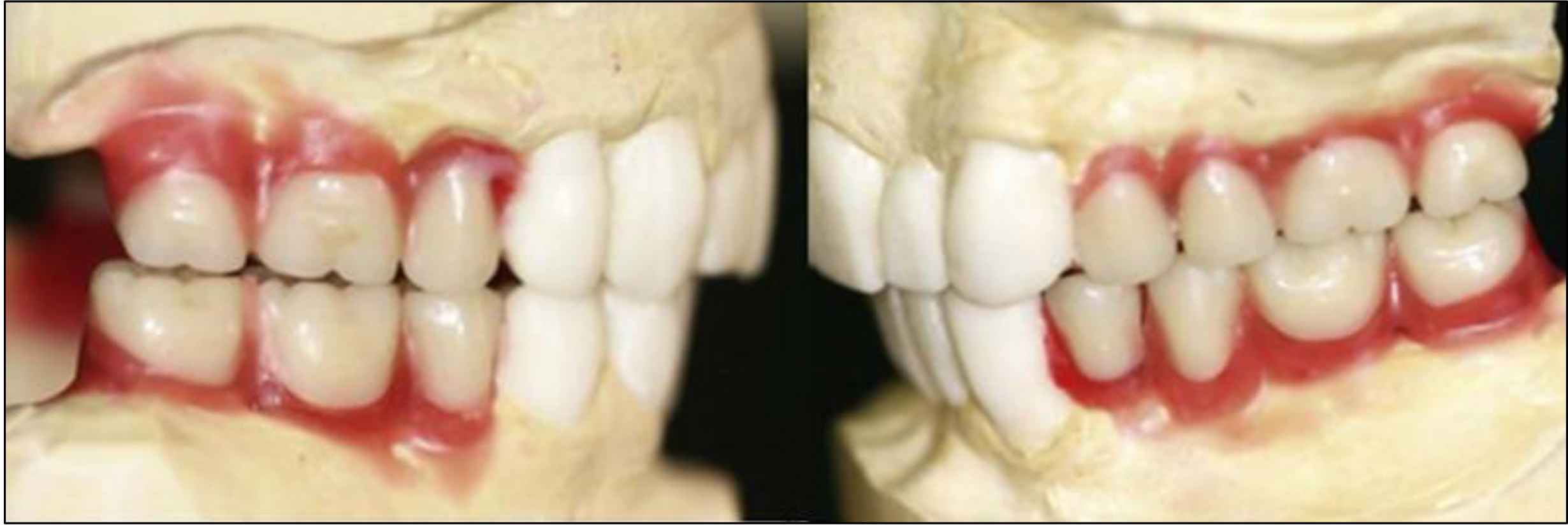
- Simulate the final teeth position.
- Perform a wax-up for crowns and identify necessary changes to the occlusal plane.
- Plan for survey crowns.
- Model Duplication
- Duplicate models before mounting
- One model mounted for study; other used to survey and design framework
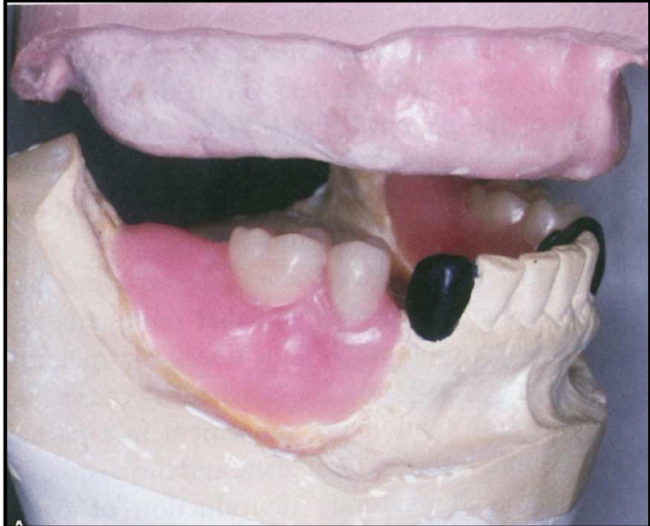
Mouth Preparation and Workflow Overview
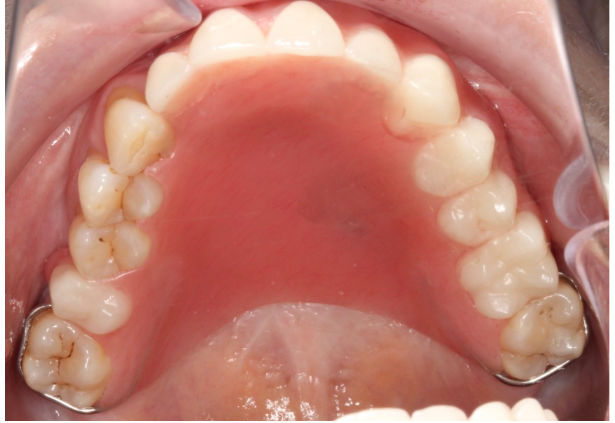
Following the initial survey and design on the study model, the clinical phase of mouth preparation begins. This phase ensures the oral environment is optimized for the prosthesis.
- Adjust height of contour
- Create guide planes
- Add composite for rest seats
- Create undercuts for retention arms
Clinical Procedures and Requirements4
Mouth Preparation Procedures
- Diagnostic Aids: Preparation of an additional study model to verify changes.
- Pre-prosthetic Treatments:
- Endodontic treatment
- Periodontal treatment
- Direct restorations
- Abutment Modifications:
- Preparation of guiding planes
- Preparation of rest seats
- Fabrication of survey crowns
Survey Crown Sequence
Survey crowns must be fabricated and inserted before starting framework fabrication. Send working model and study model with framework design to the lab.
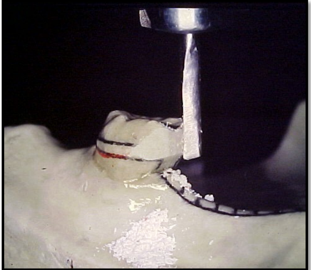
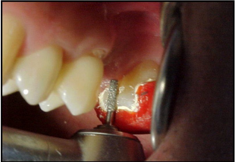
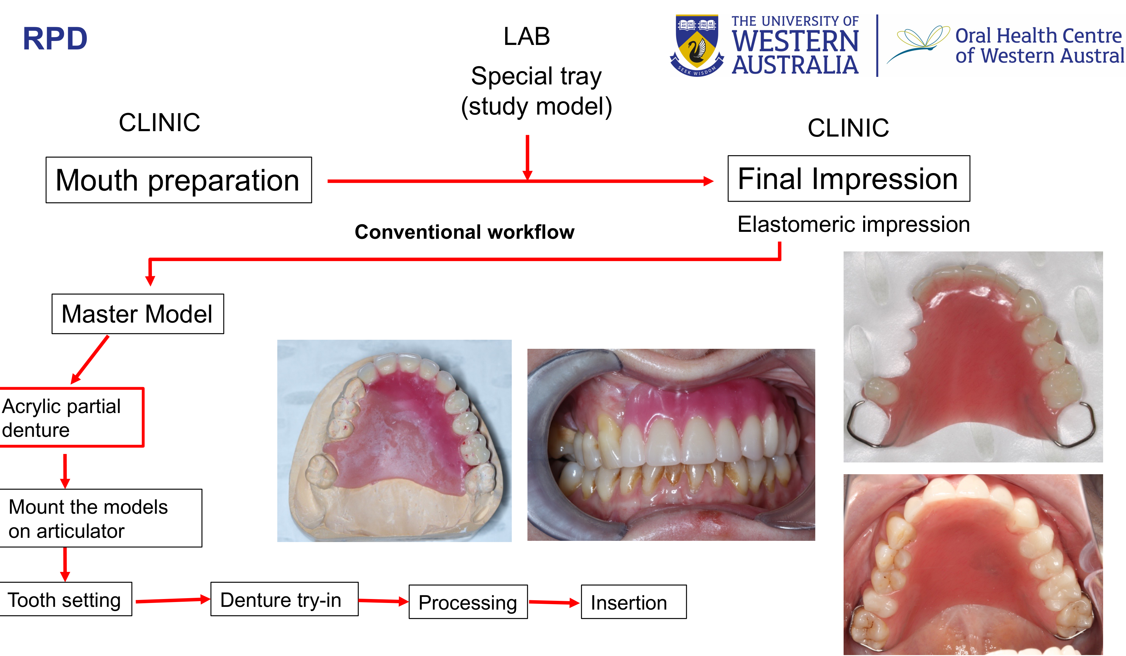
Workflow Pathways for Acrylic and Co-Cr Dentures
The transition from mouth preparation to the creation of the master model follows a standardized clinical and laboratory sequence.
- After mouth preparation, the next step is the final impression using elastomeric material (PVS).
- The impression is beaded, boxed, and poured to create the master model.

Initial Sequence5
- Clinic: Mouth preparation.
- Lab: Fabrication of a special tray on a duplicate study model.
- Clinic: Final
Acrylic Workflow Notes
Mounting requires a face bow. A new base and wax rim must be created for the master model. Clasps are added after processing. If significant changes are needed during try-in, send back to the lab for repositioning. impression using elastomeric material.
Laboratory Requirements by Denture Type
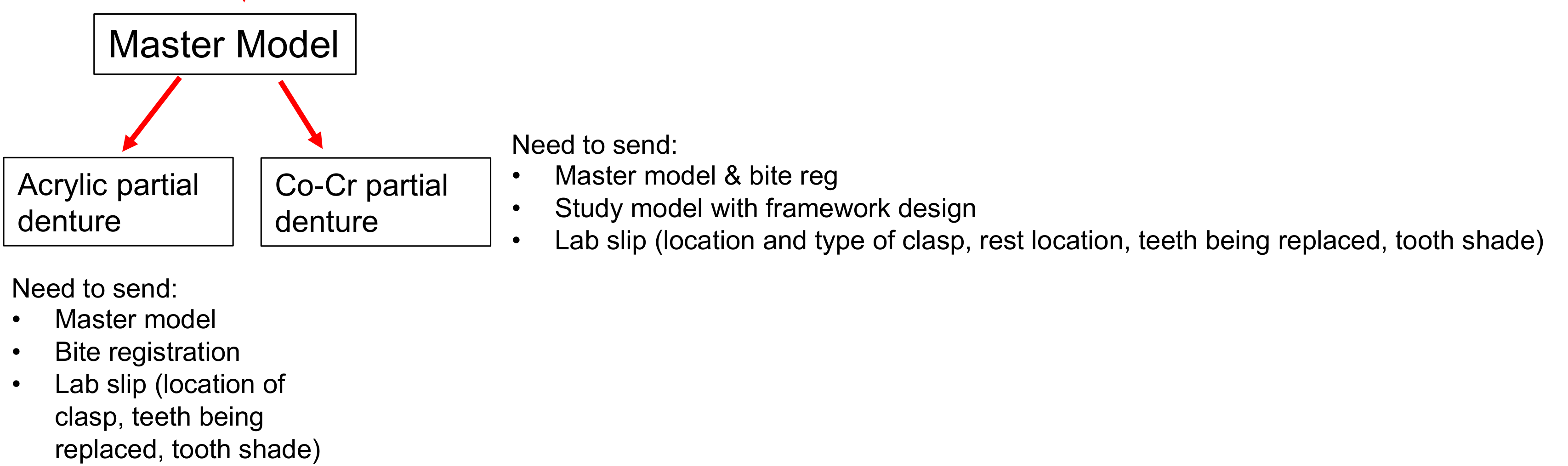
Once the master model is obtained via the conventional workflow, specific items must be sent to the laboratory based on the material choice:
-
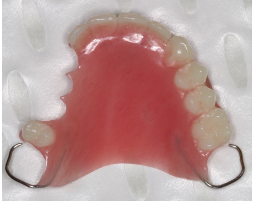
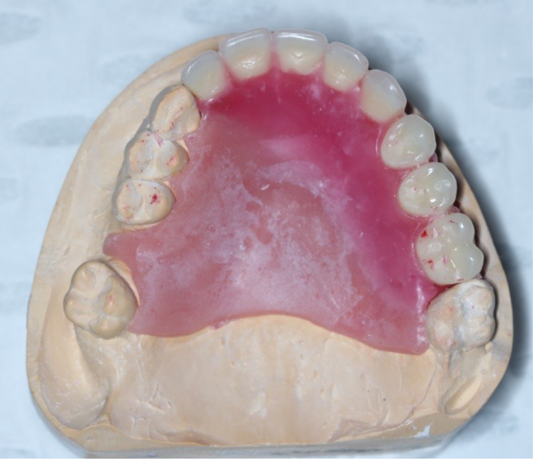
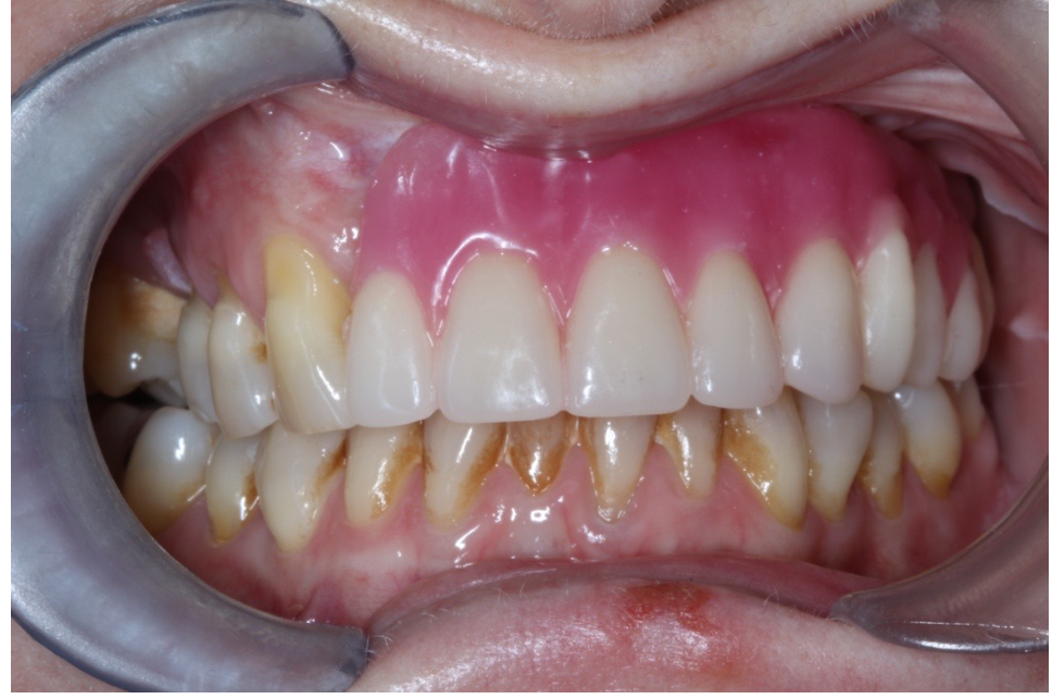
Acrylic Partial Denture:
- Master model
- Bite registration
- Lab slip detailing: location of clasps, teeth being replaced, and tooth shade.
-
Cobalt-Chrome (Co-Cr) Partial Denture:
- Master model and bite registration
- Study model indicating the framework design
- Lab slip detailing: location and type of clasps, rest locations, teeth being replaced, and tooth shade.
- Lab slip must also detail major connector type and clasp type for each abutment.
Acrylic Partial Denture Workflow6
This pathway outlines the specific steps for progressing from the final impression to the insertion of an acrylic prosthesis:
- Clinical Phase: Mouth preparation.
- Laboratory Phase: Fabrication of a special tray using the study model.
- Clinical Phase: Final elastomeric impression.
- Master Model Generation: The master model is produced from the final impression.
- Laboratory/Clinical Progression:
- Mount the models on an articulator.
- Tooth setting.
- Denture try-in.
- Processing.
- Final insertion.
Cobalt-Chrome (Co-Cr) Partial Denture Workflow7
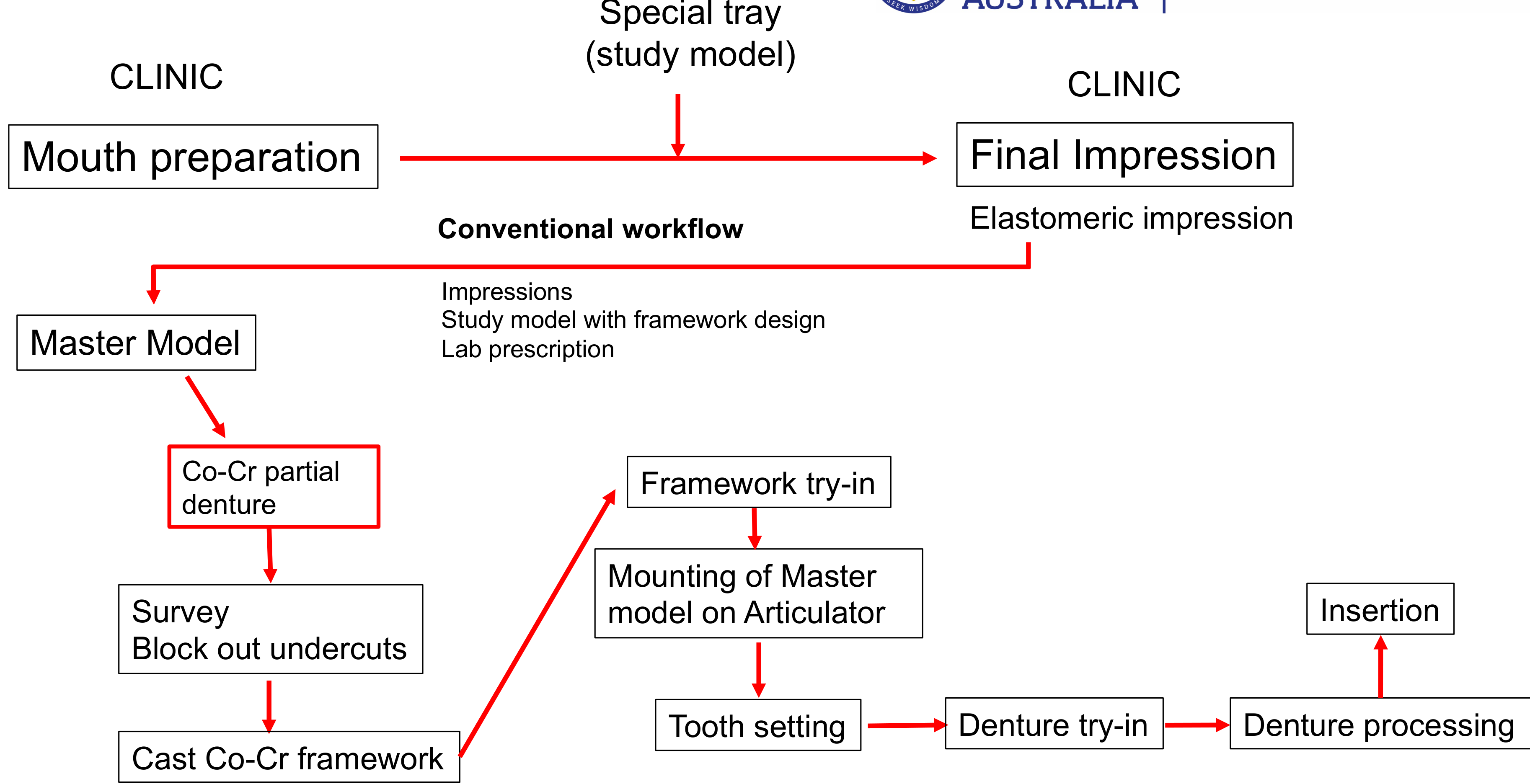
The workflow for Co-Cr dentures involves additional laboratory steps for framework fabrication and clinical verification:
-
Initial Steps:
- Clinic: Mouth preparation.
- Lab: Special tray fabrication (study model).
- Clinic: Final elastomeric impression.
-
Framework Fabrication (Laboratory):
- Utilize the master model, study model with framework design, and lab prescription.
- Surveying and blocking out undercuts.
- Casting the Co-Cr framework.
-
Clinical Verification and Finishing:
- Framework Try-in: Clinical assessment of the cast framework.
- Mounting: Mounting of the master model on the articulator.
- Finalization: Tooth setting Denture try-in Denture processing Insertion
Co-Cr Workflow Details
The master model is duplicated: one for survey/block out, one for processing. Digital Workflow: Impressions can be scanned; frameworks can be 3D printed in wax or castable resin. .
Impressions and Master Cast
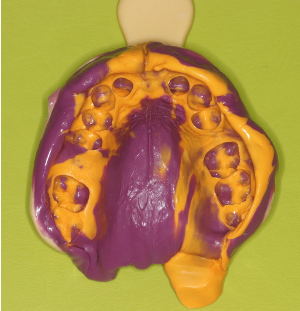
To ensure an accurate elastomeric impression for the fabrication of the Removable Partial Denture (RPD) framework, specific technical requirements must be met regarding the custom tray.
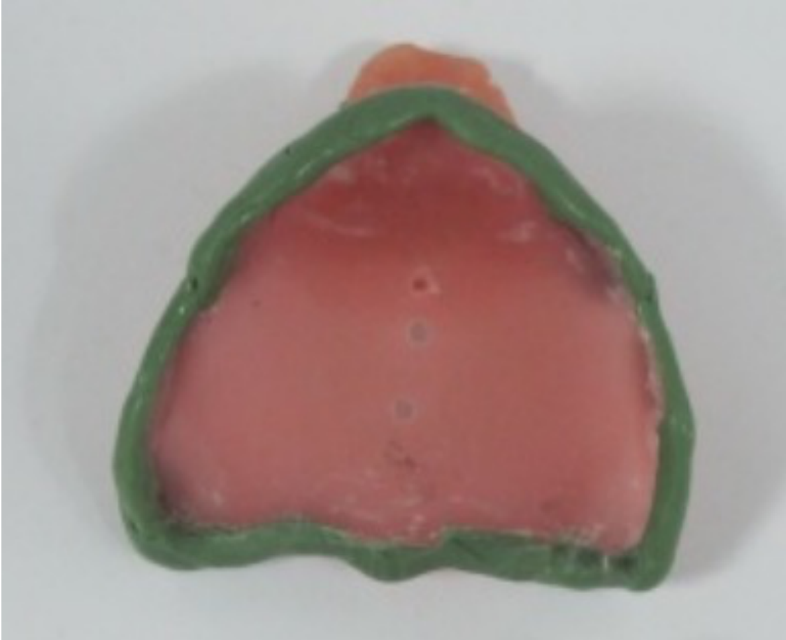
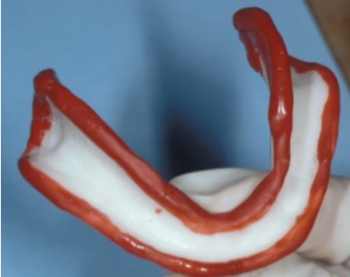
- Border Molding: Steps follow the complete denture exercise (border molding followed by PVS light body).
- Tray Check: Before impression taking, try the custom tray in the mouth to ensure it is not overextended.
- Anatomy: Retract lips and cheeks to copy frenulum insertion and avoid overextending the denture base.
Elastomeric Impression for Framework Fabrication8
Custom Tray Specifications9
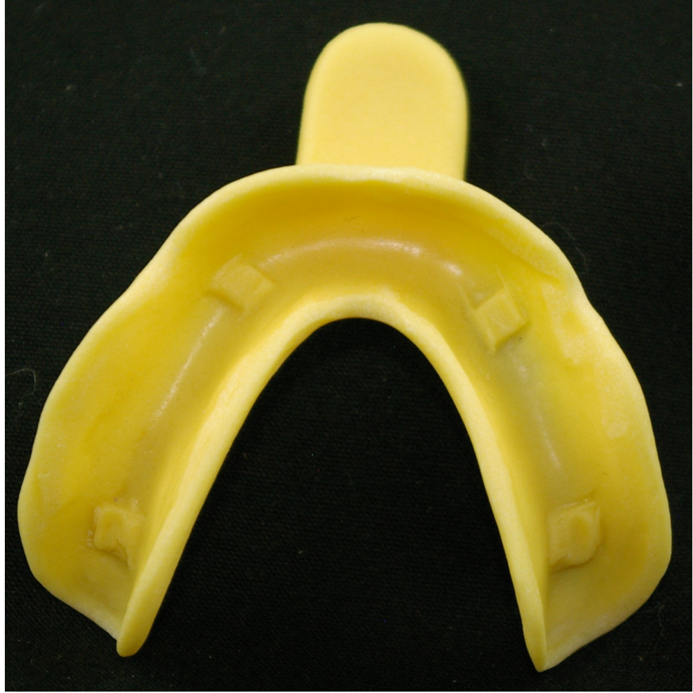
- The thickness of the custom tray border should be maintained at 2-3mm.
- Reasoning: This provides good support for border molding; a very thick tray may compromise the peripheral seal.
- Retention: Suction is helpful for extensive Class 1 or 2 cases with full palatal coverage to provide retention.
- For a visual demonstration of the fabrication process, refer to the video titled “Partial Custom Tray”.
Beading and Boxing the Impression
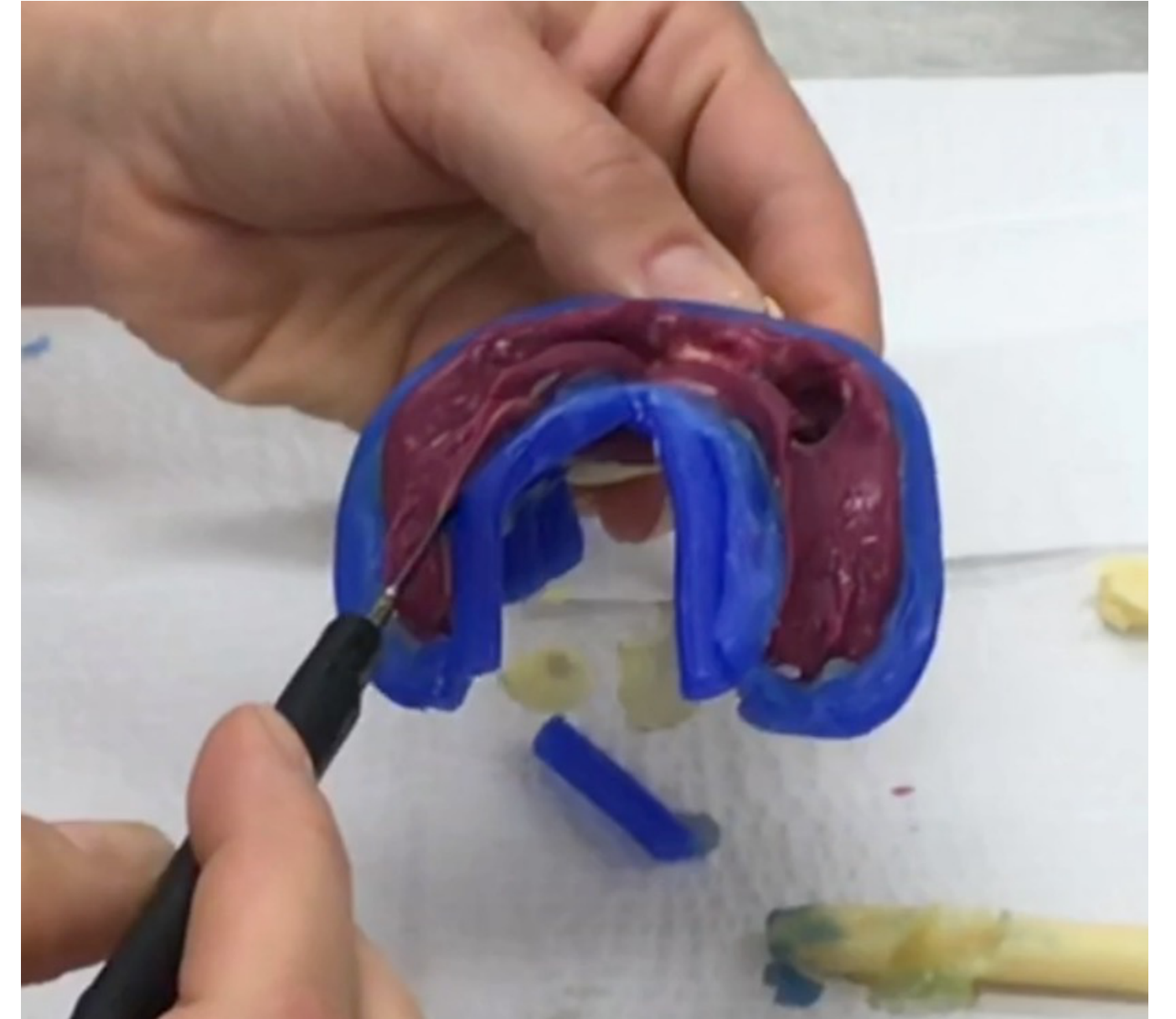
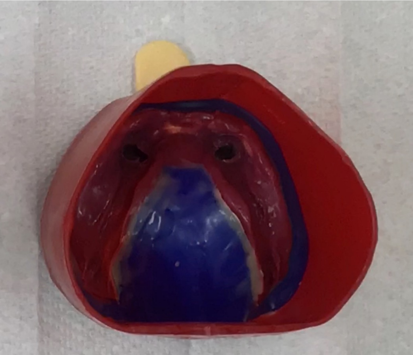
Beading and boxing the impression is a critical step to ensure the accuracy and quality of the master model pour-up.
- Applicability: This step is the same for both partial and complete edentulous final impressions.
Procedural Guidance10
- The process involves preparing the impression borders and creating a containment wall (boxing) to control the flow and thickness of the dental stone.
- For a detailed walkthrough of this laboratory technique, watch the video “Beading and Boxing”.
Master Model Preparation
The preparation of the master model is a multi-step process essential for the design and fit of the final framework.
Master Model Workflow11
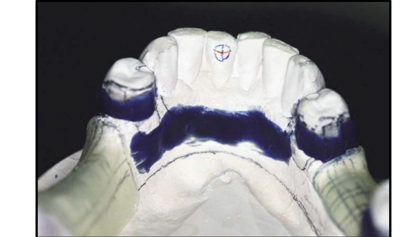
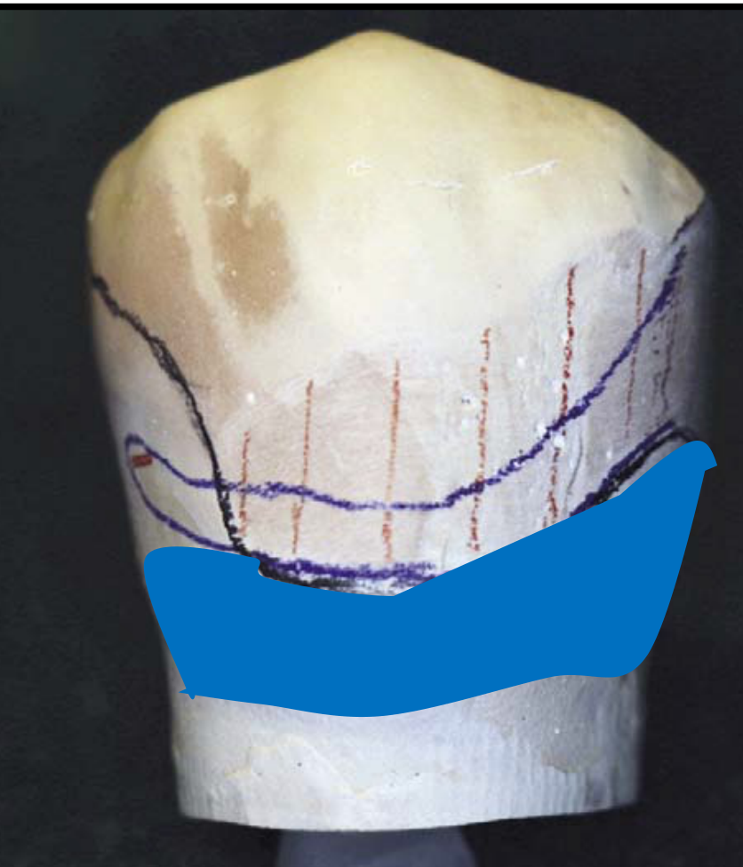
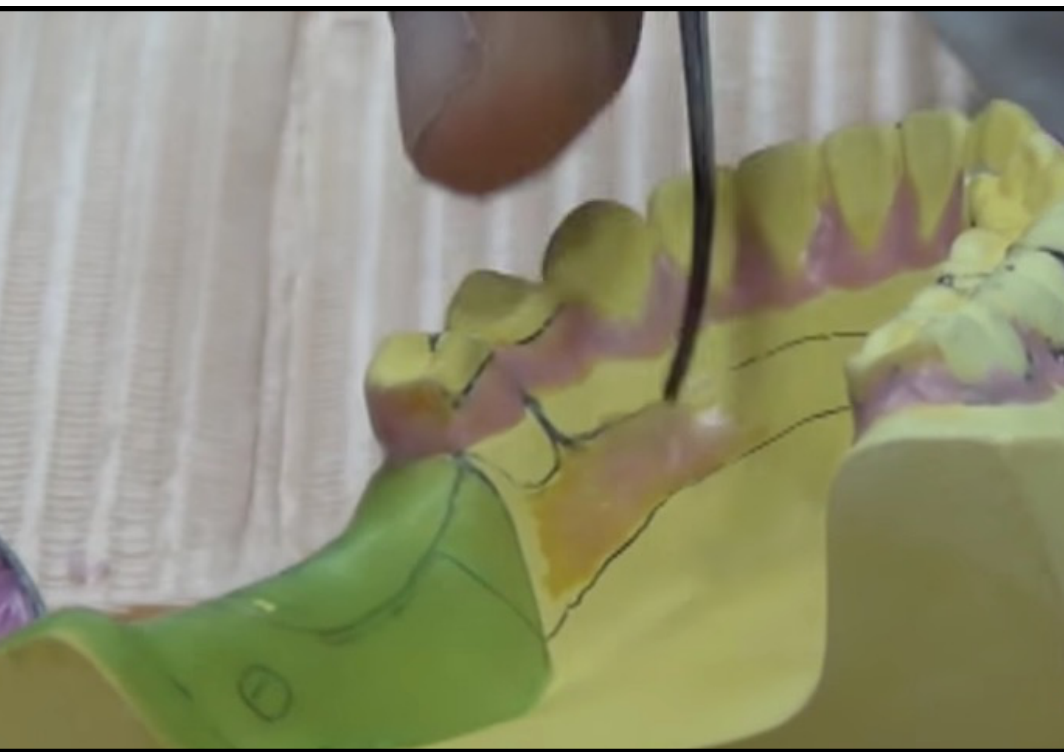
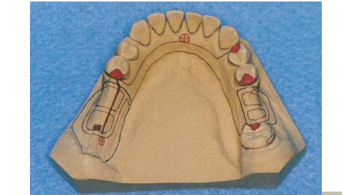
- Surveying: Analyze the master model to determine the path of insertion and identify necessary modifications.
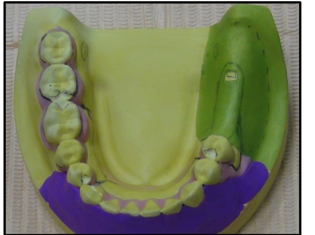
- Block out undercuts: Apply wax to eliminate unwanted undercuts that would interfere with the framework’s fit or removal.
- Duplication: Prepare the modified master model for the duplication process to create the refractory/investment cast.
- Model 1 (Framework): Used to block out undercuts and create the investment model.
- Model 2 (Processing): Used to process the denture after framework try-in.
- Tripodizing: Transfer the three reference points used during the tripod step to the master model so the lab technician can position it identically.
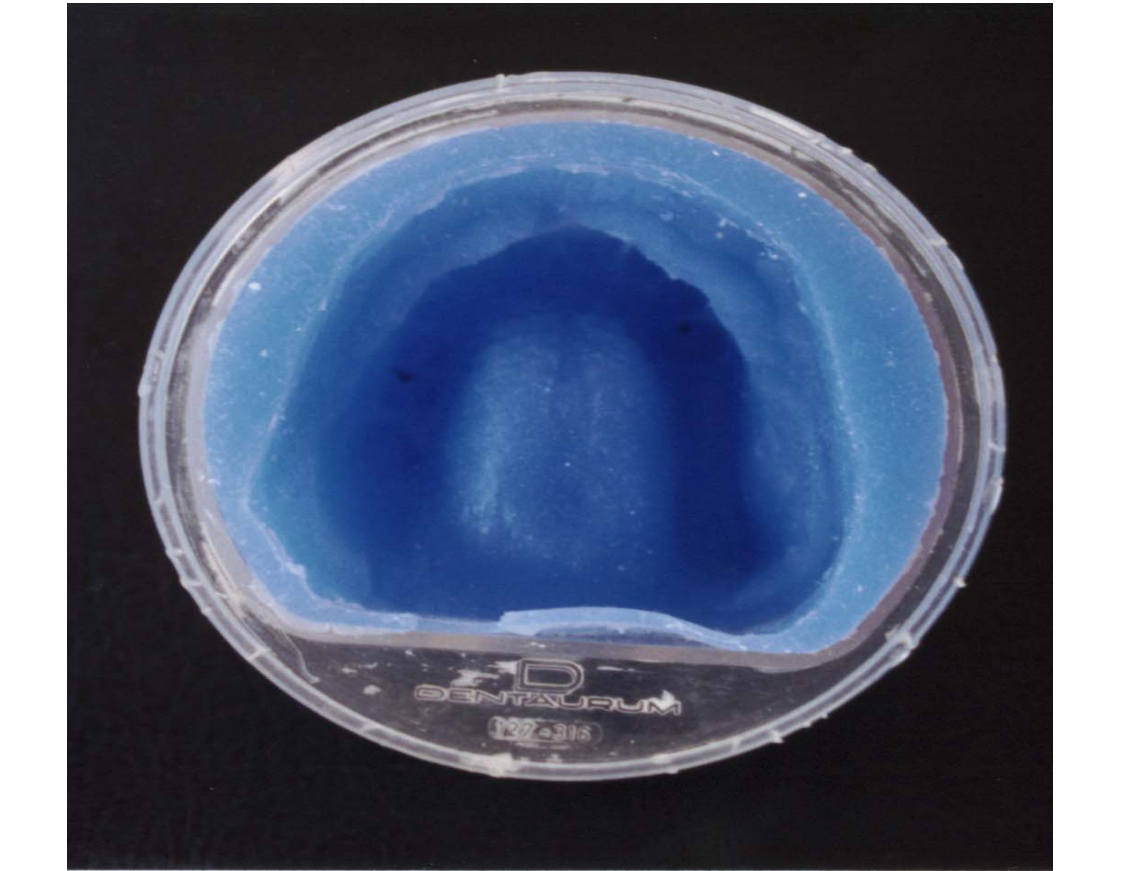
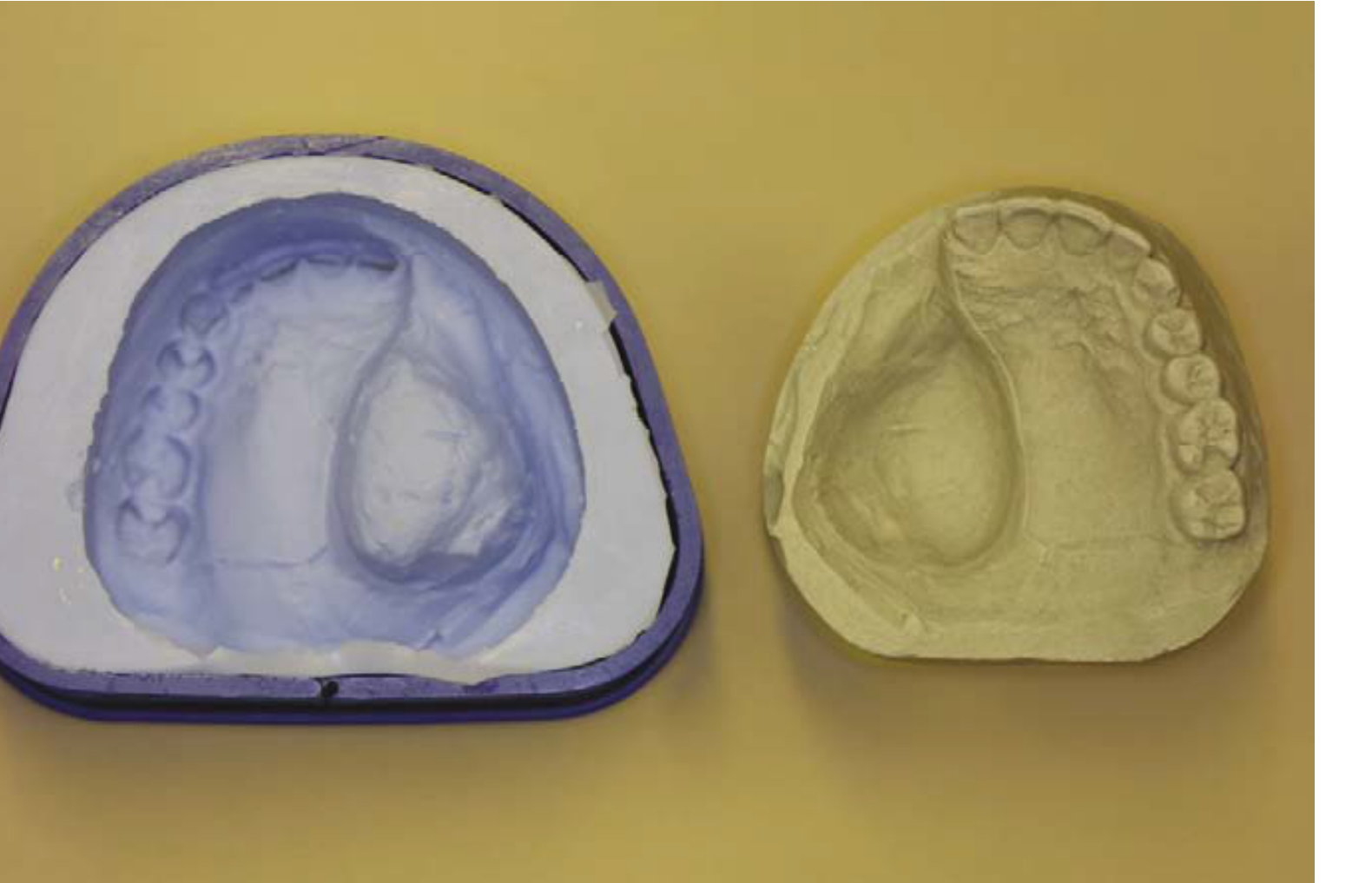
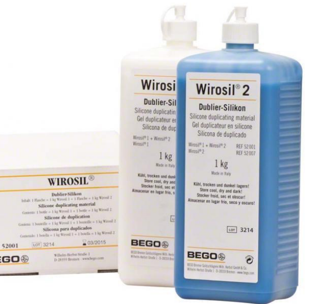
Duplication of Master Model12
Following the completion of the block out of undercuts and the application of necessary reliefs, the master model must be duplicated.
- Block Out: All areas below the height of contour are blocked out with wax, except the portion of the tooth engaging the retention arm.
- Relief (Mesh): Cannot be in close contact with soft tissue; place wax over edentulous area leaving a window for tissue stops.
- Relief (Connector): Wax is added underneath for the mandible; for the maxilla, there is no relief as the hard palate supports the denture.
Investment Model Creation
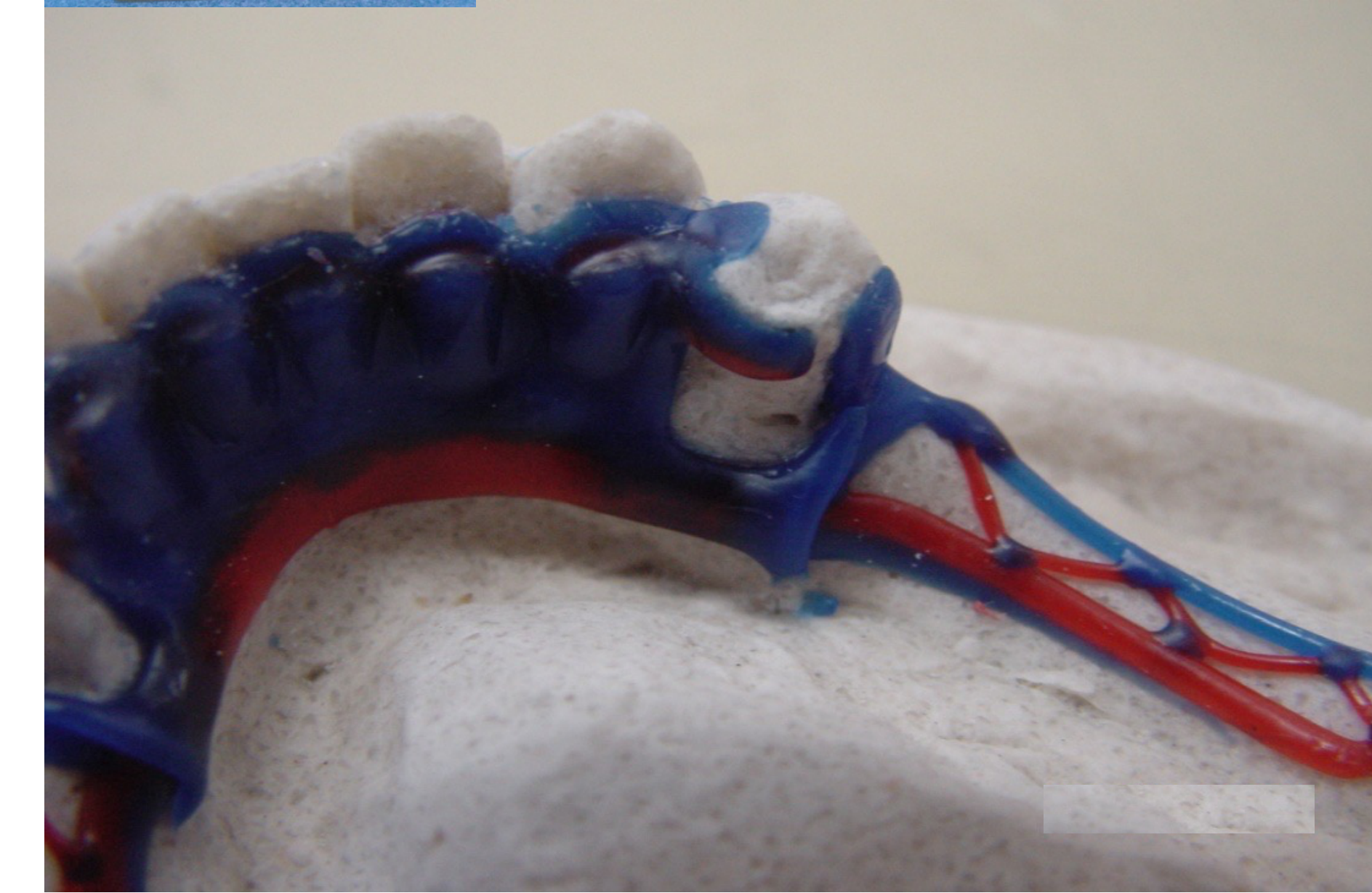
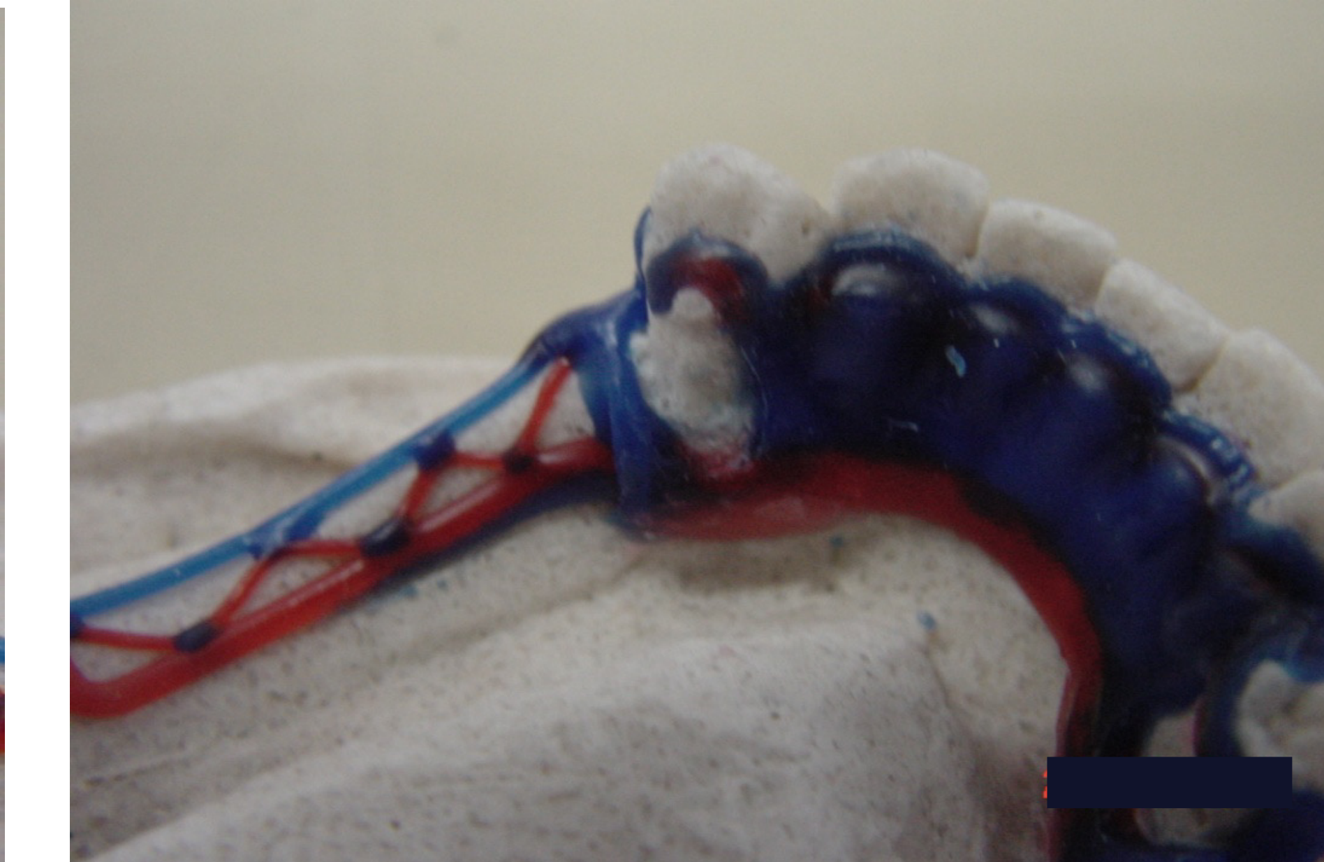
- The duplication process results in an investment model (refractory cast).
- This investment model is used specifically for the framework fabrication process.
- Fabrication: The lab waxes up the framework on this model, and the wax is replaced by metal during casting using compatible investment material.
- For a demonstration of the laboratory steps involved, watch the video “Duplicating”.
Framework Fabrication
Preparation for Casting13
The fabrication process involves several critical technical stages to ensure the precision of the metal framework:
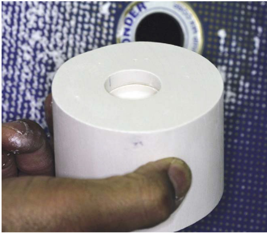
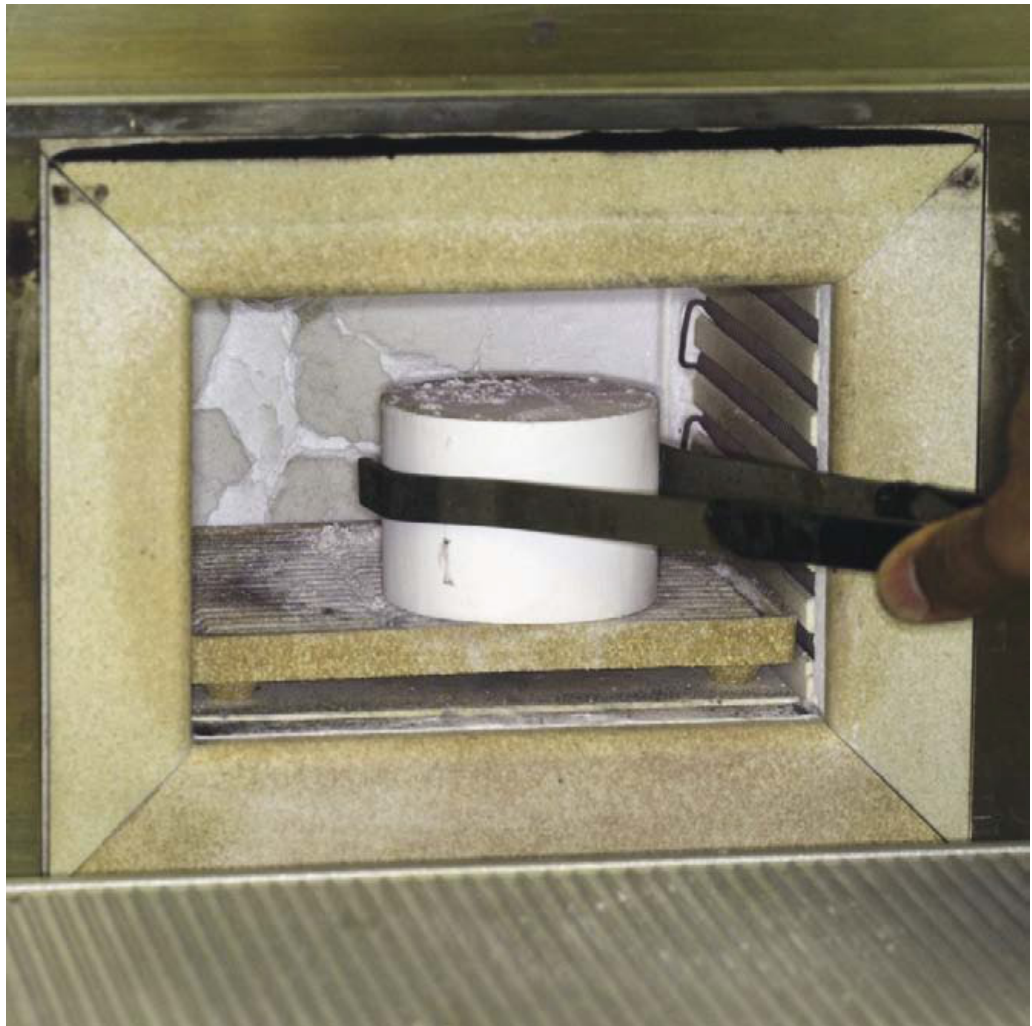
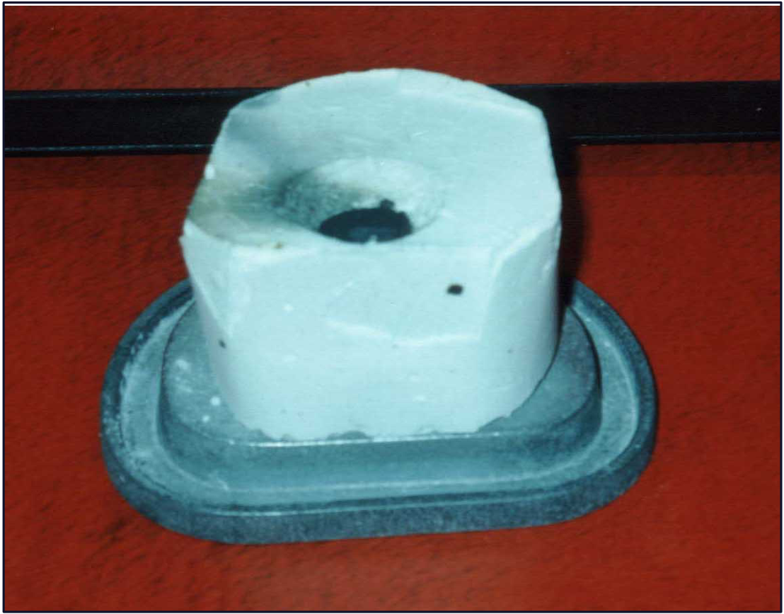
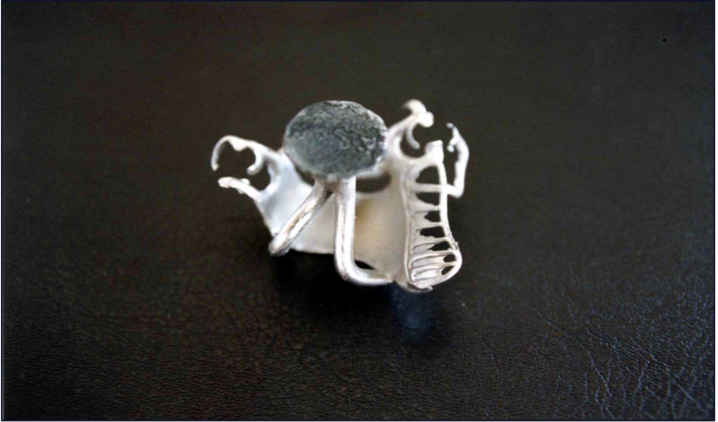
Casting of RPD Framework14
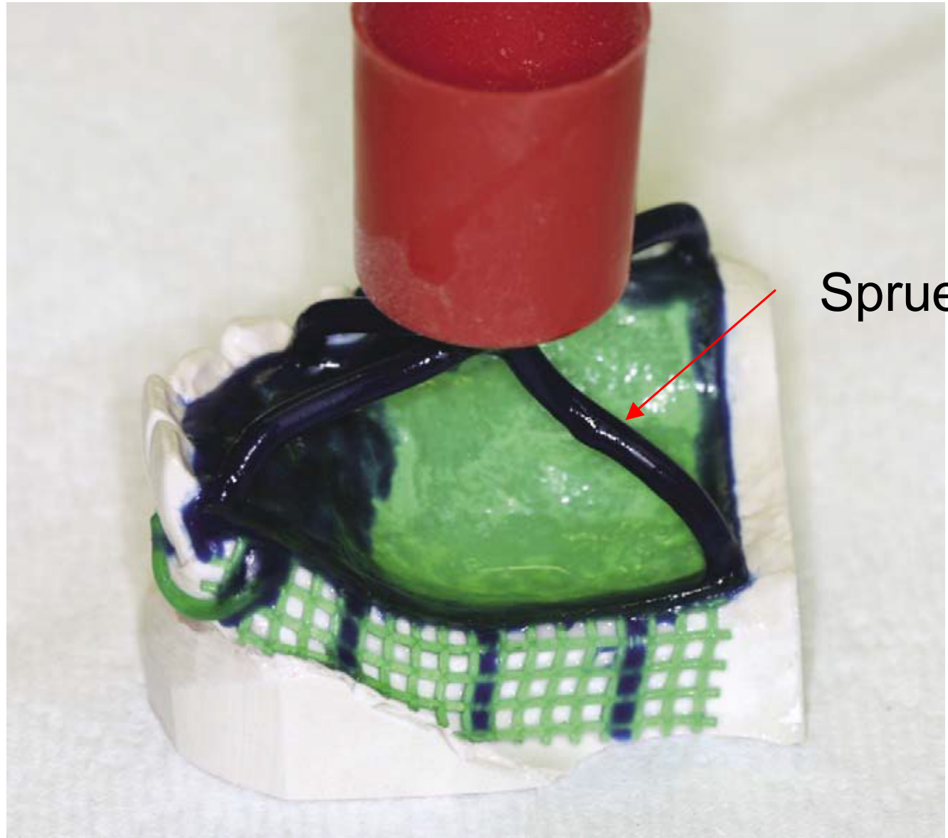
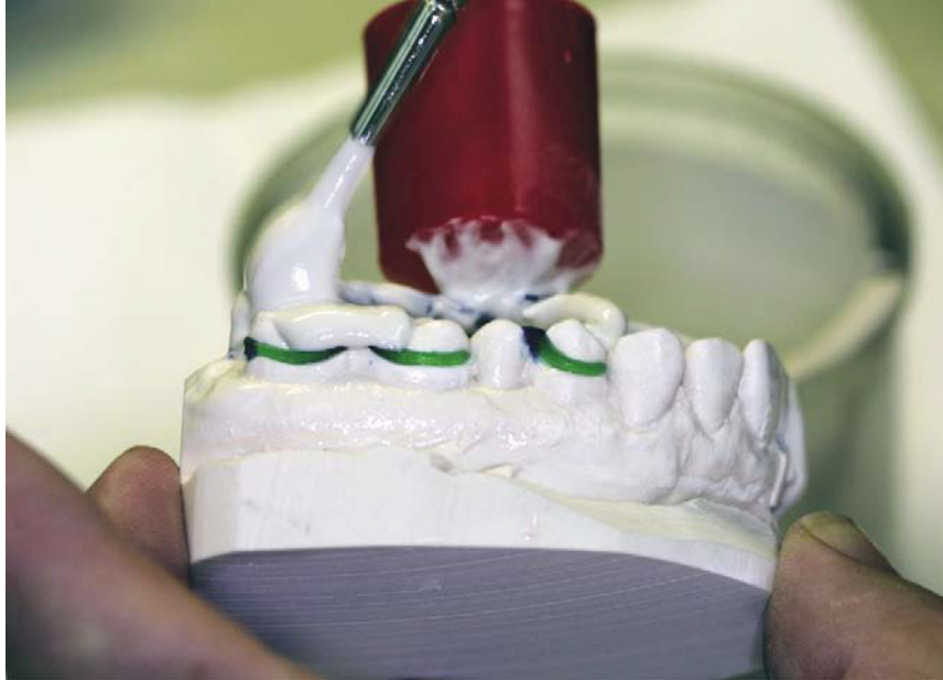
- Spruing: The process of creating channels for the molten metal to enter the mold cavity.
- Burnout technique: The controlled heating of the investment mold to eliminate the wax pattern and prepare the mold for the metal alloy.
- After casting, the framework is finished and polished.
Clinical and Laboratory Sequence15
The following steps outline the progression from the master cast to the finished metal framework:
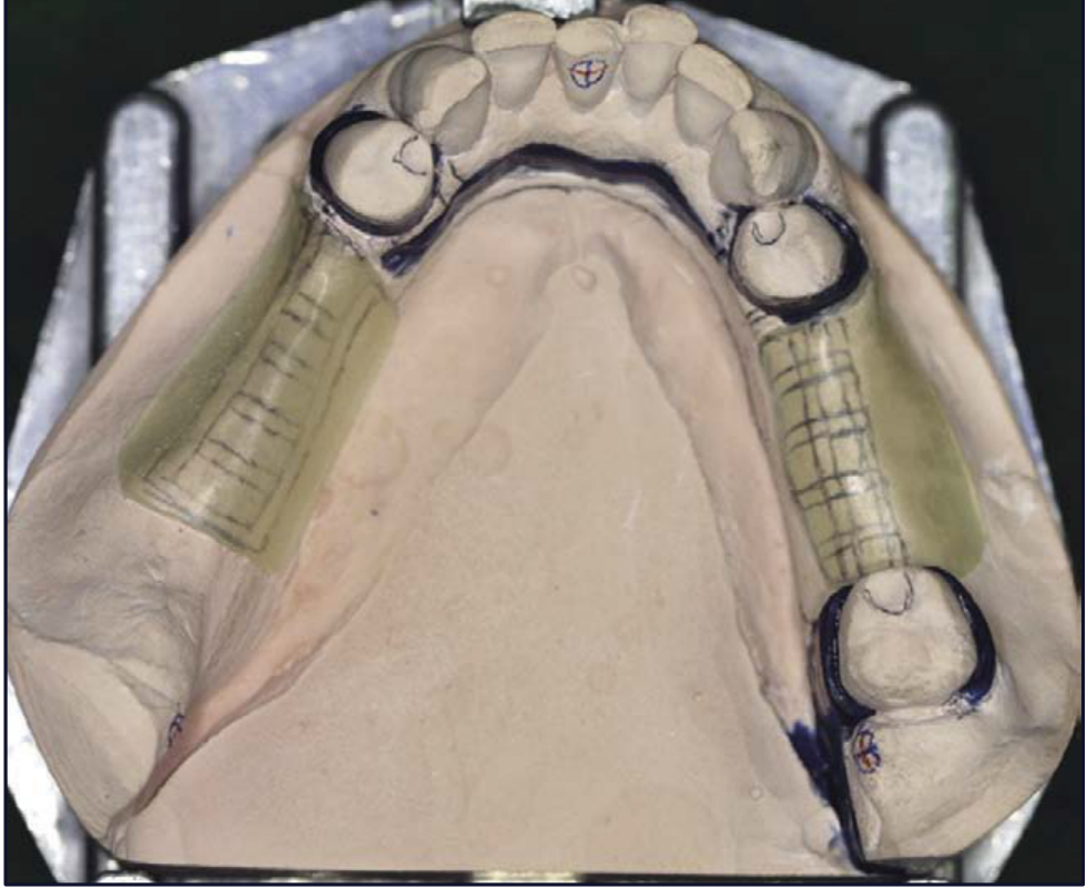
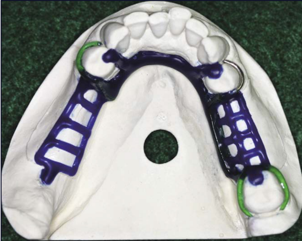
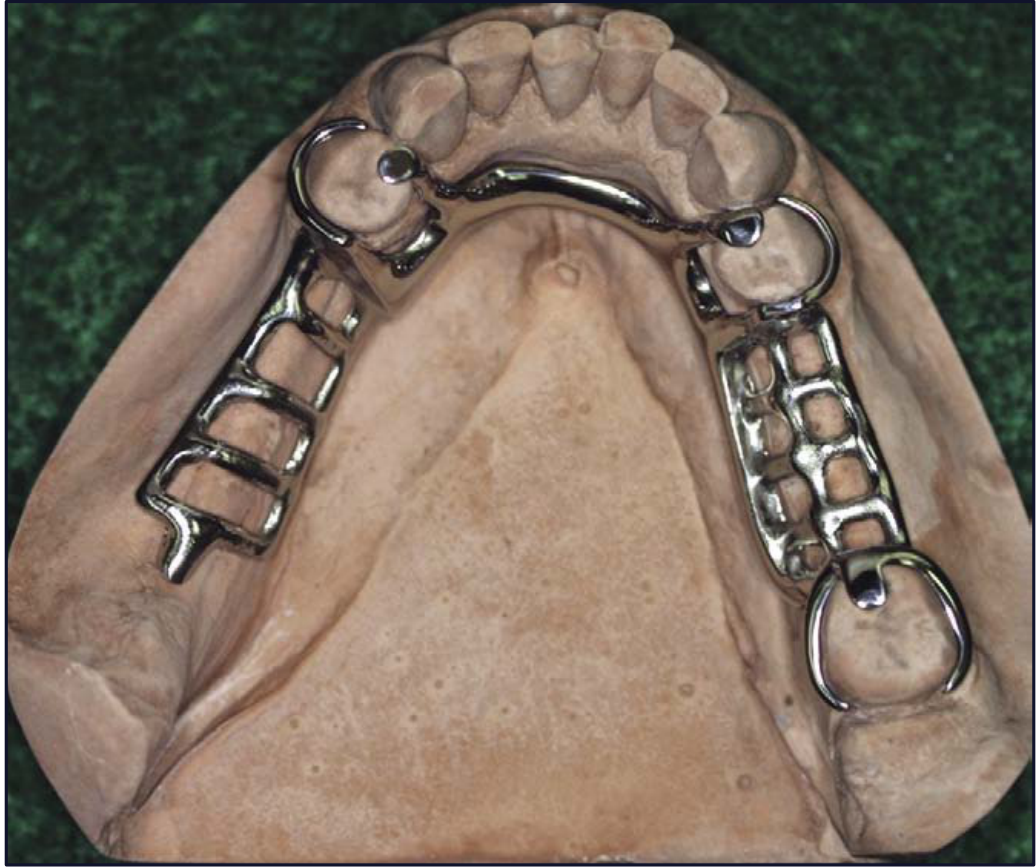
- Blockout of the master cast: Eliminating undercuts on the master cast to ensure the framework can be seated and removed without interference.
- Wax pattern on investment model: The framework design is meticulously waxed onto a refractory (investment) cast duplicated from the master cast.
- Cast framework on the duplicated master cast: The final metal casting is fitted and finished on the duplicated master cast to verify accuracy and fit before clinical try-in.
Model Distinction
Fit check is performed on the duplicated master model, which is different from the original model that was blocked out.
Framework Try-In and Adjustment
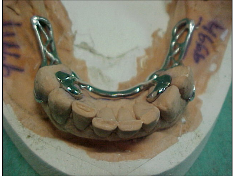
Assessment Off the Model
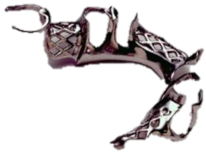
- Check for defects on the tissue side of the framework.
- Check for abraded areas on the master cast.
- Assess the smoothness of the framework.
- Check for adequate thickness.
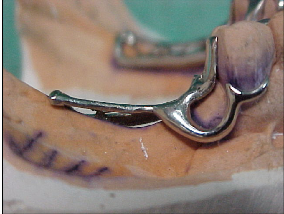
Assessment of Cast Framework
Assessment On the Master Model
- Verify if the framework follows the design that you created.
- Check the seating of the framework on the master model.
- Check for proper adaptation and placement of clasps.
- Check the ease of framework removal.
Assessment Off the Model16
- Check for defects on the tissue side of the framework.
- Check for abraded areas on the master cast.
- Assess the smoothness of the framework.
- Check for adequate thickness.
- Smoothness: Tissue side, major connector, and tooth contact areas should be smooth but not highly polished to avoid affecting retention.
- Mesh: Should be finished but not highly polished to ensure strong engagement of the acrylic base.
- Thickness: Verify adequate thickness of the major connector, minor connector, rest seats, and clasp arms.
Assessment On the Master Model
- Verify if the framework follows the design that you created.
- Check the seating of the framework on the master model.
- Check for proper adaptation and placement of clasps.
- Check the ease of framework removal.
- Note: Retention on the cast differs from the mouth due to surface roughness differences.
Assessment In the Mouth
Clinical Evaluation Criteria
- Passive Seating: Ensure the seating of the framework in the mouth is passive.
- Rest Seats: The framework must be fully seated on rest seats with clasps in the correct position.
- Retention and Stability: Evaluate the framework’s resistance to displacement.
- Soft Tissue Relationship: Check the relationship and clearance with the soft tissue.
- Stability: The framework should not rock; pressure on one rest seat should not lift the opposing side.
- Mesh Relief: Assess if there is adequate relief under the mesh for sufficient acrylic.
- Discrepancy: If the framework fits the cast but not the mouth, the cast may be inaccurate.
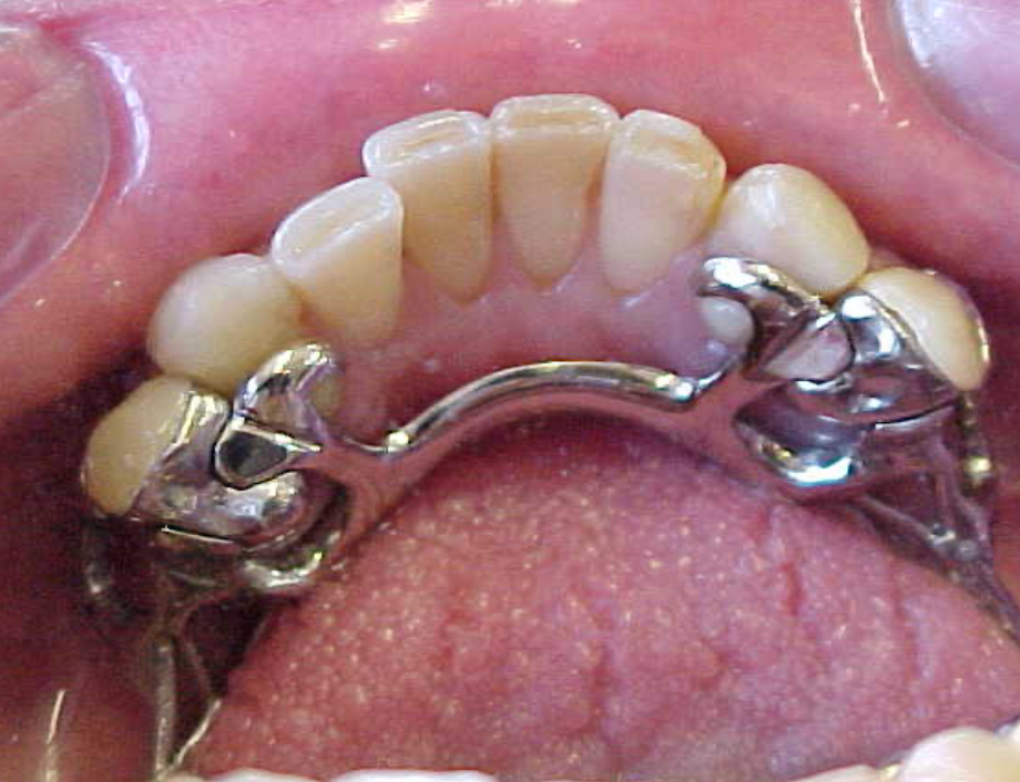
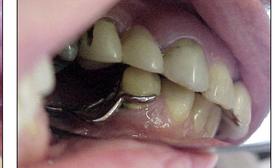
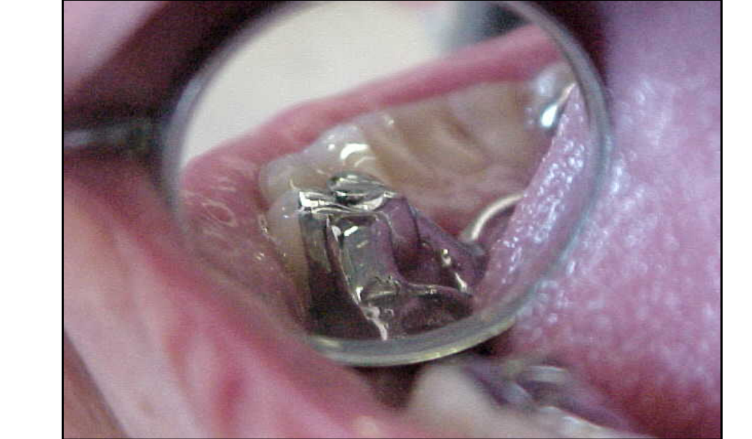
Framework Adjustment17
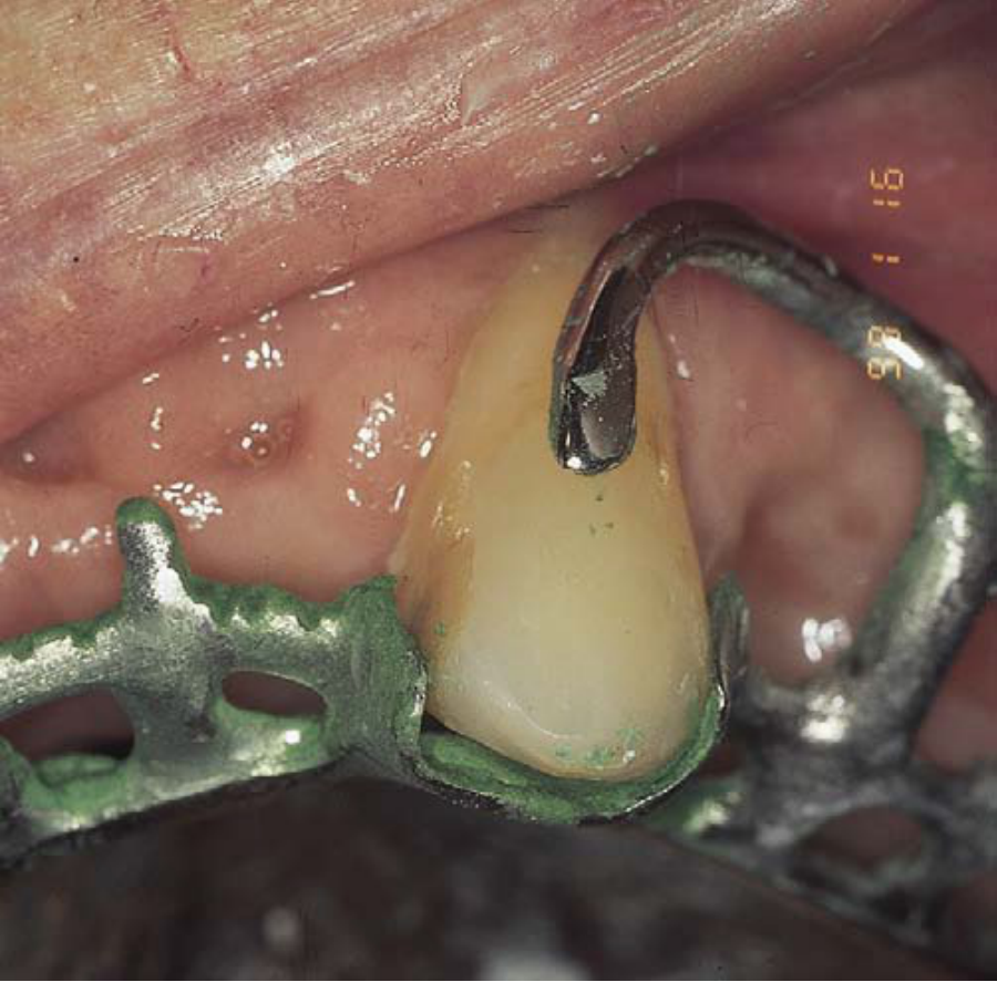
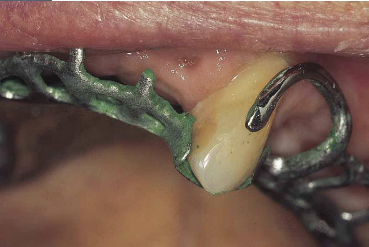
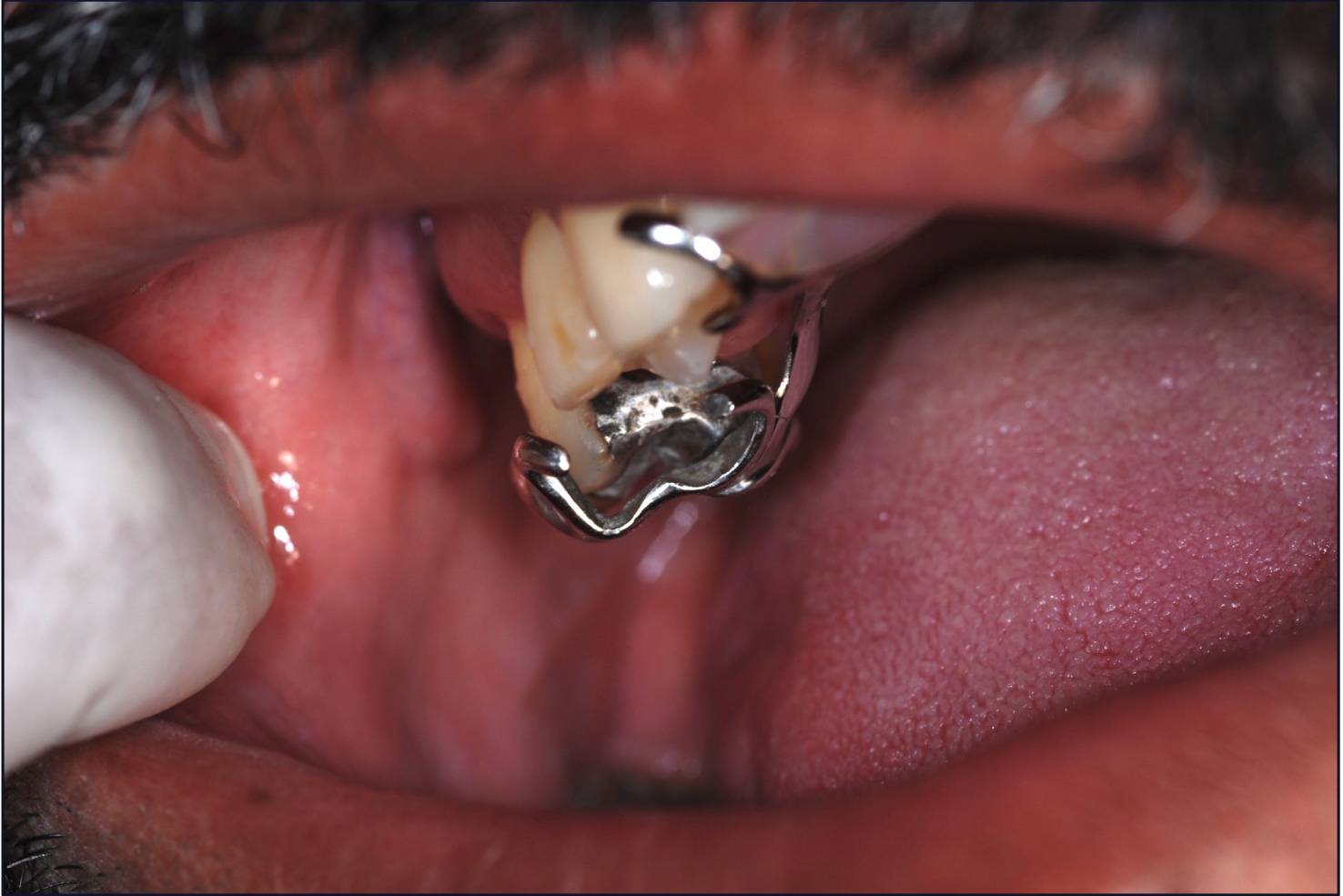
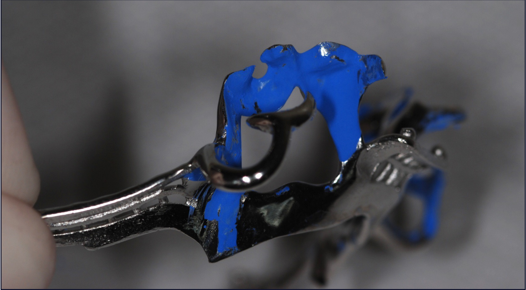
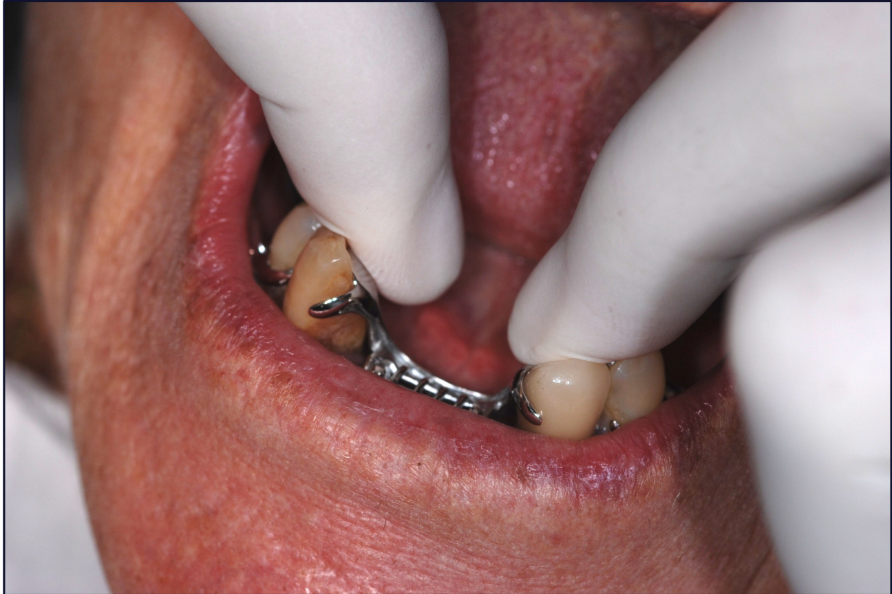
Framework Adjustment Procedures18
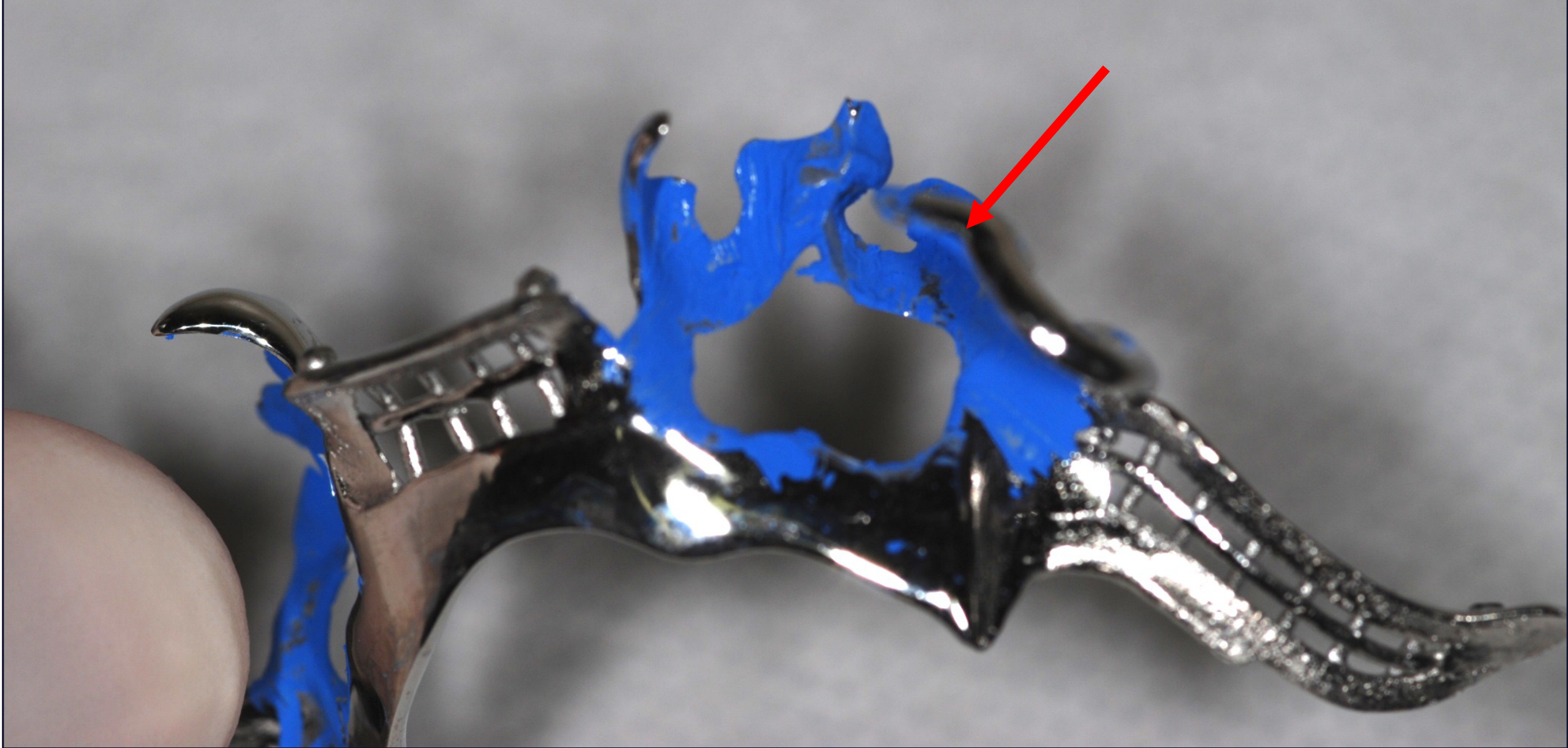
Visual inspection and mechanical adjustment of the metal framework are necessary to ensure proper fit and function. This involves identifying pressure points or interferences that prevent complete seating.
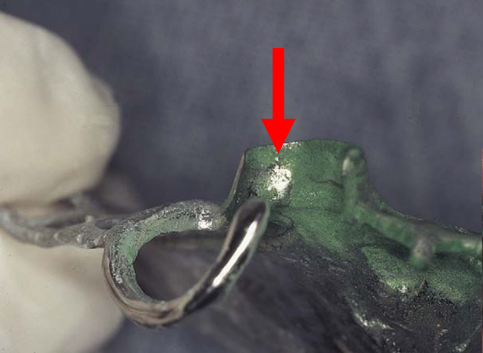
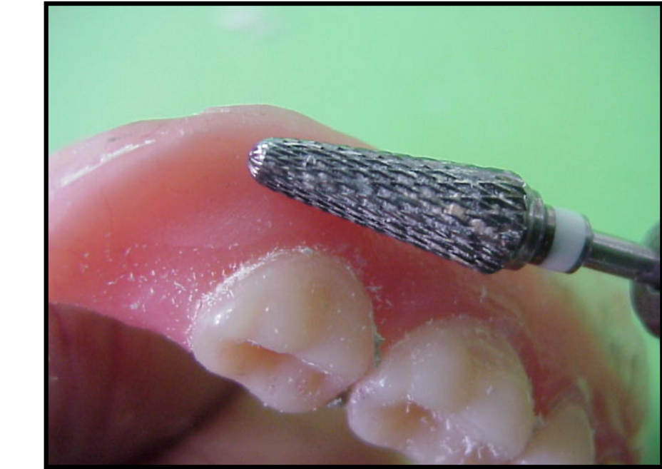
- Disclosure Medium: Use fit checker spray or carbon mark liquid to identify interference points.
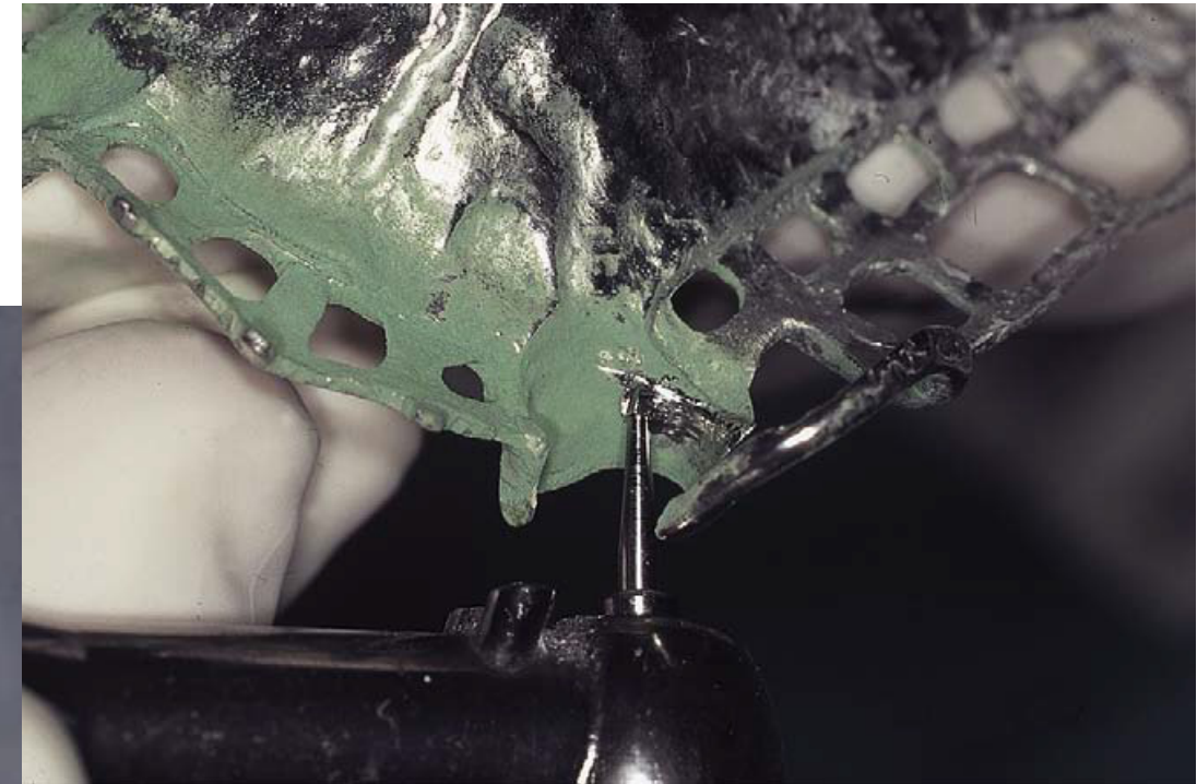
- Method: Apply to internal surface, seat framework, grind areas where medium is removed with a high-speed cylindrical carbide bur.
- Major Interference: If there is major interference or distortion, a new impression and framework are required.
Case Study: Framework Seating Interference
In a scenario where the framework does not sit fully (gap between rest and rest seat):
- Diagnosis: Interference preventing seating.
- Adjustment: Grind the identified interference points with a carbide bur.
- Critical Rule: Do not touch the terminal third of the retention arm with the bur.
Case Study: Carbon Mark Liquid Adjustment
Similar to fit checker spray, carbon mark liquid identifies high spots.
- Assessment: The first point of assessment is always the rest.
Visual inspection and mechanical adjustment of the metal framework are necessary to ensure proper fit and function. This involves identifying pressure points or interferences that prevent complete seating.
Adjustment Sites on Framework
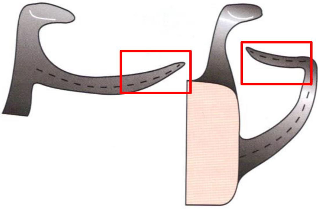
Permissible Adjustment Areas
Adjustments can be made to the following components:
- Minor connectors
- Reciprocating arm
- The proximal 2/3 of the Retentive arm
Contraindications
- Never adjust the final 1/3 (the terminal tip) of the Retentive arm.
Occlusion Interferences
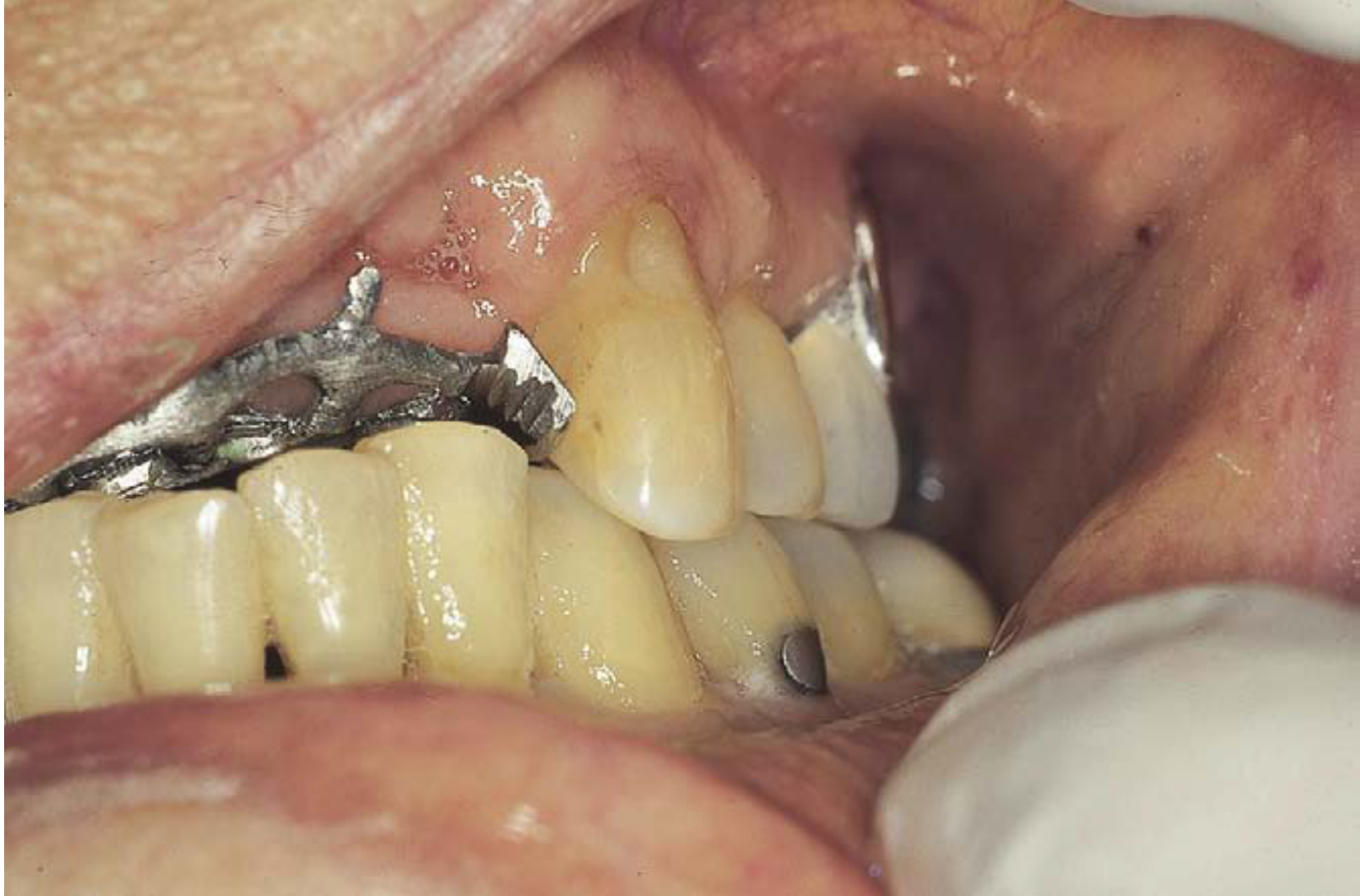
- Evaluate the framework for any occlusal interferences with the opposing dentition.
- Ensure the framework does not prevent the patient from reaching maximum intercuspation or interfere with lateral excursions.
- Assessment: Assess occlusion with the framework in position using shim stock and articulating paper.
- Planning: Proper planning on study models should avoid major interferences.
Maxillo-Mandibular Relationship and Processing
To facilitate the mounting of the master model, the following steps are required for Kennedy Class I, II, and extensive Class IV cases:
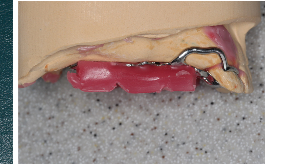
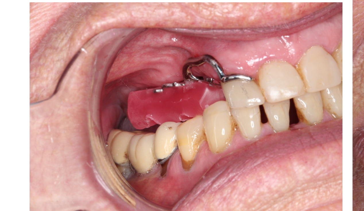
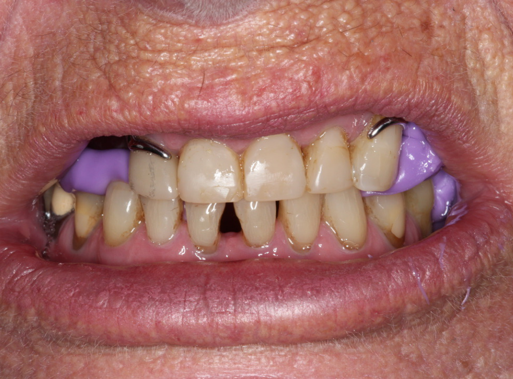
Maxillo-Mandibular Relationship Recording19
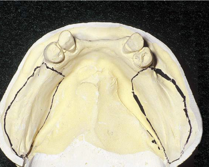
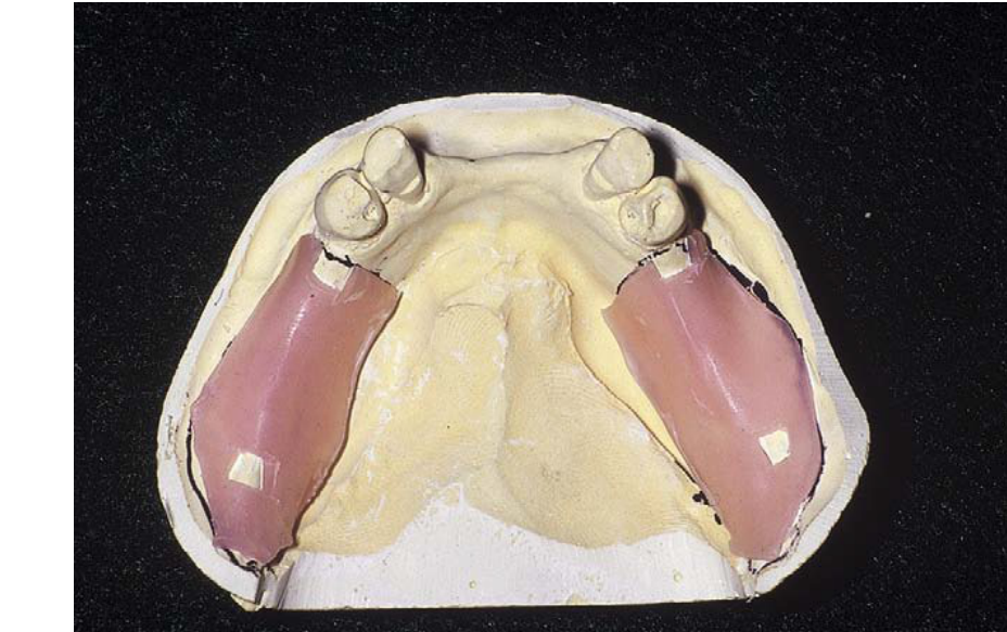
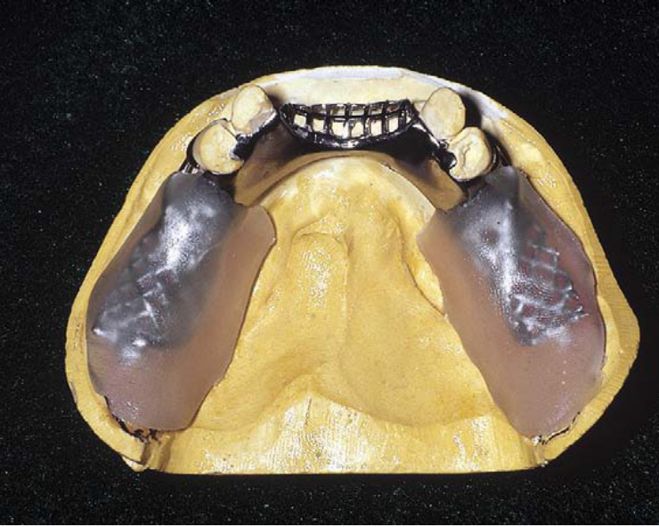
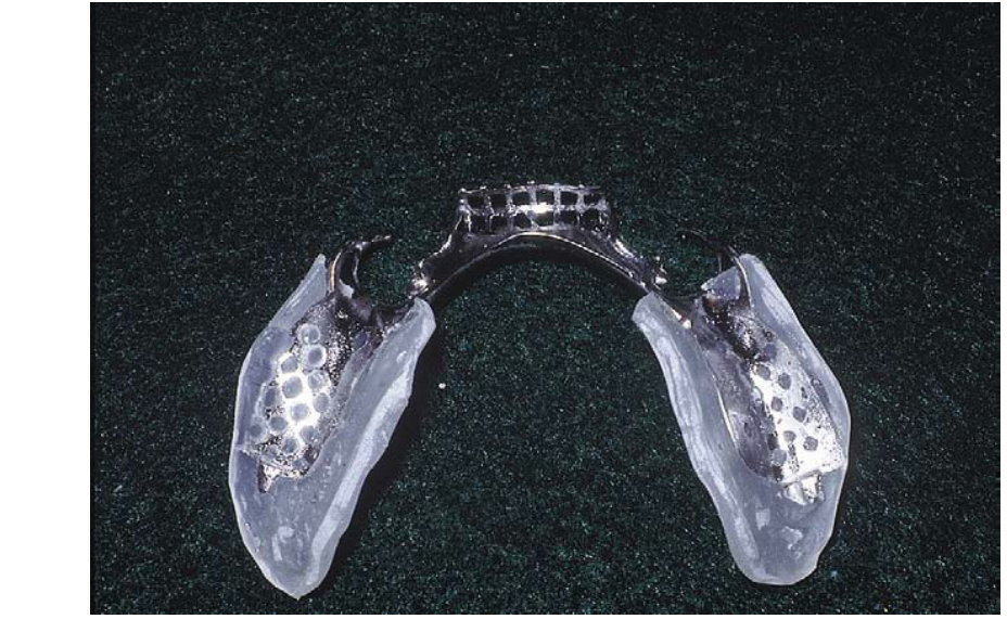
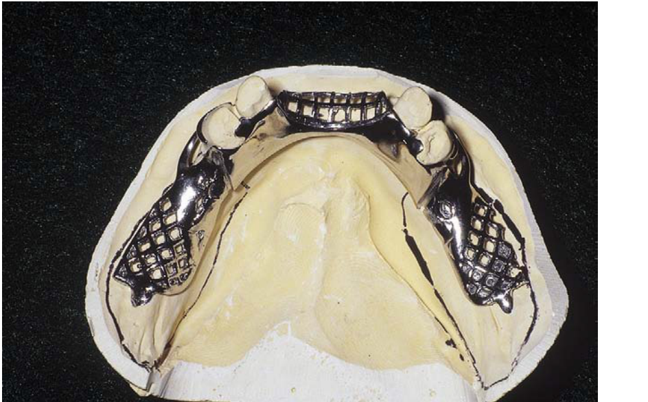
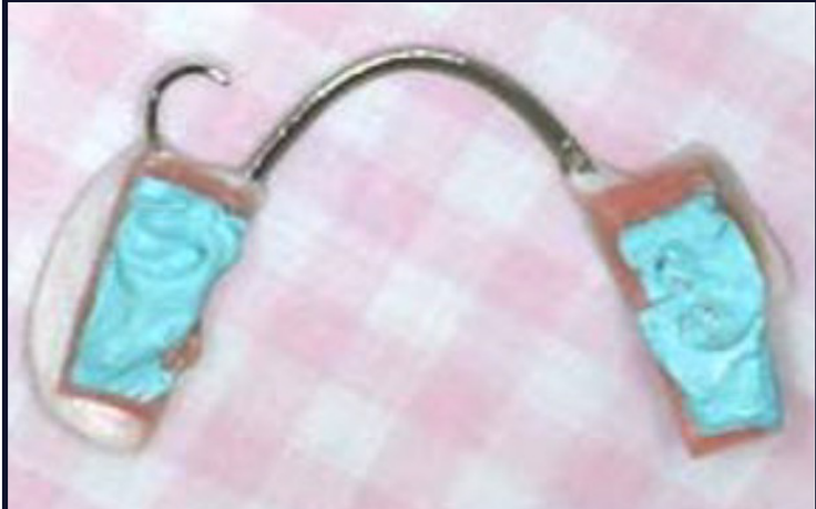
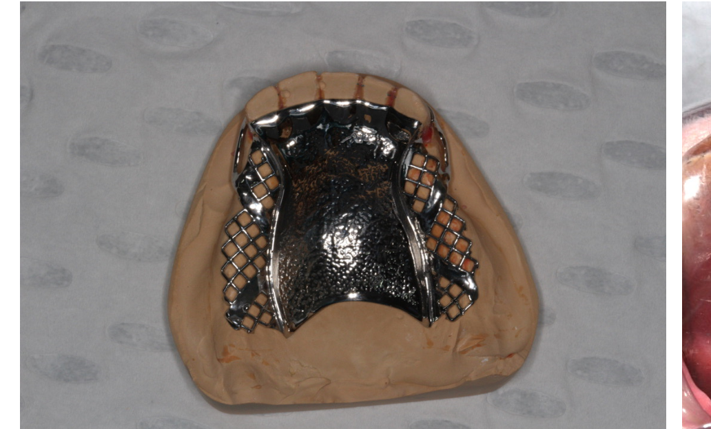
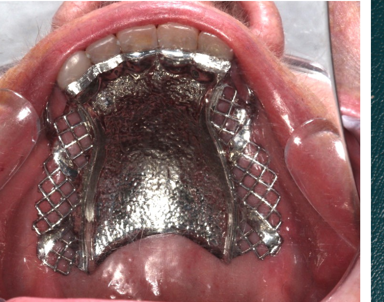
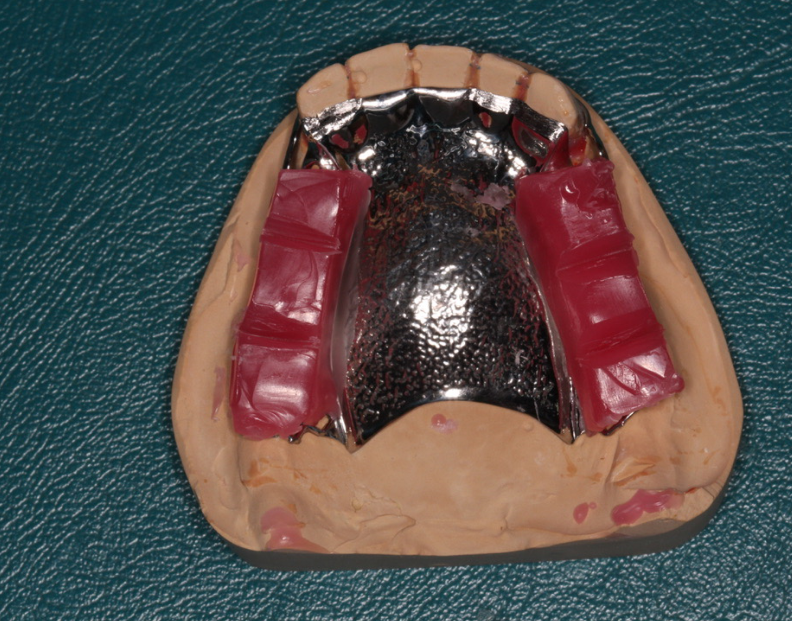
- Add an acrylic base to the saddle region of the framework.
- Ensure the acrylic base is securely connected to the framework to provide stability during the recording of the maxillo-mandibular relationship.
- Class 3 cases: Models may be hand-related with normal bite registration material.
- Base Plate: Must be fabricated within the limits of the bearing area to avoid impinging soft tissue.
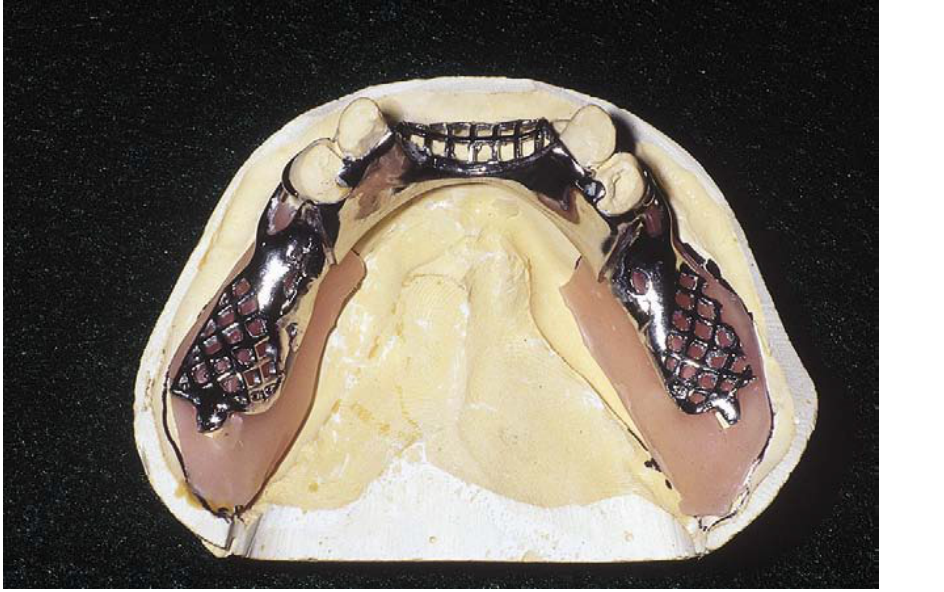
Acrylic Base Addition and Framework Connection2021
For the mounting of the master model in Kennedy Class I, II, and extensive Class IV cases, the following is required:
- Establishment of the maxillo-mandibular relationship.
- Integration of the framework with the acrylic base to ensure accurate recording.
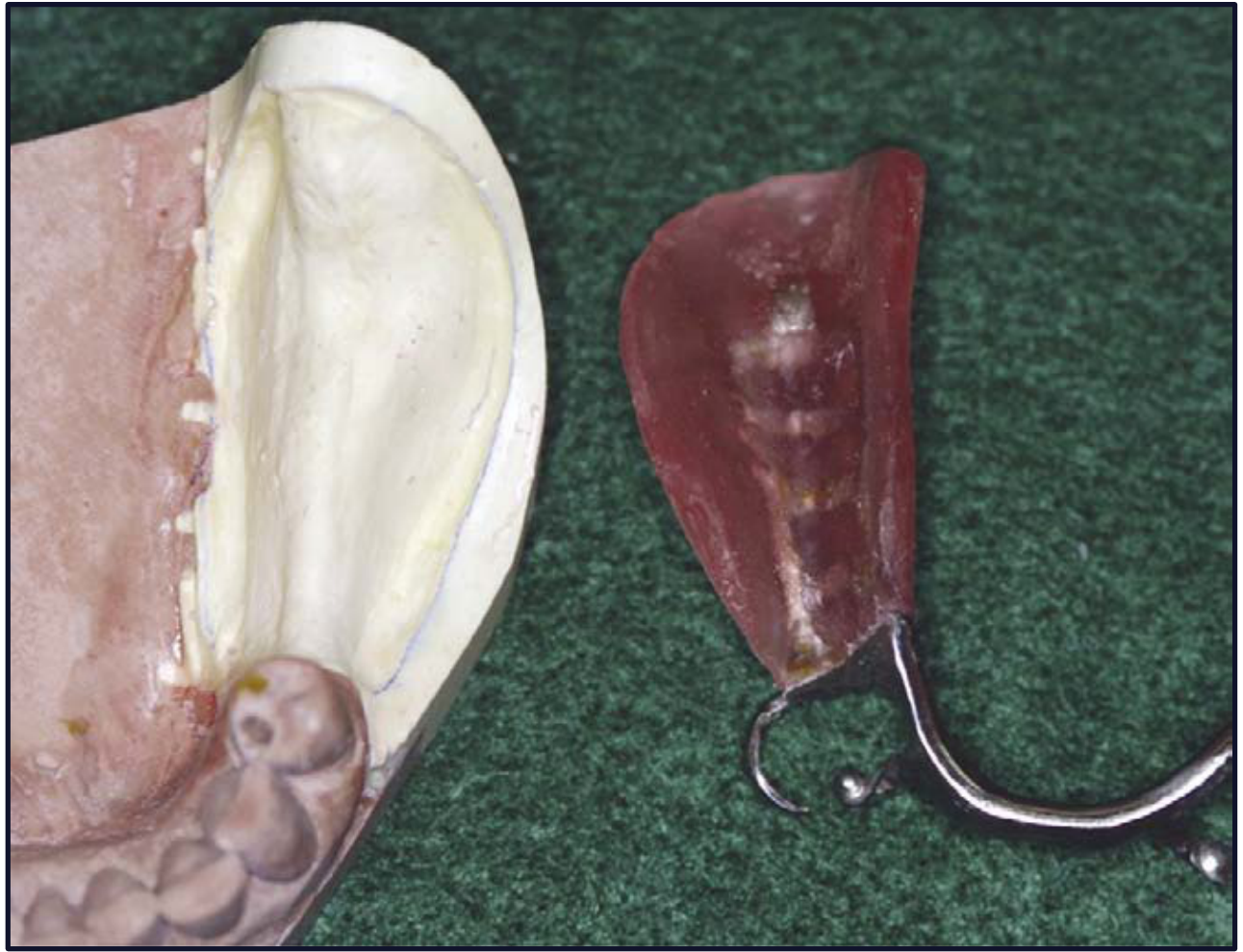
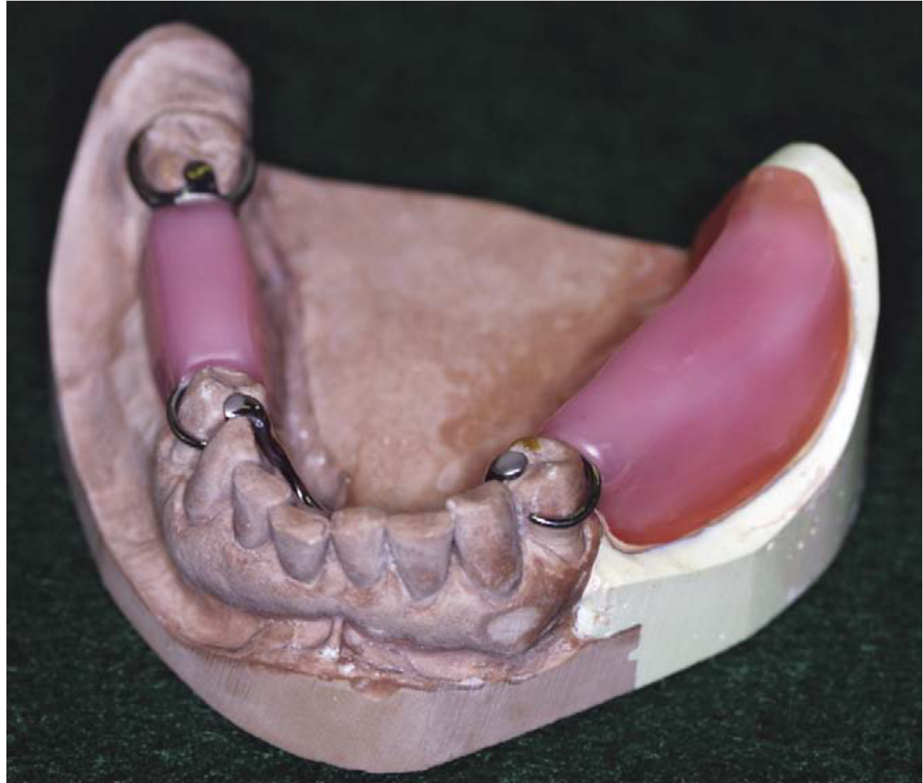
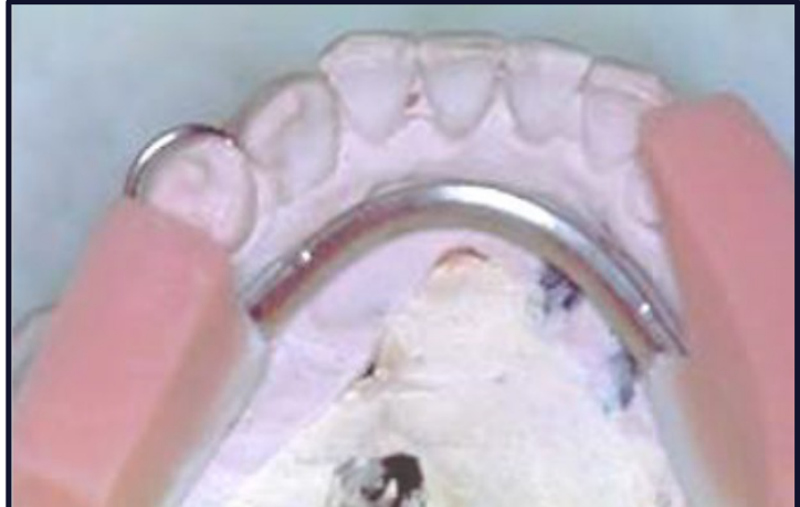

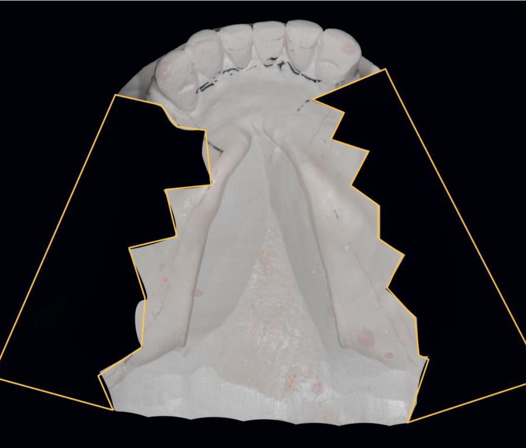
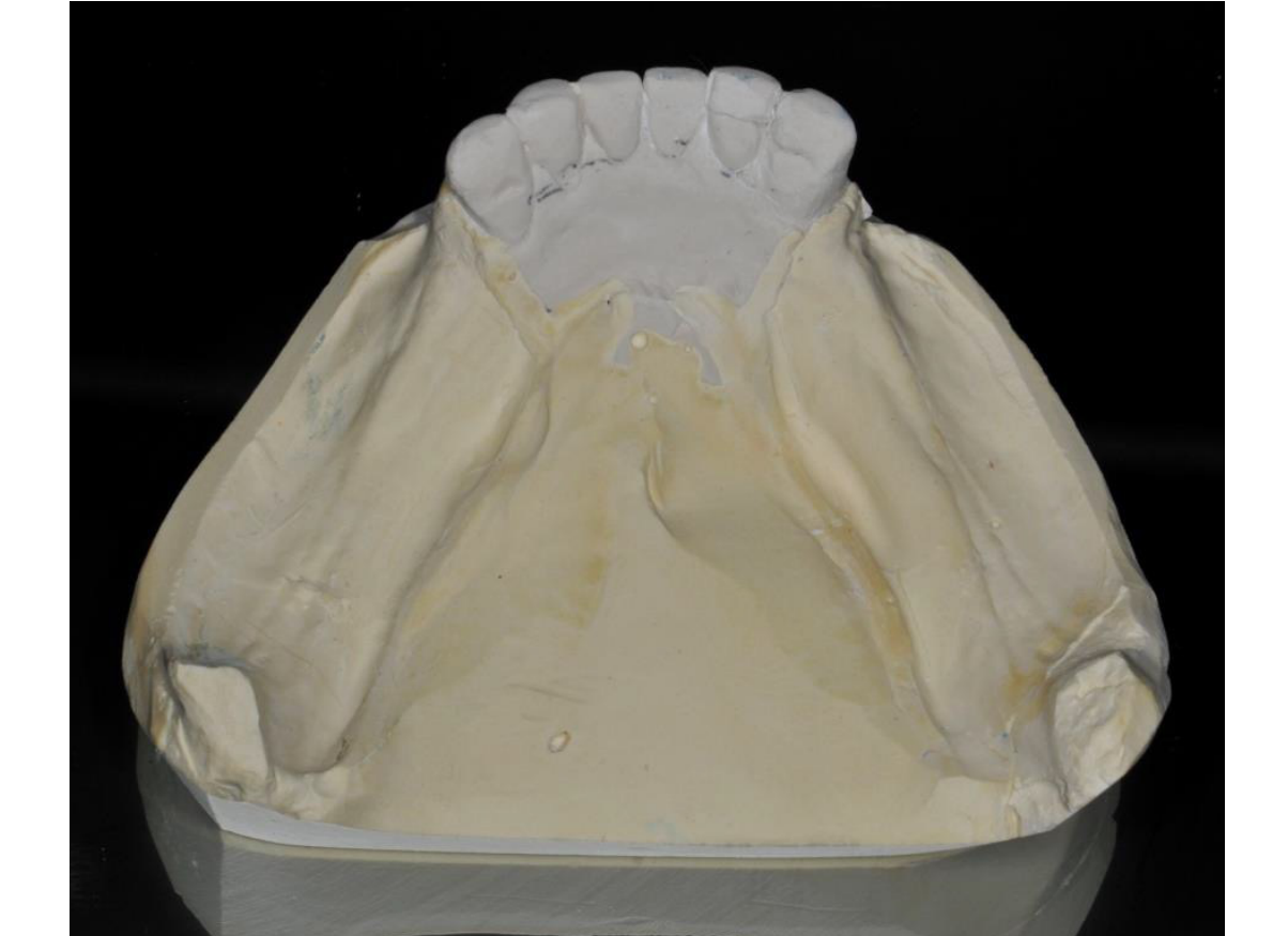
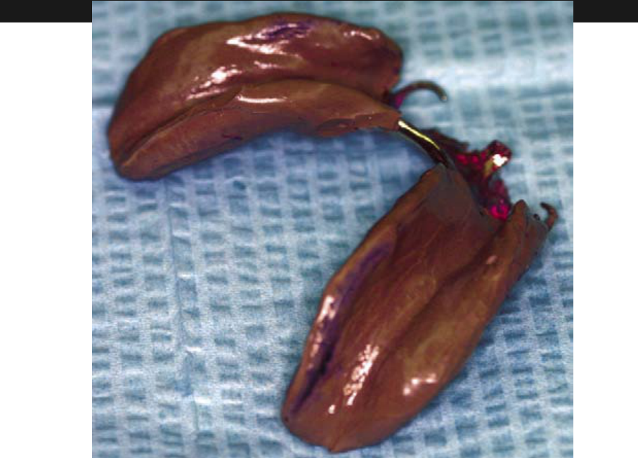
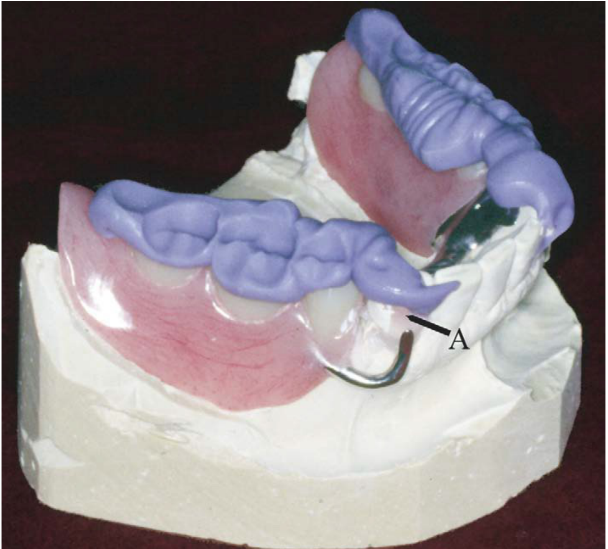
Altered Cast Technique
The altered cast technique is specifically indicated for Mandibular Kennedy Class I and Class II cases to improve the support and stability of the distal extension base.
Altered Cast Process & Contraindications
- Not indicated for maxilla (hard palate supports free-end saddle) or Class 3 cases.
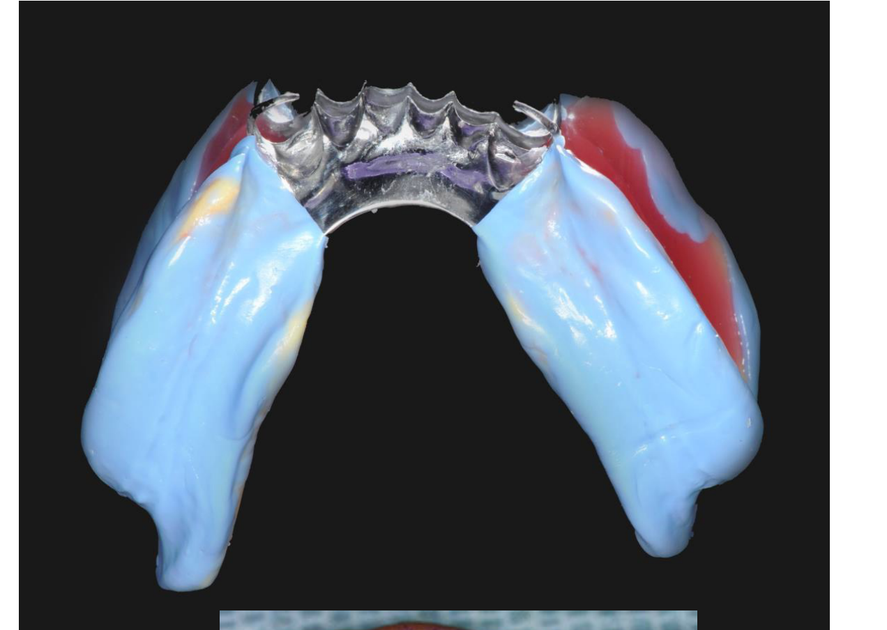
- Purpose: Record edentulous ridge in functional form under controlled compression.
- Process: Return framework to cast, create base plate, add wax rim, border mold free-end saddle, trim model, pour new stone.
Clinical Components
- Integration of the metal framework with the Maxillo-Mandibular Relationship (MMR) records.
- Utilization of wax rims connected to the framework for accurate registration.
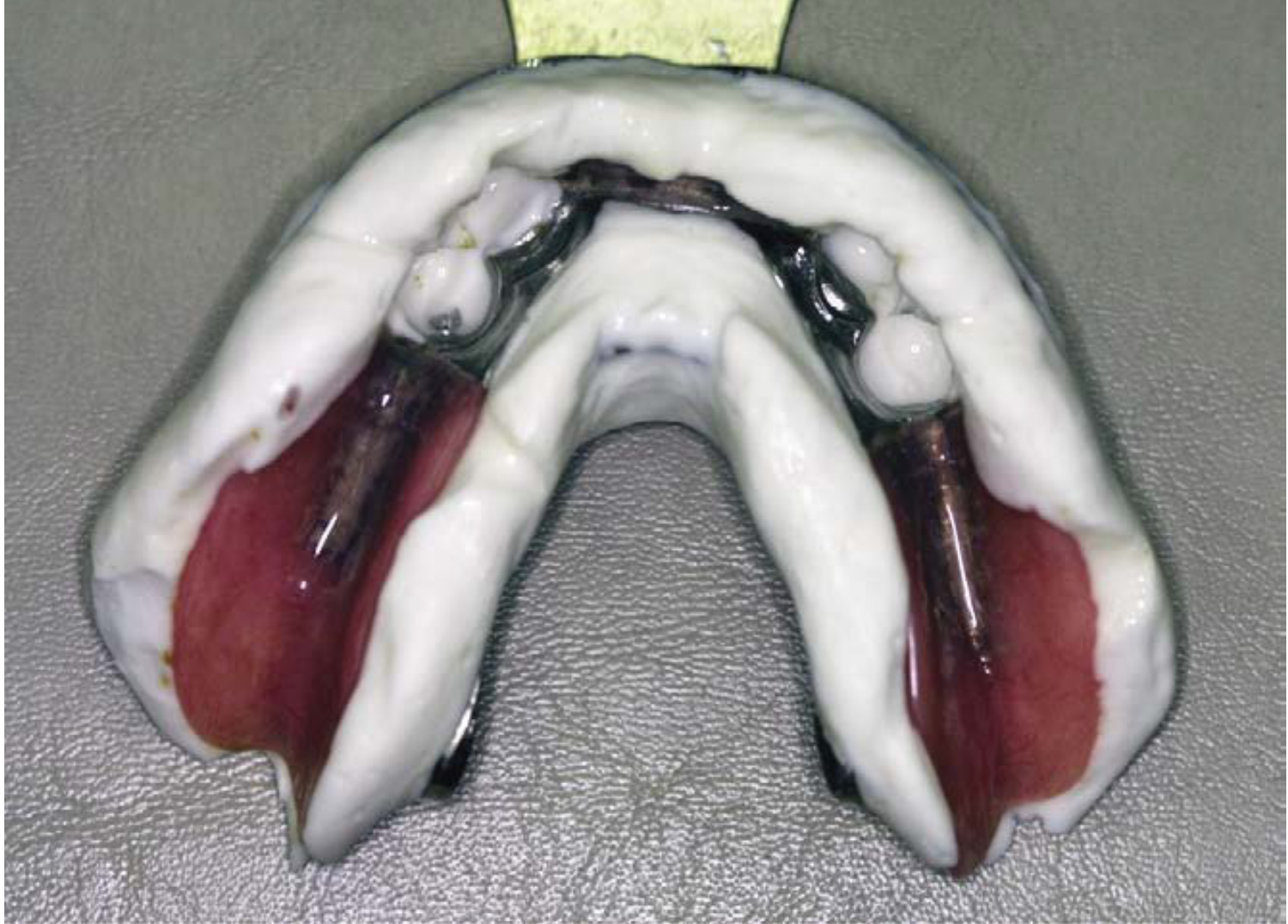
Impression Technique for Altered Cast
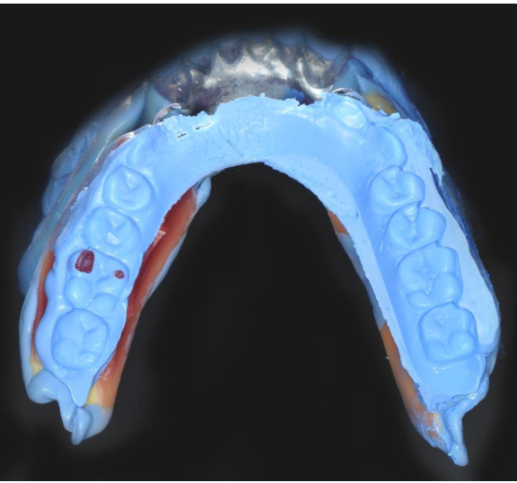
Impression Procedure
- Use putty for border molding to define the peripheral extensions.
- Utilize light body material to accurately capture the details of the free-end saddle ridge.
Clinical Maneuvers and Stabilization
- Finger Pressure: Apply pressure only to the rests of the framework. Never apply pressure to the free-end saddle area (tray) during the impression process.
- Soft Tissue Functional Recording: Instruct the patient to perform tongue movements and retract the cheeks to capture the soft tissues in function.
- Framework Stability: Maintain constant finger pressure on the rests to avoid dislodgement of the framework until the impression material has completely set.
- Timing: The wax rim on the base plate allows bite registration to be recorded immediately after the altered cast impression.
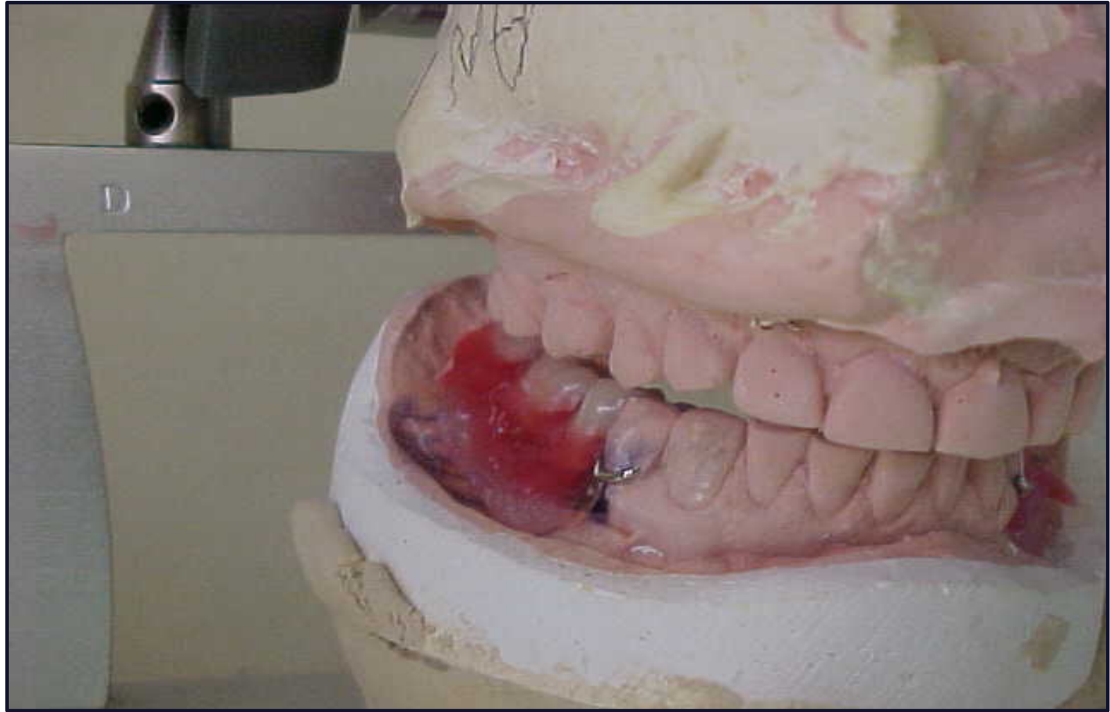
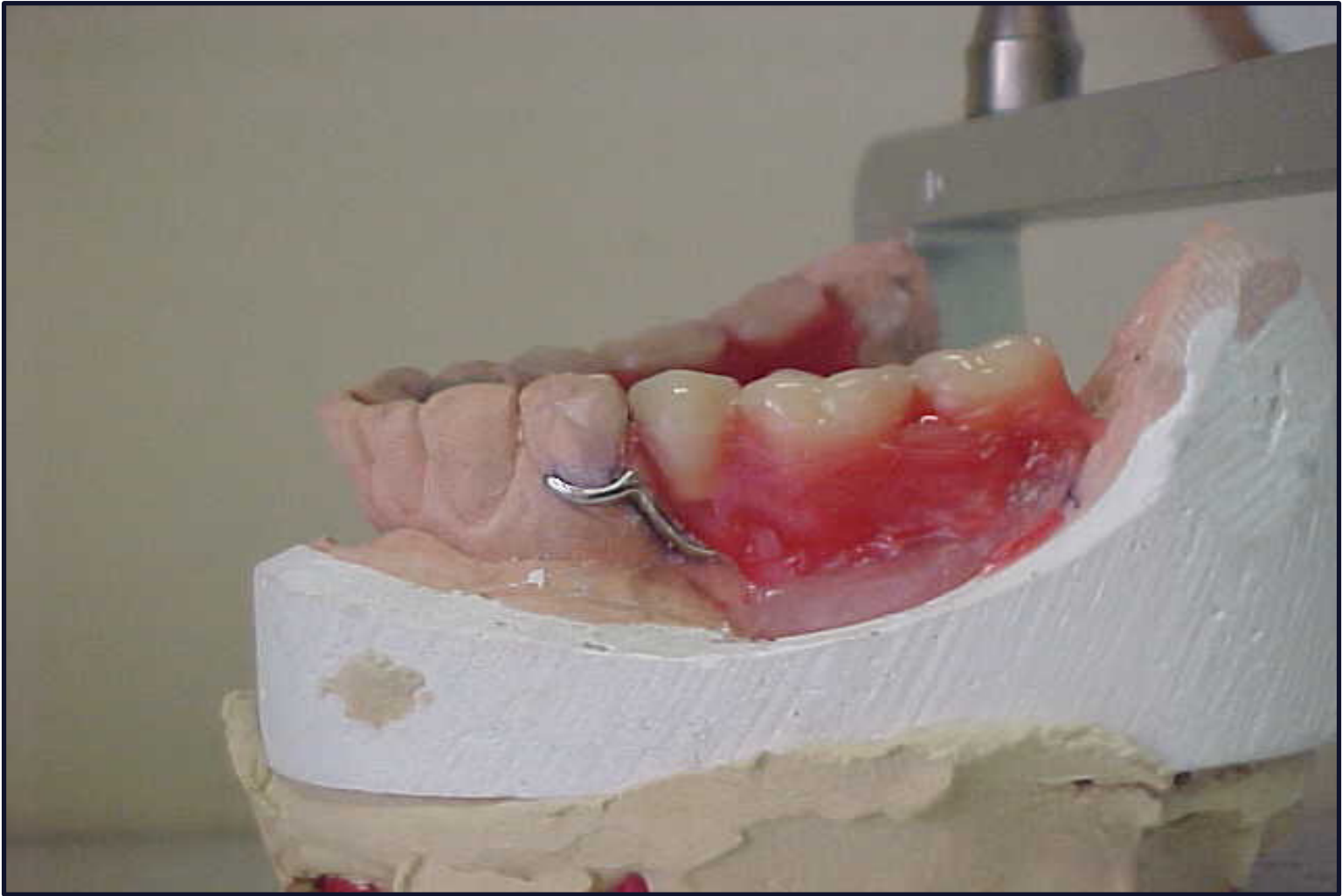
Tooth Arrangement and Waxing22
Following the recording of the maxillo-mandibular relationship, the laboratory phase involves:
- Arranging the artificial teeth according to the established records.
- Waxing the denture base to the desired anatomical contours.
Try-In Evaluation23
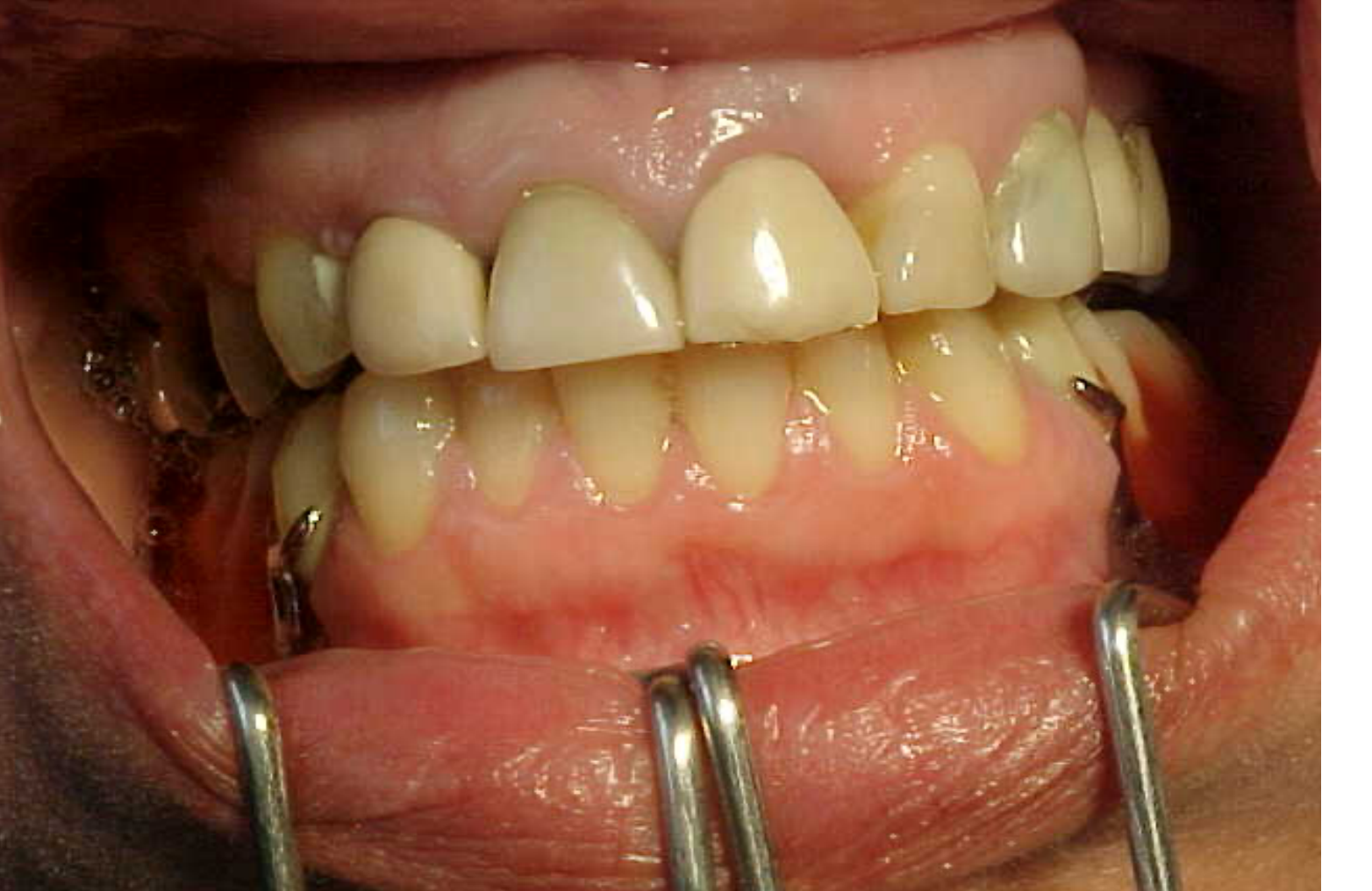
During the try-in stage, the following clinical parameters must be evaluated:
- Occlusal Contacts: Ensure evenness of contact across the arch.
- Vertical Dimension: Verify the established occlusal vertical dimension (OVD).
- Esthetics: Evaluate the overall appearance and tooth position.
- Neutral Zone: Confirm the relationship of the teeth and denture base to the neutral zone.
- Adjustments: It is better to move teeth rather than grind them at this stage.
- Approval: Obtain patient approval before processing.
Neutral Zone Concept
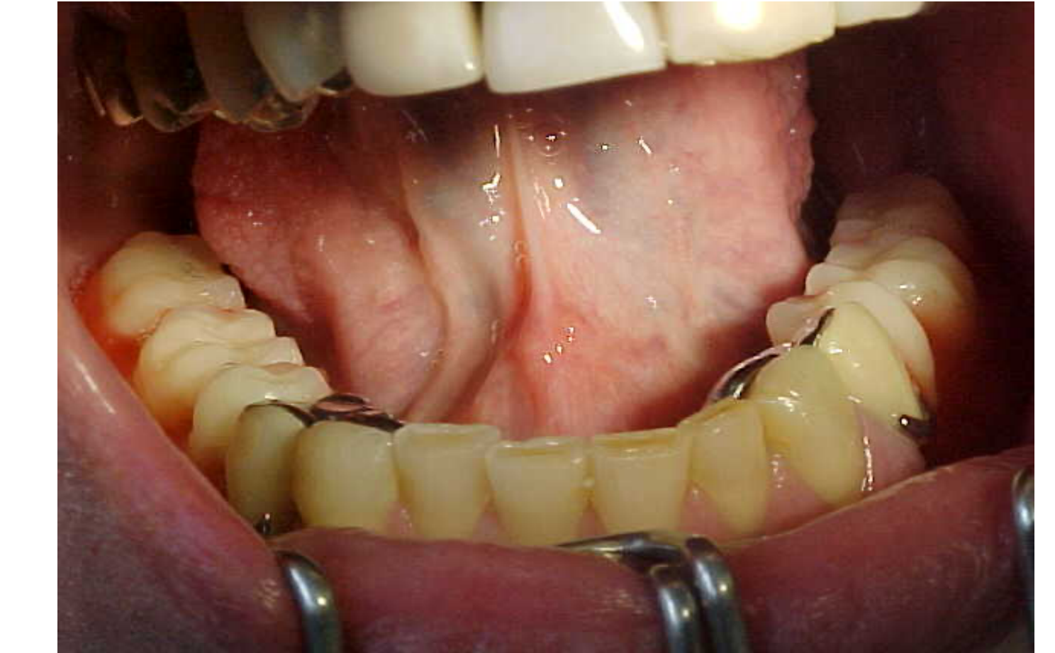
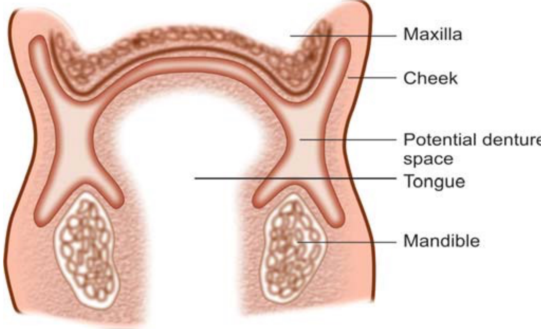
The neutral zone is defined as the potential space where the forces exerted by the tongue are equal and balanced with the forces exerted by the circumoral musculature.
Muscular Boundaries
- Internal Forces: Exerted by the tongue.
- External Forces (Posterior): Exerted by the buccinator muscle.
- External Forces (Anterior): Exerted by the orbicularis oris muscle.
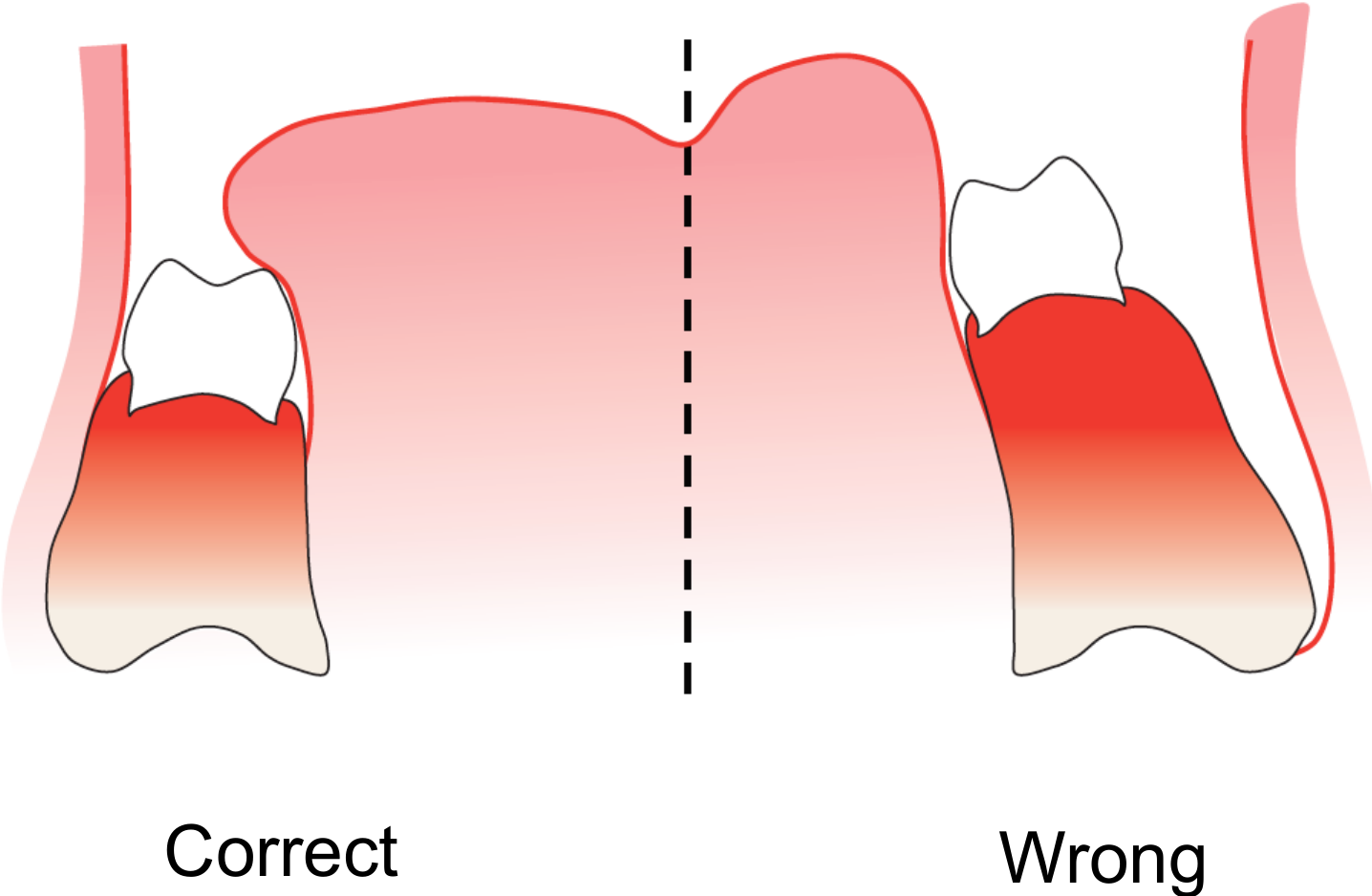
Proper positioning of the denture within this space ensures stability and prevents displacement during function.
- Risk: If teeth are outside the neutral zone, they invade the space of surrounding muscles.
- Consequence: Can cause trauma to soft tissues and instability once the patient wears the denture.
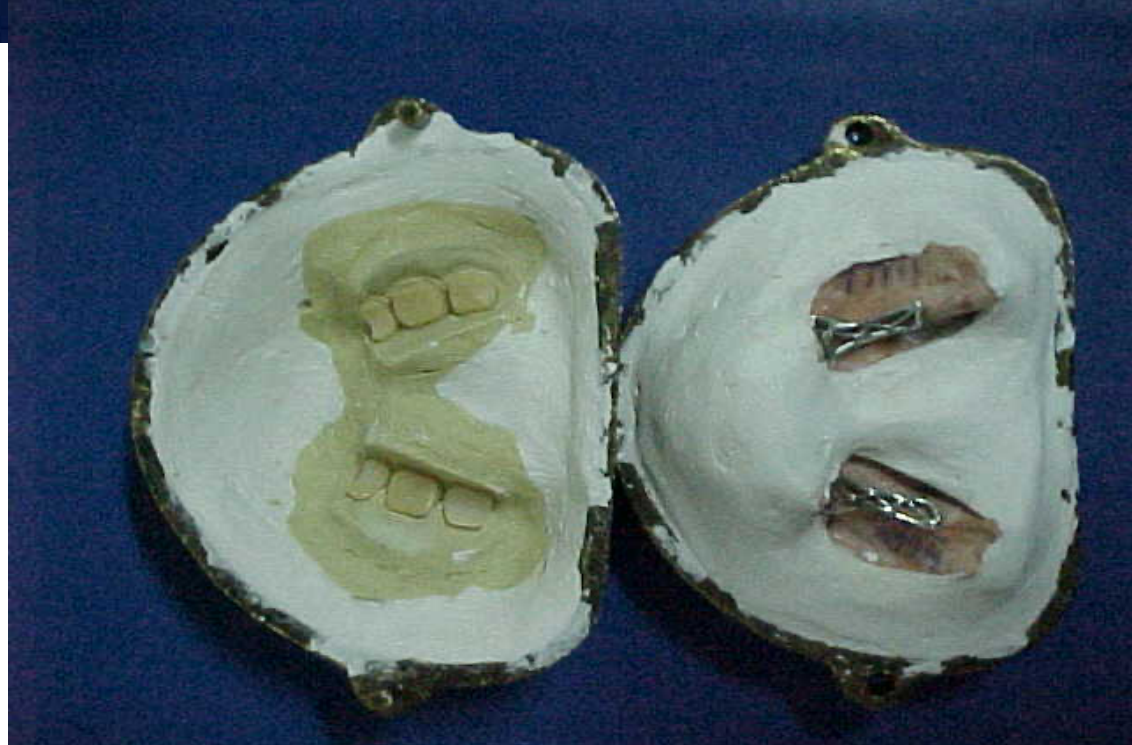
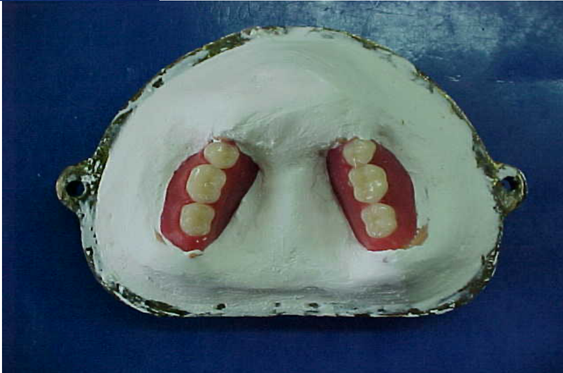
Processing the Denture24
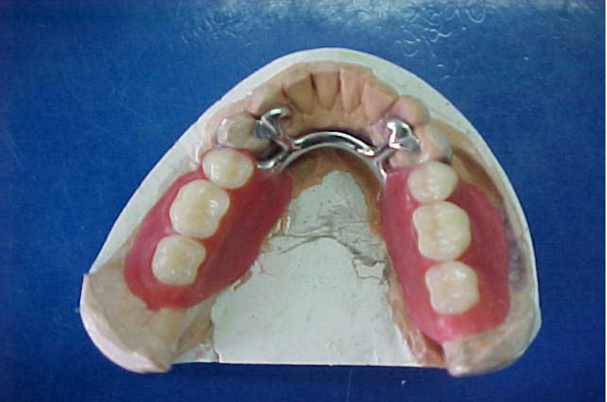
The final processing of the denture involves transitioning the wax-up into the final acrylic resin. This includes:
- Investing the framework and wax setup into a flask.
- Wax elimination and acrylic resin packing.
- Final processing and recovery of the denture from the flask.
- Quality Check: Assess denture base for voids, porosity, sharp projections, or acrylic nodules before insertion.
- Remove excess acrylic chairside.
Denture Insertion25
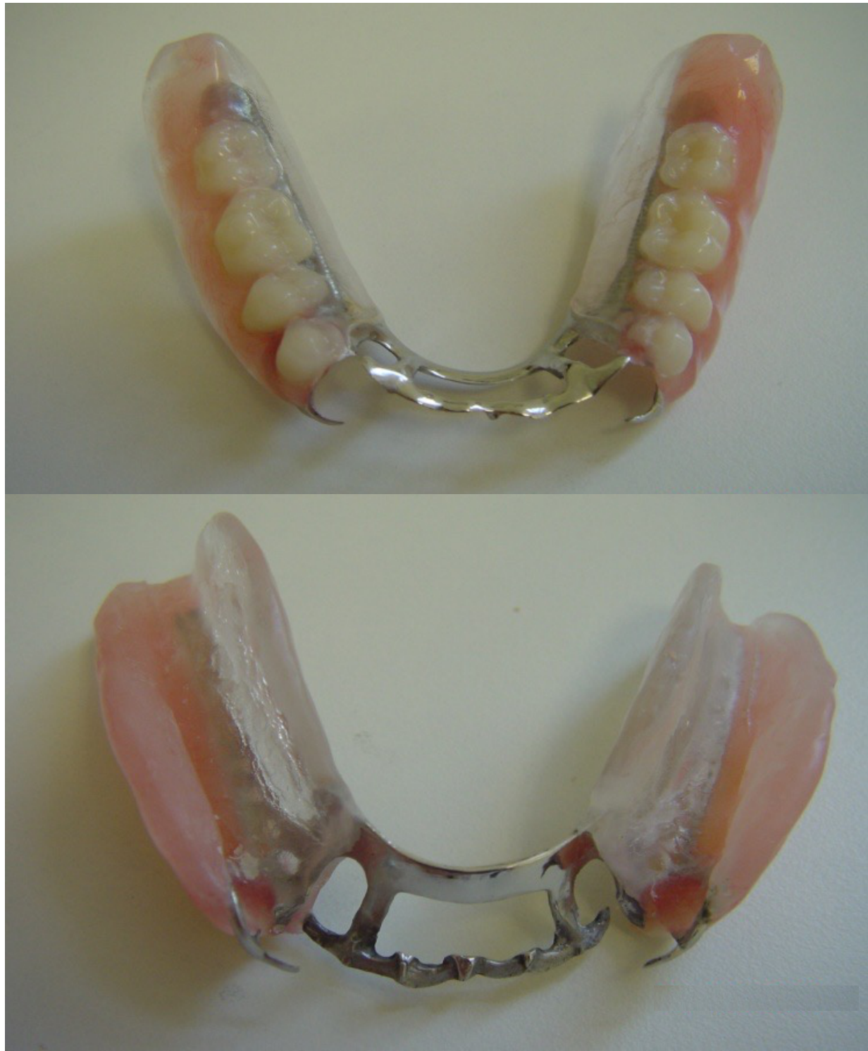
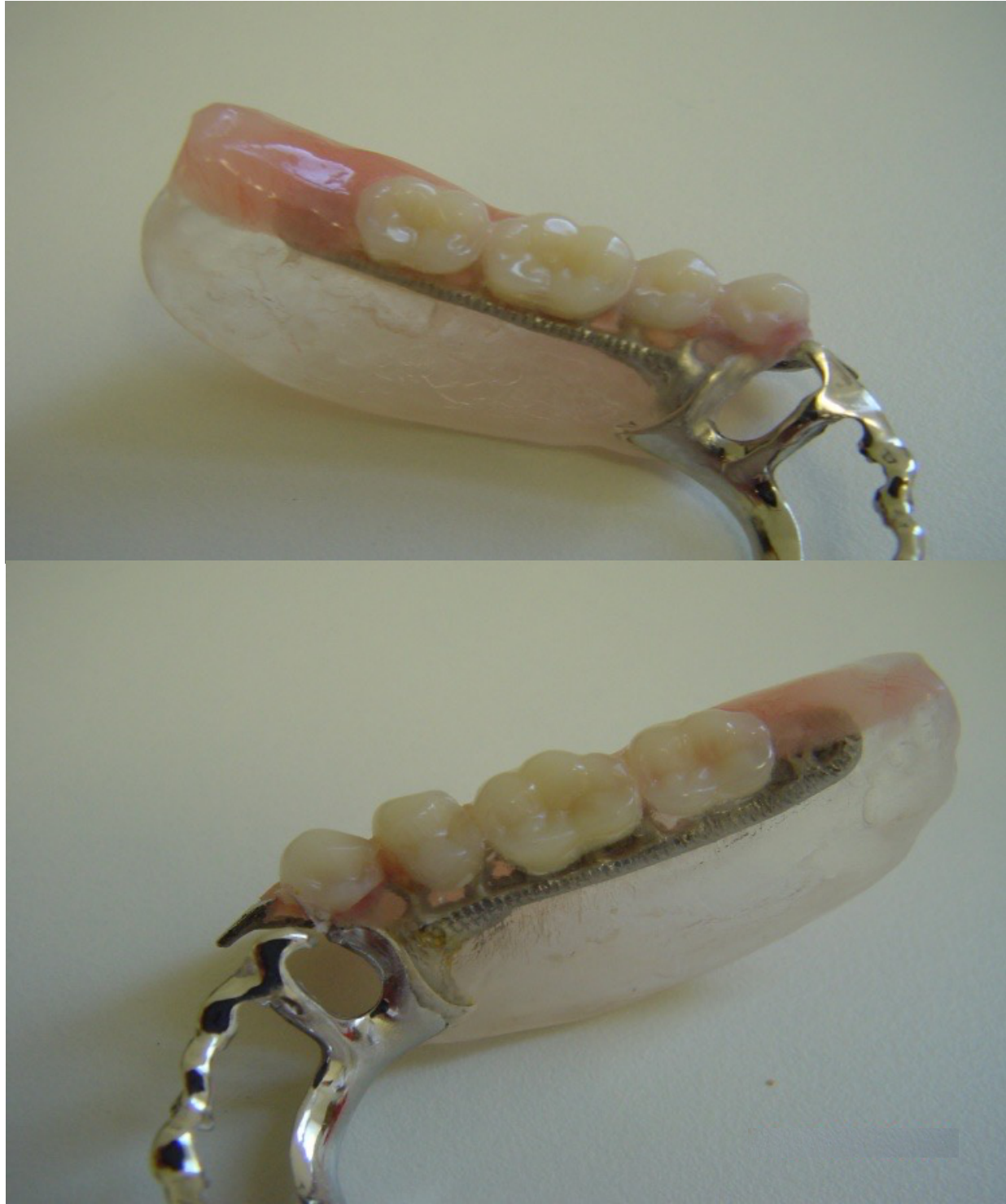
The insertion of a Removable Partial Denture (RPD) represents the clinical stage where the prosthesis is fitted into the patient’s mouth and evaluated for accuracy, comfort, and function.
Insertion Evaluation
During the insertion phase, the clinician must perform a systematic evaluation of the prosthesis to ensure it meets all clinical requirements and patient comfort standards.
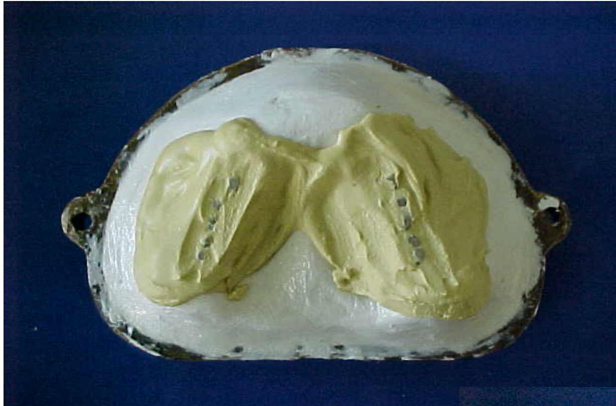
- Before inserting in the mouth, assess the quality of the denture base.
- Round sharp edges or trim overextensions chairside to prevent pain.
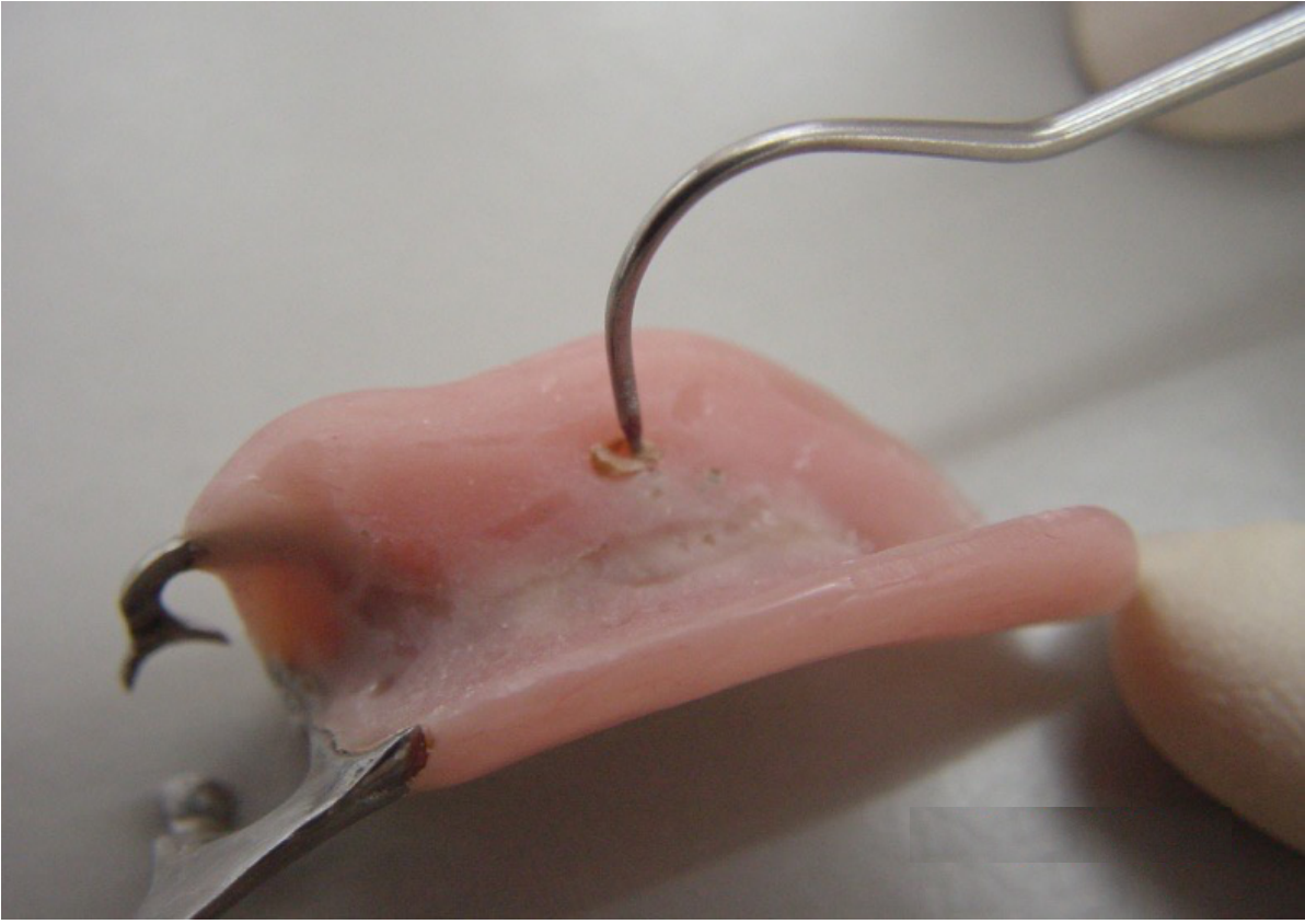
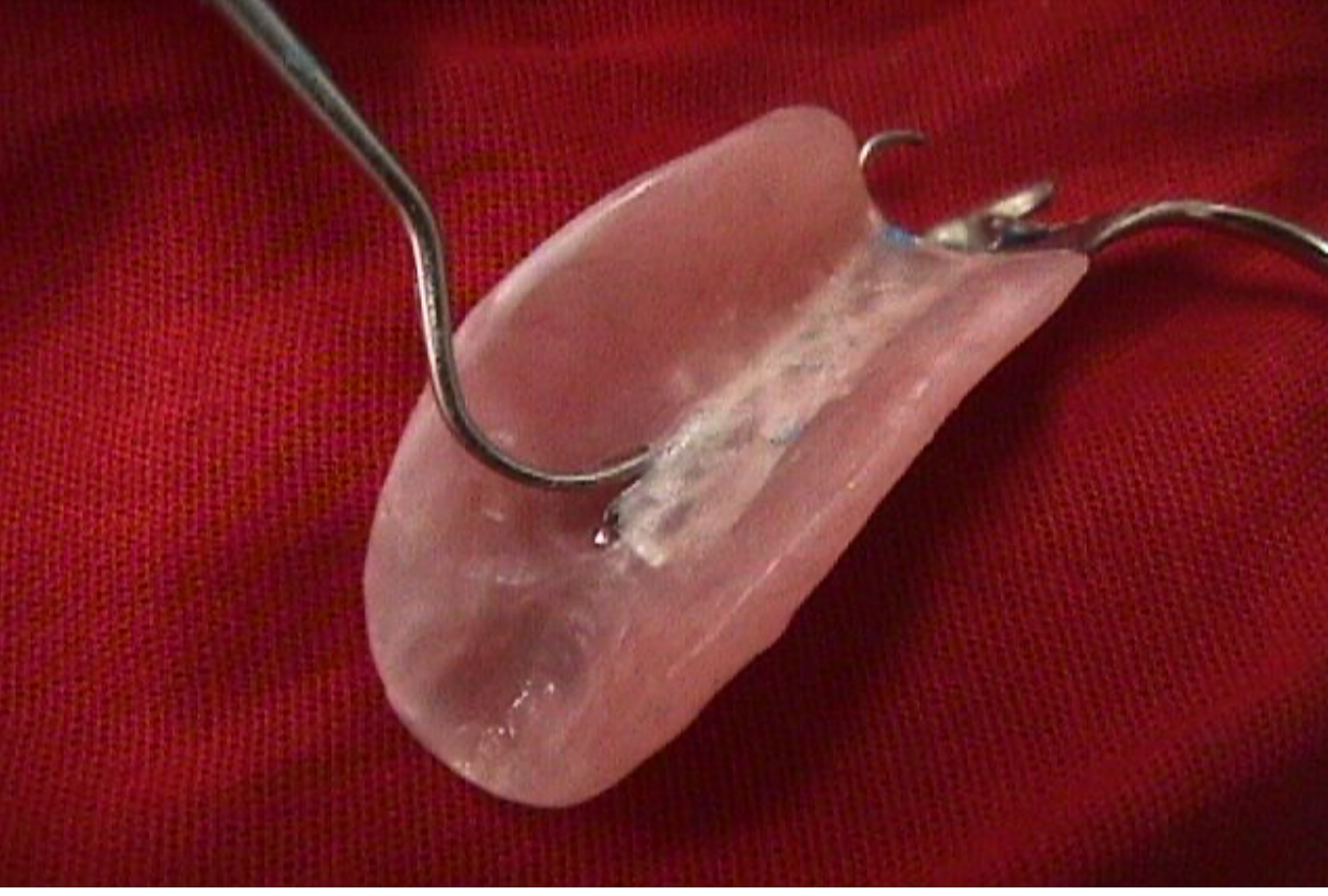
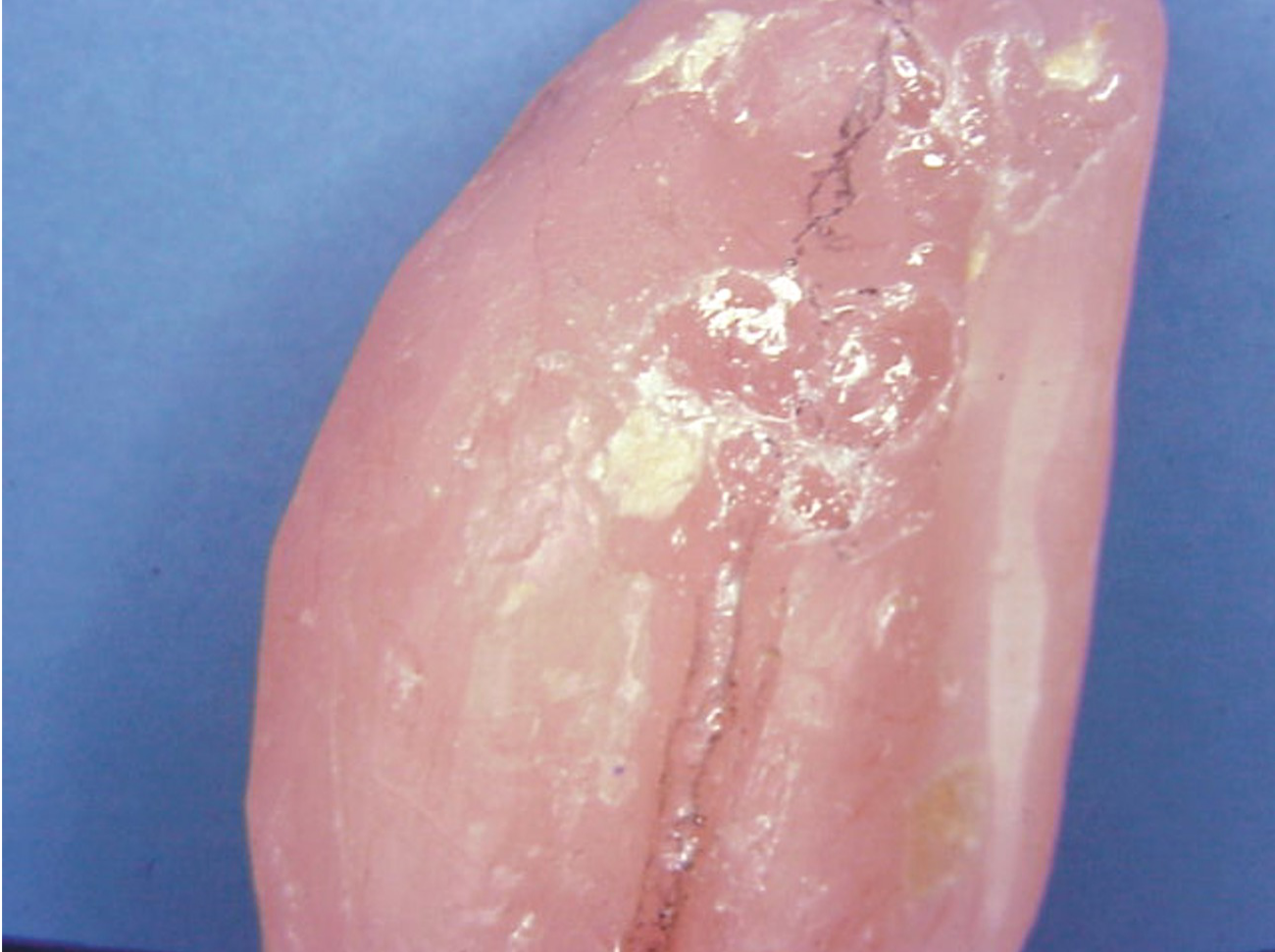
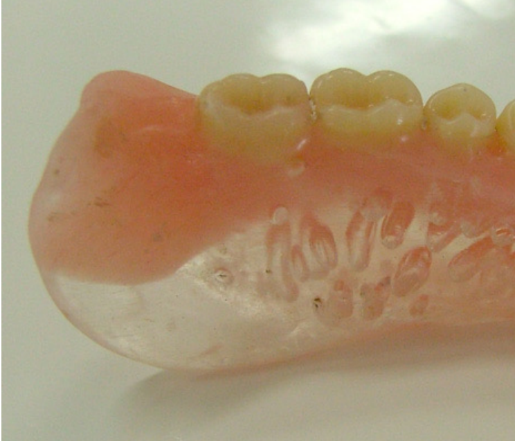
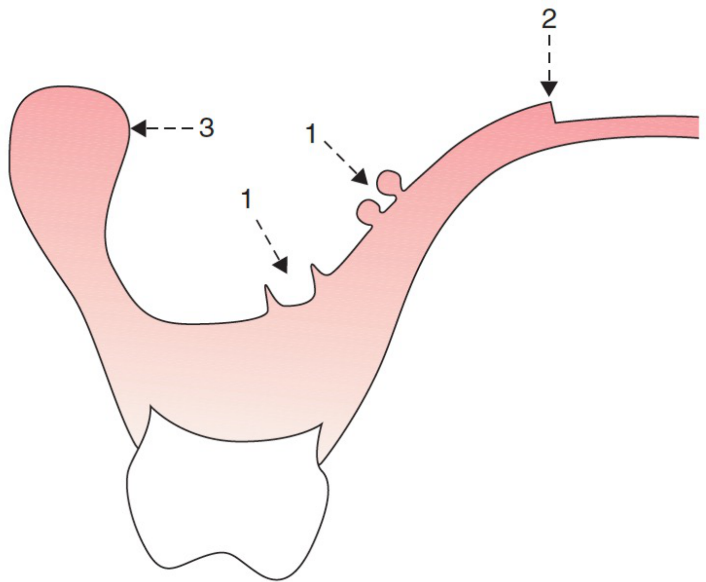
Defects on the Denture Base
Surface and Structural Irregularities
The denture base must be inspected for manufacturing flaws that can compromise hygiene or cause tissue irritation:
-
Voids and Porosity: Small holes or air bubbles trapped within the acrylic resin, which can harbor bacteria or weaken the base.
-
Surface Imperfections: Small imperfections or irregularities on the pink base material that require smoothing.
-
Structural Defects: Visible cracks or lines within the material that may indicate a risk of fracture.
-
Voids/Porosity: If present, send back to the lab for repair.
-
Nodules: Caused by defects on the model; remove chairside.
-
Overextensions: Trim if necessary.

Common Causes of Pain
Mechanical Irritants
Several specific defects on the denture base are primary contributors to patient discomfort and localized pain:
- Sharp Projections and Acrylic Nodules: Small, hard protrusions on the fitting surface resulting from imperfections in the stone cast.
- Sharp Edges: Rough or unpolished borders that can abrade the soft tissues.
- Overextension into Bony Undercuts: Extensions of the base that impinge upon bony prominences, leading to pressure sores and significant pain.
Adjustment Strategy
- Do not adjust the denture base extensively at the insertion appointment.
- Wait for the review appointment to confirm real problems as patients may not report discomfort initially.
- Identify trauma points using fit checker or light body impression material (perforations indicate strong contact).
- Correct with an acrylic bur in a straight handpiece, trimming little by little at review appointments.
Functional and Aesthetic Assessment
Clinical Evaluation Criteria
A successful insertion requires the assessment of the following factors:
-
Physical Retention: The ability of the RPD to resist removal forces.
-
Stability: The resistance to displacement by functional forces.
-
Extension of the Denture Bases: Checking for both over-extension (causing soreness) and under-extension (reducing support).
-
Occlusal Contact: Ensuring proper tooth-to-tooth contact between the RPD and opposing dentition.
-
Occlusal Vertical Dimension (OVD): Verifying the height of the bite is correct.
-
Appearance: Assessing the aesthetic integration of the prosthesis with the patient’s natural features.
-
Occlusion: Recheck occlusal contacts with articulating paper.
-
OVD: Reassess Occlusal Vertical Dimension (processing distortions can move teeth).
-
Appearance: Final assessment of aesthetics.
Saddle Adjustment and Relining
Saddle Refinement
Adjustment of the saddles is necessary to ensure the denture base fits the contours of the edentulous ridges accurately without causing impingement or instability.
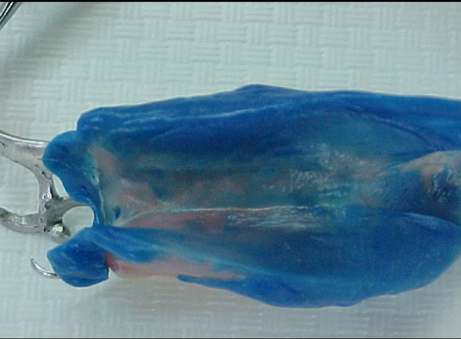
- Problem: Poor adaptation over the alveolar ridge (often if altered cast technique was not used).
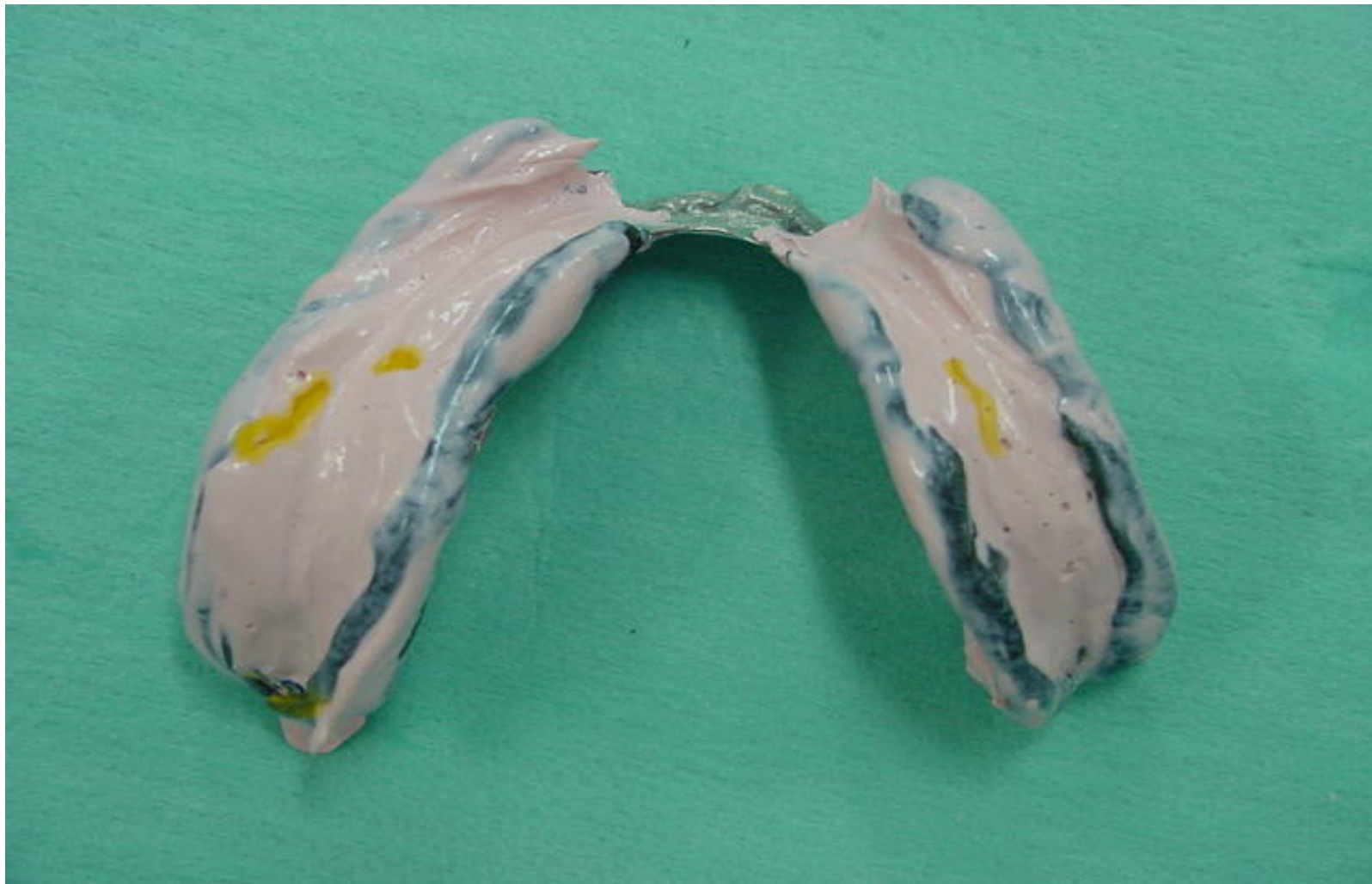
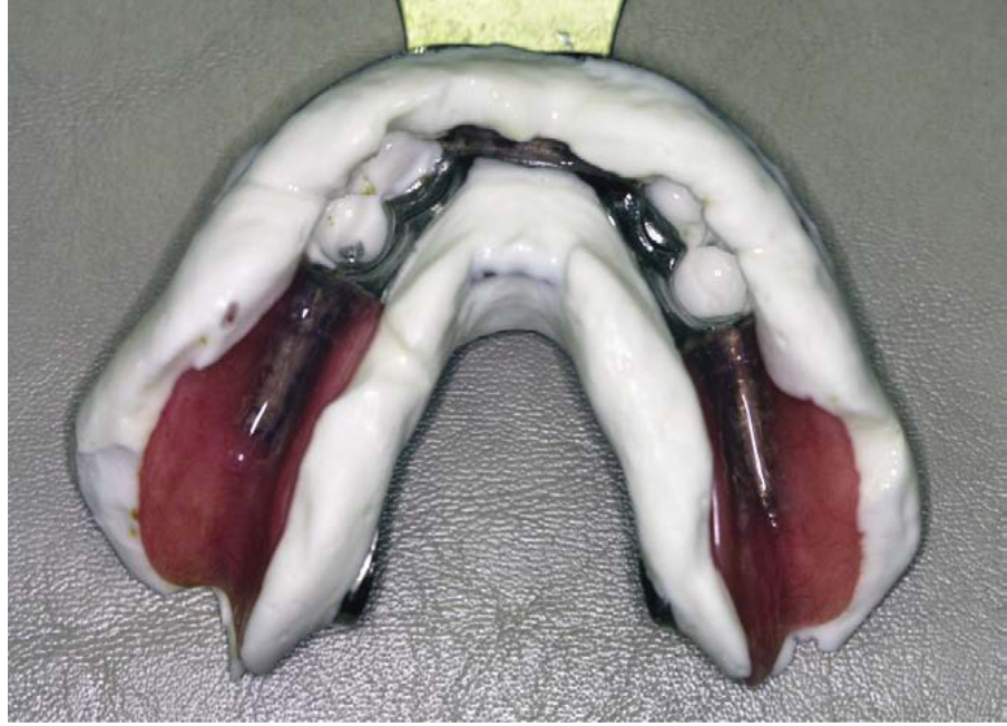
- Material: Use PVS (or zinc oxide eugenol) to reline.
- Technique: Same as altered cast impression (apply forces on rests, retract cheeks/tongue).
Pick Up Impression for Relining
Relining Procedures
When a denture is not well adapted to the alveolar ridge, a reline of the denture base is required. This is particularly common in Mandibular Class I and Class II cases where ridge resorption has occurred.
Impression Technique
A pick-up impression is utilized to capture the relationship between the existing denture and the current state of the soft tissues to facilitate the relining process.
Critical Step
- Get the bite registration BEFORE doing the pickup impression.
- Reasoning: The denture may come out with the impression; bite registration ensures the relationship is captured.
- Procedure: After relining impression, take a pickup impression of the denture using alginate and a stock tray.
Occlusal Contact Issues
Identification of Occlusal Discrepancies
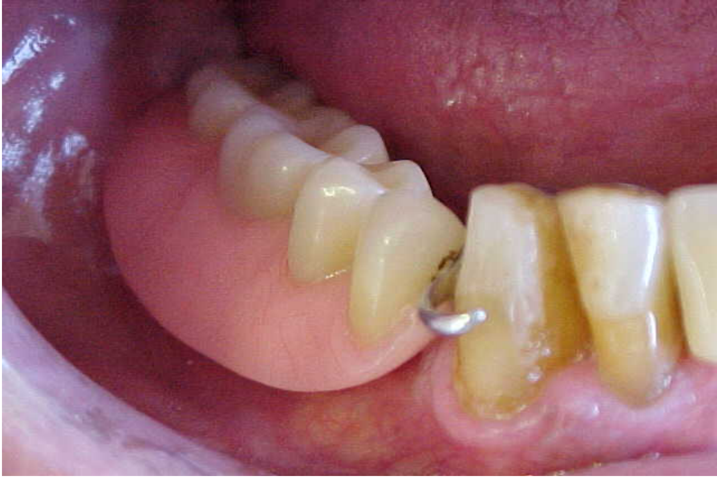
Inadequate occlusal contacts may manifest in the following ways:
-
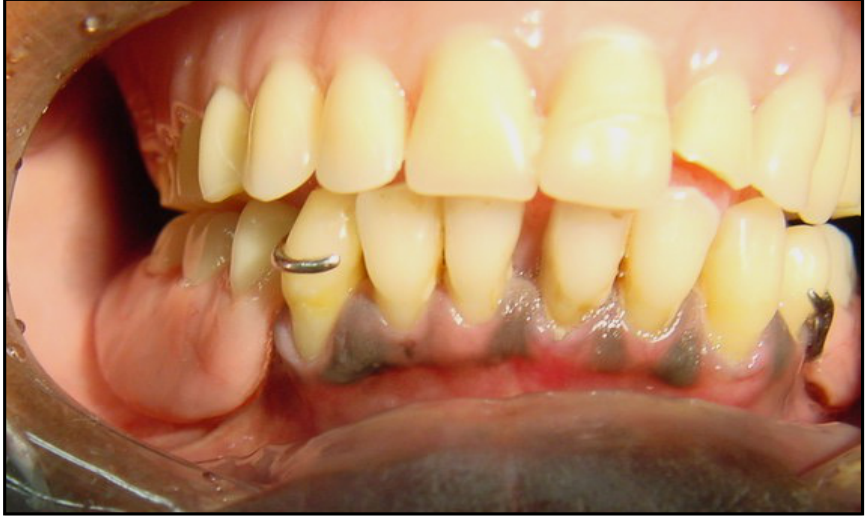
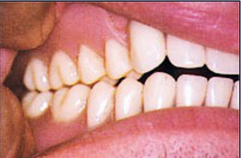
Open Bite in the Edentulous Area: The prosthetic teeth are positioned below the occlusal plane, failing to make contact with the opposing arch.
-
High Occlusal Vertical Dimension (OVD): The prosthetic teeth are positioned too high, causing premature contact and increasing the vertical dimension of the bite beyond the desired level.
-
Anterior Disocclusion: Acrylic teeth are too high, causing anterior open bite.
-
Correction: Mount the denture back on the articulator using a new model (created from the pickup impression).
-
Minor Open Bite: May be adjusted chairside.
-
Edentulous Space Open Bite: Requires pickup impression and lab fix.
Workflow Summary and Closing
Integrated Clinical and Laboratory Phases26
The production of a Cobalt-Chromium (Co-Cr) Removable Partial Denture (RPD) requires a synchronized sequence of clinical appointments and laboratory procedures.
| Clinical Phase | Laboratory Phase |
|---|---|
| Clinical Examination, Occlusal analysis, and Alginate impressions (upper and lower) | Fabrication of upper and lower Study models |
| Facebow record and Maxillo-Mandibular Relationship (MMR) | Duplication of Study models; Fabrication of Base & Rim (if required) |
| Mounting of models on articulator | |
| Diagnostic Assessment and Diagnostic workup/wax-up | |
| Mouth preparation and Survey Crowns (if required) | Survey of Study model and Design of framework; Fabrication of Special tray (on Study model) |
| Final Impression | Beading and Boxing; Creation of Master Model |
| Creation of Duplicate Master Model (Processing model) | |
| Survey of Master model; Block out Undercuts on Master model | |
| Creation of Duplicate block out model (Investment model) | |
| Cast Framework (on Investment model) | |
| Framework try-in | |
| MMR with base and rim attached to the framework; Altered cast technique (if required) | Mount Master Models on articulator (Cross Mount Processing Model) |
| Denture try-in | Tooth setting |
| Denture insertion | Denture processing |
Comprehensive Workflow for Co-Cr RPD27
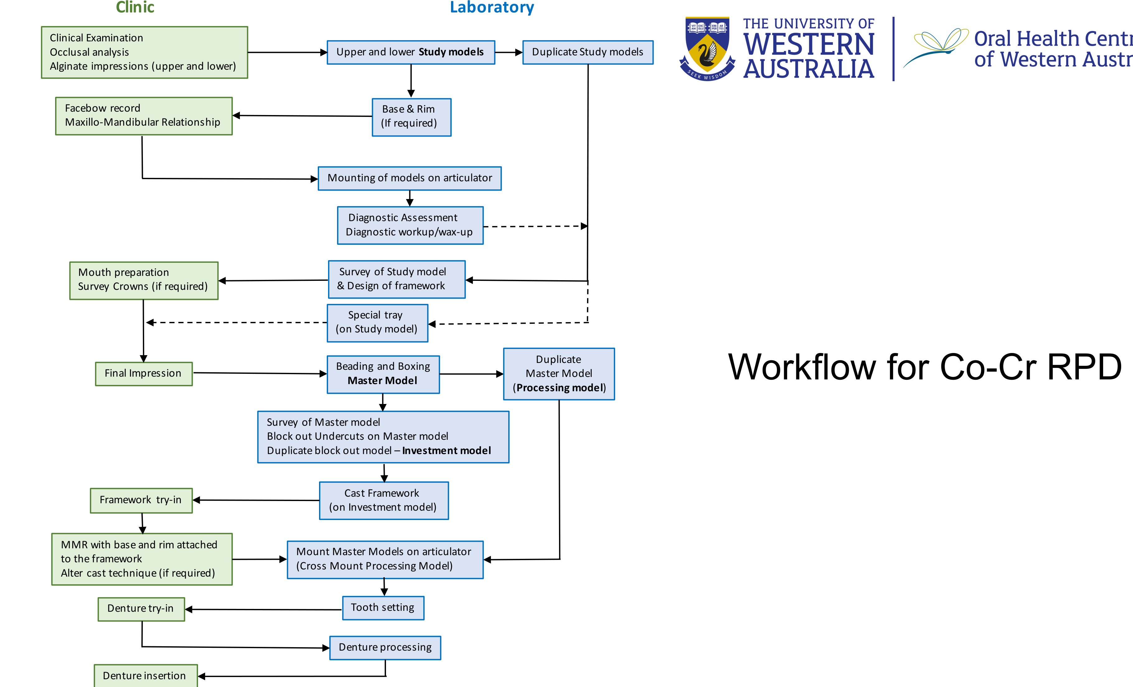
Sequential Workflow Logic
- Initial Assessment: Clinical exams and impressions lead to study models, which are then duplicated and mounted using facebow records for diagnostic workups.
- Design and Preparation: The diagnostic workup informs the survey and design of the framework. This guides clinical mouth preparation and the fabrication of custom special trays.
- Master Cast Production: Final impressions are processed into a Master Model. This model is duplicated to create a Processing Model and an Investment Model (after blocking out undercuts).
- Framework Fabrication: The framework is cast on the investment model and then returned to the clinic for try-in.
- Registration and Setting: Following framework try-in, MMR is recorded using the framework. Models are cross-mounted for tooth setting.
- Finalization: After a successful denture try-in, the laboratory completes denture processing for final clinical insertion.
Workflow Dependencies and Clinical Nuances
Each step relies on the accuracy of the previous one. Errors in impression taking or mouth preparation manifest during framework try-in or insertion. Proper planning on study models minimizes clinical adjustments later in the sequence.
Additional Clinical Considerations:
- Mouth preparation includes survey crowns, rest seats, and guide planes
- Try-in evaluation includes neutral zone and aesthetics
- Insertion phase may require adjustments or relining if needed
Thank you
Footnotes
-
Original PDF page 1: L9 Clinical Sequence for RPD, p.1 ↩
-
Original PDF page 2: L9 Clinical Sequence for RPD, p.2 ↩
-
Original PDF page 3: L9 Clinical Sequence for RPD, p.3 ↩
-
Original PDF page 9: L9 Clinical Sequence for RPD, p.9 ↩
-
Original PDF page 10: L9 Clinical Sequence for RPD, p.10 ↩
-
Original PDF page 11: L9 Clinical Sequence for RPD, p.11 ↩
-
Original PDF page 12: L9 Clinical Sequence for RPD, p.12 ↩
-
Original PDF page 14: L9 Clinical Sequence for RPD, p.14 ↩
-
Original PDF page 13: L9 Clinical Sequence for RPD, p.13 ↩
-
Original PDF page 15: L9 Clinical Sequence for RPD, p.15 ↩
-
Original PDF page 16: L9 Clinical Sequence for RPD, p.16 ↩
-
Original PDF page 18: L9 Clinical Sequence for RPD, p.18 ↩
-
Original PDF page 19: L9 Clinical Sequence for RPD, p.19 ↩
-
Original PDF page 20: L9 Clinical Sequence for RPD, p.20 ↩
-
Original PDF page 21: L9 Clinical Sequence for RPD, p.21 ↩
-
Original PDF page 22: L9 Clinical Sequence for RPD, p.22 ↩
-
Original PDF page 26: L9 Clinical Sequence for RPD, p.26 ↩
-
Original PDF page 25: L9 Clinical Sequence for RPD, p.25 ↩
-
Original PDF page 29: L9 Clinical Sequence for RPD, p.29 ↩
-
Original PDF page 30: L9 Clinical Sequence for RPD, p.30 ↩
-
Original PDF page 31: L9 Clinical Sequence for RPD, p.31 ↩
-
Original PDF page 34: L9 Clinical Sequence for RPD, p.34 ↩
-
Original PDF page 35: L9 Clinical Sequence for RPD, p.35 ↩
-
Original PDF page 37: L9 Clinical Sequence for RPD, p.37 ↩
-
Original PDF page 38: L9 Clinical Sequence for RPD, p.38 ↩
-
Original PDF page 45: L9 Clinical Sequence for RPD, p.45 ↩
-
Original PDF page 46: L9 Clinical Sequence for RPD, p.46 ↩