Connectors12
Overview of Removable Partial Denture Components
This section covers the essential elements of dental prosthetic frameworks, specifically focusing on:
- Major Connectors: The primary components that unite the various parts of the prosthesis into a single unit.
- Minor Connectors: The components that serve as the link between the major connector and other units of the prosthesis, such as rests, clasps, or indirect retainers.
Learning Outcomes3
Upon completion of this section, students should be able to:
- Discuss the function and design considerations of Major Connectors.
- Describe the different types of Maxillary and Mandibular major connectors and their specific clinical indications.
- Discuss the function of Minor connectors within the prosthetic framework.
- Identify a minor connection in the metal framework.
- Apply biomechanical principles to design frameworks that distribute forces effectively and preserve periodontal health
Major Connectors4567891011
Definition and Concept
A major connector is a rigid structure that joins the components on one side of the arch with those on the opposite side (GPT-9, 2017).
All other Removable Partial Denture (RPD) components are directly or indirectly attached to it.
Primary Functions
According to McCracken’s (13th edition, 2016), the functions include:
- Union of RPD components (direct or indirect)
- Distribution of applied force throughout the arch to selected teeth and tissues
- Minimization of torque to individual teeth
- Control of prosthesis movement (Cross-arch stability)
- Assistance with indirect retention
- Periodontal Preservation: A rigid connector with adequate surface area reduces load on individual teeth, thereby preserving periodontal support.
Rigidity and Design Considerations
Rigidity is essential to distribute forces and ensure all other components of the RPD are effective.
Consequences of a Flexible Major Connector:
- Damage to hard and soft tissues.
- Concentration of forces on individual teeth and segments of residual ridges.
- Resultant tooth mobility, tooth loss, and bone resorption.
- Decreased support for associated denture bases.
Favorable Location Requirements
- Must be free of movable tissue.
- Avoid impingement of gingival tissues (gingival margin).
- Avoid tori and soft tissue prominences.
- Provide relief beneath the major connector in areas of possible interference, such as the median palatal suture.
Palatal Raphe Relief
The midline palatal suture often presents with prominent, rigid tissue. Relief is required beneath the connector in this region to prevent instability and discomfort.
Structural Geometry
- Major connectors should feature rounded angles to ensure patient comfort and structural integrity.
Border Placement and Gingival Clearance
Borders of major connectors must be kept far from the gingival margin:
- Mandible: At least 3–4 mm from the gingival margin and the floor of the mouth.
- Maxilla: At least 5–6 mm from the gingival margin; must avoid the torus and soft palate.
Tissue Adaptation
- The design must maintain the natural contour of the subjacent structures.
- Surface Contour: Maintain smooth, natural palatal contours without decorative patterns or rugae simulation, as irregularities cause tongue irritation and denture instability.
Classification of Major Connectors
Major connectors are categorized by the dental arch they serve:
- Maxillary
- Mandibular
Maxillary Major Connectors1213
Principles of Maxillary Design
- Intimate contact between the major connector and palatal mucosa improves retention and stability.
- Support Correlation: The lower the periodontal support of remaining teeth, the greater the required palatal coverage.
- Dimensions: The wider the major connector, the thinner it can be. Conversely, the narrower the connector, the thicker it must be to maintain rigidity.
Common Maxillary Types
- Single palatal strap
- Anterior-posterior palatal strap
- U-shaped palatal connector
- Broad palatal strap or Palatal plate
- Single palatal bar
- Anterior-posterior palatal bar
Single Palatal Strap14
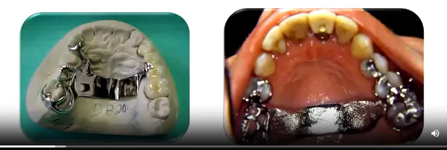
Characteristics and Indications
- Usage: Generally used for Class III cases with or without modifications (provided there is no anterior modification).
- Dimensions: Designed thin for tongue comfort but must be wide enough (≥ 8 mm) for rigidity.
- Border Placement:
- The anterior border should follow the valleys of the rugae but avoid crossing over them.
- Both anterior and posterior borders must cross the suture line at right angles.
- Biomechanical Advantage: Crossing at 90° provides optimal rigidity compared to oblique crossings.
- Function: Provides indirect retention when the denture base is located on one side of the arch.
Anterior Posterior Palatal Strap15
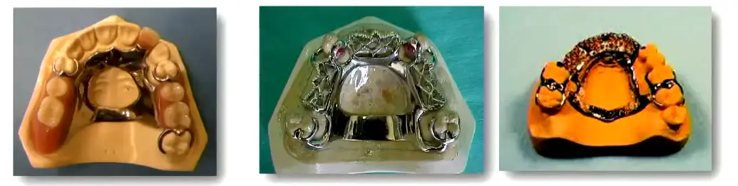
Design and Contraindications
- Structure: A combination of anterior and posterior straps.
- Indications: Class II, Class III with anterior modification, and Class IV cases.
- Dimensions: Flat profile and at least 8 mm wide.
- Placement: The posterior strap should be positioned anterior to the hard/soft palate junction.
- Contraindications: Inoperable torus extending to the soft palate
- Phonetics: Minimize coverage of the anterior rugae region to preserve sibilants (/s/, /z/) and alveolar sounds (/t/, /d/).
- Placement: Avoid the vibrating line (soft palate junction) to prevent gagging and instability..
U Shaped Palatal Connector16
Horseshoe/U shaped Design Considerations
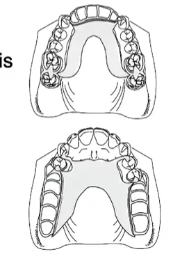
- Indications:
- Inoperable large palatal torus.
- Common with Class IV (missing anterior teeth with posterior teeth present).
- Patients with a significant gag reflex.
- Limitations:
- Poorest design for rigidity.
- Requires bulk in the rugae zone where tongue space and freedom are most needed.
Palatal Plate or Full Palatal Coverage1718
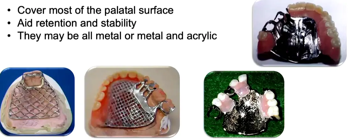
Full Palatal Coverage Characteristics
- Designed to cover most of the palatal surface.
- Aids significantly in retention and stability.
- Material options include all-metal constructions or combinations of metal and acrylic.
Clinical Indications for Palatal Plates
- Cases with few remaining teeth (e.g., only an anterior arrangement).
- Remaining teeth have a guarded prognosis.
- Presence of long, flat residual ridges.
- Thermal Conductivity: Metal plates allow temperature sensation, improving patient adaptation and taste perception compared to acrylic.
- Relining Capability: Only designs incorporating acrylic coverage (mesh frameworks) allow for future relining; solid metal requires remaking if tissue changes.
Single Palatal Bar1920
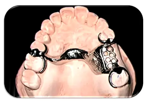
Single Palatal Bar Specifications
- Shape: Narrow with a half-oval cross-section.
- Dimensions: Less than 8 mm in width.
- Indications: Class III cases with small edentulous areas.
Disadvantages:
- Discomfort: Bulky profile; should not be placed anterior to the 2nd premolar.
- Support: Provides low vertical support.
- contraindicated for Class I and Class II cases
Bar Placement Locations
- Anterior: Located in the area of the palatal rugae.
- Median: Positioned behind the palatal rugae (Ideal location).
- Posterior: Placed at the junction of the hard and soft palate.
Anterior Posterior Palatal Bar21
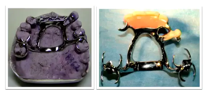
Double Bar Design
- Structure: Combination of anterior and posterior bars; the anterior portion is typically less bulky. Includes two flat longitudinal elements on each side.
- Indications:
- Absence of many teeth (both anterior and posterior).
- Presence of a palatal torus.
- Patient Experience: Can be uncomfortable due to multiple borders.
Advantages:
- Minimizes soft tissue coverage.
- Provides high rigidity.
Selection Considerations for Maxillary Major Connectors22
Clinical Selection Criteria
- Weak Periodontal Support: Palatal Strap or Complete Palate is indicated to maximize coverage.
- Adequate Periodontal Support: Palatal Strap or Anteroposterior Palatal Bar is indicated.
- Long Span Distal Extension: Anteroposterior Strap or Complete Palate is required for critical rigidity.
- Anterior Tooth Replacement: Anteroposterior Palatal Strap, Horseshoe, or Complete Palate.
- Presence of Torus: Anteroposterior Palatal Strap, Bar, or Horseshoe.
- Usage Notes:
- Palatal Bar: Rarely indicated due to lack of rigidity and vertical support.
- Horseshoe: Used sparingly due to reduced rigidity.
Bead Lines23
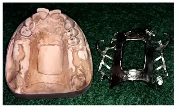
Purpose and Technical Execution
- Location: Placed at the borders of maxillary major connectors.
- Functions:
- Prevents collection of food particles under the connector.
- Displaces adjacent soft tissues to produce a mechanical seal.
- Technical Procedure: Performed on the master cast by a technician using a spoon excavator or round bur (0.5 x 1 mm). The line should fade out 6 mm from the gingival margins.
Clinical Protocol
Bead lines are unnecessary for narrow bars where food trapping is unlikely. The clinician must explicitly specify the requirement for bead lines to the laboratory technician.
Mandibular Major Connectors2425
General Principles for Mandibular Design
- Mandibular connectors provide limited support but can assist in indirect retention.
- Anatomical Clearance: Must not invade the floor of the mouth, lingual frenulum, or mandibular tori area.
- Relief Requirements:
- Kennedy Class III (Teeth supported): No relief or small relief necessary.
- Kennedy Class I, II, IV: Moderate relief required (approximately 1.5 mm).
- Note: No bead lines are required for mandibular connectors
Mandibular Tissue Interface
The lingual mucosa is non-keratinized and subject to vertical movement. Unlike the maxilla, the mandibular major connector does not provide vertical support; support derives entirely from the teeth and denture base. .
Common Mandibular Types
- Lingual bar
- Lingual plate
- Sublingual bar
- Cingulum bar
- Double lingual bar (Kennedy bar)
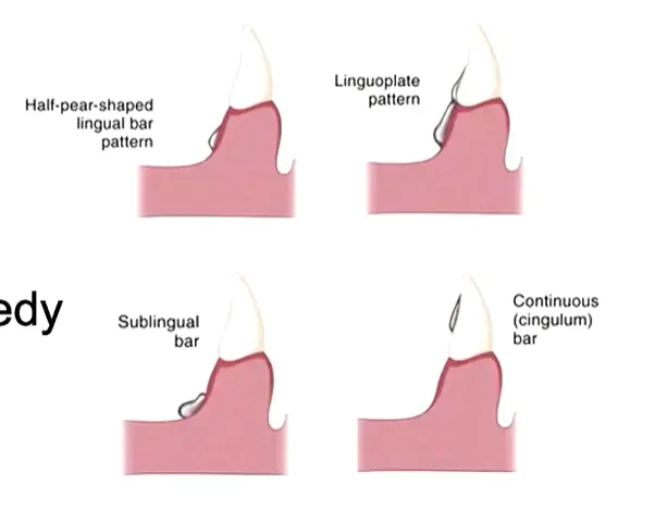
Lingual Bar2627
Structural Shape
- Cross-section: Half-pear shape.
- Borders:
- Superior border: Tapered toward the gingival tissue.
- Inferior border: Represents the broadest portion of the bar.
Space Requirements and Indications
- Vertical Space: Requires at least 8 mm of space between the free gingival margin and the floor of the mouth.
- The bar itself requires a minimum height of 5 mm.
- A 3 mm clearance from the gingival margin must be maintained.
- Indications: Suitable for any case where sufficient vertical space is available
- Measurement: Use a periodontal probe to establish the functional depth of the lingual sulcus during design.
- Advantage: Allows the tongue to maintain contact with the lingual surfaces of teeth, providing natural cleansing action..
Lingual Plate2829
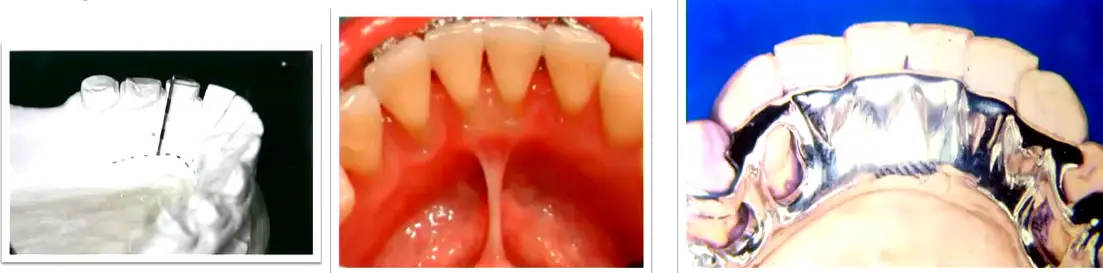
Design and Indications
- Structure: A thin metal sheet that adapts intimately to the cingula of the teeth.
- Indications:
- Shallow floor of the mouth.
- Presence of an inoperable mandibular torus (where space for a lingual bar is insufficient).
- High frenum attachment.
Clinical Evaluation
Advantages:
- Effective for providing indirect retention.
- Helps stabilize teeth with guarded prognoses.
Disadvantages:
- Potential to irritate underlying soft tissues.
- Increased risk of caries if the patient has poor oral hygiene.
- Biological Risk: Alters plaque biology; requires rigorous patient compliance and completion of the control phase (hygiene) before placement.
Cingulum Bar30
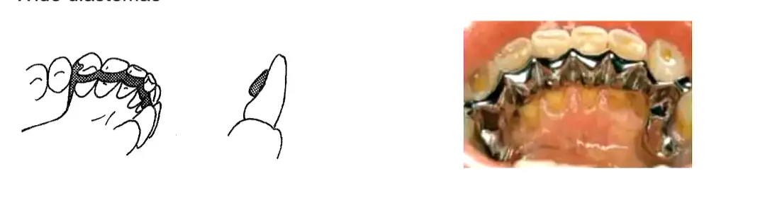
Requirements and Contraindications
- Usage: Can only be used if clinical crowns are long enough and other alternatives are not feasible. Contraindications:
- Retroclined anterior teeth.
- Presence of wide diastemas.
Double Lingual Bar3132
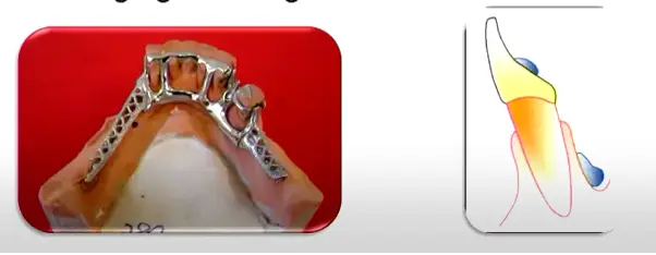
Design and Advantages
- Structure: Consists of a standard lingual bar with a secondary bar positioned above the cingulum.
- Function: The secondary bar acts as an indirect retainer.
Advantages:
- Exposes most of the lingual surface of the teeth and interproximal soft tissue.
- Allows for natural stimulation of the gingival margins.
Limitations of the Kennedy Bar
Disadvantages:
- Tendency to trap food debris, especially if marked crowding leads to poor adaptation.
- Potential for tongue irritation due to multiple borders.
- Force Distribution: Distributes oblique loads across multiple teeth rather than concentrating them on single rests.
- Repairability: If one rest seat fails, the framework can often be modified to add a new rest without remaking the entire prosthesis.
- Contraindication: Cannot be used when diastemas exist as the metal would be visible through the gaps.
Sublingual Bar33
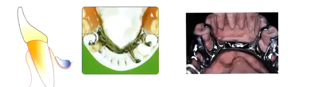
Placement and Indications
- Design: Essentially a lingual bar placed more posteriorly and inferiorly.
- Positioning: Lies over and parallel to the anterior floor of the mouth.
- Indications:
- Shallow floor of the mouth.
- Presence of lingual undercuts.
- Low frenulum attachment.
- lingual tori
Minor Connectors34
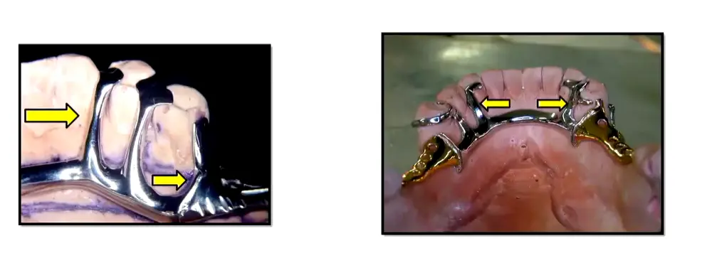
Minor connectors serve as the connecting links between the major connector or base of a removable partial denture (RPD) and the other units of the prosthesis, such as clasp assemblies, indirect retainers, or denture bases.
Functions3536
Minor connectors serve to join the remaining components of a Removable Partial Denture (RPD) to the major connector, specifically:
- Clasp assemblies
- Indirect retainers (auxiliary rests)
Force Distribution and Reciprocation37
Minor connectors play a critical role in the mechanical stability of the prosthesis by:
-
==Horizontal Stabilization: Positioned interdentally, minor connectors resist horizontal movements of the denture.==
-
==RPI Reciprocation: In RPI designs (Rest seat, Proximal plate, I-bar), the minor connector and proximal plate provide the reciprocating function, eliminating the need for a separate reciprocal arm.==
-
Distributing applied forces to the supporting teeth and oral tissues.
-
Assisting in reciprocation during the placement and removal of the denture.
Joining Denture Base to Major Connector38
Minor connectors are utilized to join the denture base to the major connector, often taking the form of a metal gridwork to ensure a secure mechanical bond.
Load Transfer
The grid or meshwork transfers occlusal loads from the saddle to the major connector and subsequently to the opposite side of the arch.
Primary Attributes39
Structural Requirements
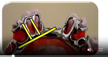
- Rigidity: Must be sufficiently rigid to transmit forces effectively.
- Angulation: Should form a right angle where they meet the major connector.
- Positioning: Preferably located within the interdental spaces to minimize tongue interference.
- Dimensions: Designed to be wider in the linguobuccal direction and narrower in the mesiodistal direction
- ==Gingival Protection: The narrow mesial-distal dimension is specifically designed to minimize coverage of gingival margins.==.
Minor Connectors Joining Denture Bases to Major Connector4041
Design and Extension
- Gridwork Construction: Utilizes a rigid framework that does not interfere with the placement of artificial teeth.
- Base Support: Provides adequate support and retention for the resin base.
- Anatomical Coverage:
- Maxilla: The connector should cover the tuberosity.
- Mandible: The connector should extend 2/3 the length of the edentulous ridge.
Minor connectors facilitate the attachment of the denture bases to the major connector, ensuring the stability of the prosthetic teeth and the resin foundation.
Cast Stop42
Purpose and Application
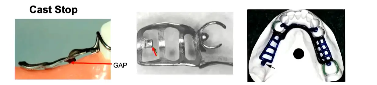
- Indications: Primarily used in Kennedy Class I and II (free-end saddles) cases.
- Definition: A small area of the minor connector that makes direct contact with the master cast.
- Function: Prevents displacement or deformation of the metal framework during the packing and processing of acrylic resin
- ==Tissue Contact Prevention: Without this stop, compression of acrylic would cause the metal to lift away from anterior tissues, resulting in gaps.==
- ==Acrylic Space: The grid maintains a gap from the tissue to allow acrylic to flow underneath; only the cast stop (tissue stop) touches the cast.==.
Location and Fabrication
- Placement: Located in the posterior region where the minor connector crosses the center of the ridge.
- Method: Created by removing wax at the point where the posterior strut of the minor connector crosses the center of the ridge.
Internal and External Finish Lines43
Resin-Metal Junctions
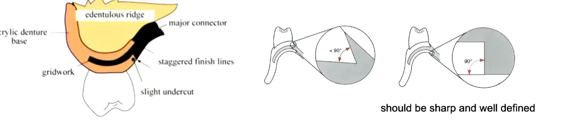
- Definition: The interfaces where the acrylic resin meets the metal framework are known as finish lines.
- Retention: These lines help mechanically lock the acrylic resin to the major connector.
- Transition: They provide a smooth, hygienic transition between the denture base and the metal framework
- ==Internal Finish Line: Forms a 90-degree butt joint with the acrylic to prevent thin, fragile edges prone to fracture and fungal colonization.==
- ==External Finish Line: Angled at less than 90 degrees (beveled) to provide mechanical retention for the acrylic veneer.==.
Denture Base444546
Functions of Saddles
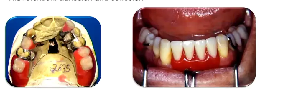
- Support and Tissue Replacement: Supports artificial teeth and replaces lost alveolar tissues.
- For distal extension cases (Kennedy Class I and II), maximum extension is critical to reduce load on abutment teeth.
- In the mandible, extend over two-thirds (2/3) of the edentulous space; in the maxilla, cover the tuberosity.
- Inadequate metal framework extension increases the risk of acrylic fracture between the terminal abutment and the end of the saddle.
- Force Distribution: Receives and distributes occlusal forces to the supporting structures, particularly in Kennedy Class I and II cases.
- Retention: Aids in the retention of the prosthesis through the physical forces of adhesion and cohesion.
Additional Functions of Saddles
- Tissue Stimulation: Stimulates the underlying tissues of the residual ridge, which helps to prevent alveolar ridge atrophy.
- Stability: Prevents the migration of remaining natural teeth.
- Esthetics: Provides a cosmetic effect by restoring natural contours.
Esthetic and Functional Contours
When the saddle involves the anterior region, the buccal flange must be contoured to provide proper lip support. This must be verified during the wax try-in phase, with explicit instructions to the laboratory to maintain the wax contour during processing.
The denture base can be constructed from different materials depending on the clinical requirements. The primary types used in removable partial denture construction are:
- Metallic
- Acrylic
Metallic47
Advantages of Metallic Bases
- Thermal Stimulus: Conducts temperature changes to the underlying tissues.
- Resistance: High strength and durability.
- Hygiene: Easy to clean and maintain.
- Reduced Bulk: Requires less volume/thickness compared to acrylic.
- Indicated for limited interarch space where there is insufficient vertical space for an acrylic base plus teeth.
- Reduced fungal infection risk (Candida colonization) compared to acrylic due to the non-porous surface.
Disadvantages of Metallic Bases
- Adjustment: Difficult to adjust once cast.
- Maintenance: Not able to be relined.
- Cost: Higher fabrication costs.
- Weight: Generally heavier than acrylic alternatives.
Acrylic48
Advantages of Acrylic Bases
- Weight: Lighter than metallic bases.
- Esthetics: Provides superior aesthetic results.
- Adaptation: Offers good adaptation to the underlying tissues.
- Maintenance: Provides the potential for future relining as the ridge resorbs.
- Standard material for denture bases, processed onto the metal framework via mesh or grid retention.
Disadvantages of Acrylic Bases
- Stability: Prone to distortion over time.
- Insulation: Does not provide thermal stimulus to the tissues.
- Hygiene: More porous and can be more difficult to keep clean compared to metal.
Maintenance and Longevity
- Brush with a soft brush daily and soak periodically in antimicrobial solutions like Chlorhexidine gluconate, diluted white vinegar, or peroxide-based cleaners.
- Sodium hypochlorite (bleach) is contraindicated for partial dentures as it may corrode metal components.
- Recommend replacement or relining every 4–5 years to maintain tissue adaptation and prevent bone resorption.
- Micro-porosity harbors microorganisms.
- Acts as a thermal insulator, meaning patients cannot sense food temperature as well as with metal palatal plates.
Thank you.
Footnotes
-
Original PDF page 1: L5 Major and Minor Connectors, p.1 ↩
-
Original PDF page 48: L5 Major and Minor Connectors, p.48 ↩
-
Original PDF page 2: L5 Major and Minor Connectors, p.2 ↩
-
Original PDF page 3: L5 Major and Minor Connectors, p.3 ↩
-
Original PDF page 4: L5 Major and Minor Connectors, p.4 ↩
-
Original PDF page 5: L5 Major and Minor Connectors, p.5 ↩
-
Original PDF page 6: L5 Major and Minor Connectors, p.6 ↩
-
Original PDF page 7: L5 Major and Minor Connectors, p.7 ↩
-
Original PDF page 8: L5 Major and Minor Connectors, p.8 ↩
-
Original PDF page 9: L5 Major and Minor Connectors, p.9 ↩
-
Original PDF page 10: L5 Major and Minor Connectors, p.10 ↩
-
Original PDF page 11: L5 Major and Minor Connectors, p.11 ↩
-
Original PDF page 12: L5 Major and Minor Connectors, p.12 ↩
-
Original PDF page 13: L5 Major and Minor Connectors, p.13 ↩
-
Original PDF page 14: L5 Major and Minor Connectors, p.14 ↩
-
Original PDF page 15: L5 Major and Minor Connectors, p.15 ↩
-
Original PDF page 16: L5 Major and Minor Connectors, p.16 ↩
-
Original PDF page 17: L5 Major and Minor Connectors, p.17 ↩
-
Original PDF page 18: L5 Major and Minor Connectors, p.18 ↩
-
Original PDF page 19: L5 Major and Minor Connectors, p.19 ↩
-
Original PDF page 20: L5 Major and Minor Connectors, p.20 ↩
-
Original PDF page 21: L5 Major and Minor Connectors, p.21 ↩
-
Original PDF page 22: L5 Major and Minor Connectors, p.22 ↩
-
Original PDF page 23: L5 Major and Minor Connectors, p.23 ↩
-
Original PDF page 24: L5 Major and Minor Connectors, p.24 ↩
-
Original PDF page 25: L5 Major and Minor Connectors, p.25 ↩
-
Original PDF page 26: L5 Major and Minor Connectors, p.26 ↩
-
Original PDF page 27: L5 Major and Minor Connectors, p.27 ↩
-
Original PDF page 28: L5 Major and Minor Connectors, p.28 ↩
-
Original PDF page 29: L5 Major and Minor Connectors, p.29 ↩
-
Original PDF page 30: L5 Major and Minor Connectors, p.30 ↩
-
Original PDF page 31: L5 Major and Minor Connectors, p.31 ↩
-
Original PDF page 32: L5 Major and Minor Connectors, p.32 ↩
-
Original PDF page 33: L5 Major and Minor Connectors, p.33 ↩
-
Original PDF page 34: L5 Major and Minor Connectors, p.34 ↩
-
Original PDF page 35: L5 Major and Minor Connectors, p.35 ↩
-
Original PDF page 36: L5 Major and Minor Connectors, p.36 ↩
-
Original PDF page 37: L5 Major and Minor Connectors, p.37 ↩
-
Original PDF page 38: L5 Major and Minor Connectors, p.38 ↩
-
Original PDF page 39: L5 Major and Minor Connectors, p.39 ↩
-
Original PDF page 40: L5 Major and Minor Connectors, p.40 ↩
-
Original PDF page 41: L5 Major and Minor Connectors, p.41 ↩
-
Original PDF page 42: L5 Major and Minor Connectors, p.42 ↩
-
Original PDF page 43: L5 Major and Minor Connectors, p.43 ↩
-
Original PDF page 44: L5 Major and Minor Connectors, p.44 ↩
-
Original PDF page 45: L5 Major and Minor Connectors, p.45 ↩
-
Original PDF page 46: L5 Major and Minor Connectors, p.46 ↩
-
Original PDF page 47: L5 Major and Minor Connectors, p.47 ↩