Prosthodontics1
Components Of Removable Partial Dentures2
The primary components of a removable partial denture provide specific mechanical functions:
-
The framework also includes proximal plates and meshwork components.
-
Rest: Provides support
-
Minor connector: Provides stability
-
Clasp arms:
- Retentive clasp arm: Provides retention
- Reciprocal clasp arm: Provides stability
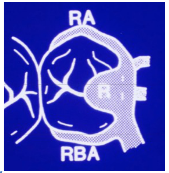
Direct Retainer And Clasp Assembly
The direct retainer or clasp assembly is categorized into two main types based on its relationship to the abutment tooth.
Extracoronal And Intracoronal Retainers
Extracoronal Retainers3
- More common, conventional “clasp” design.
- Clasps should encircle a tooth at least 180°. board-exam-question
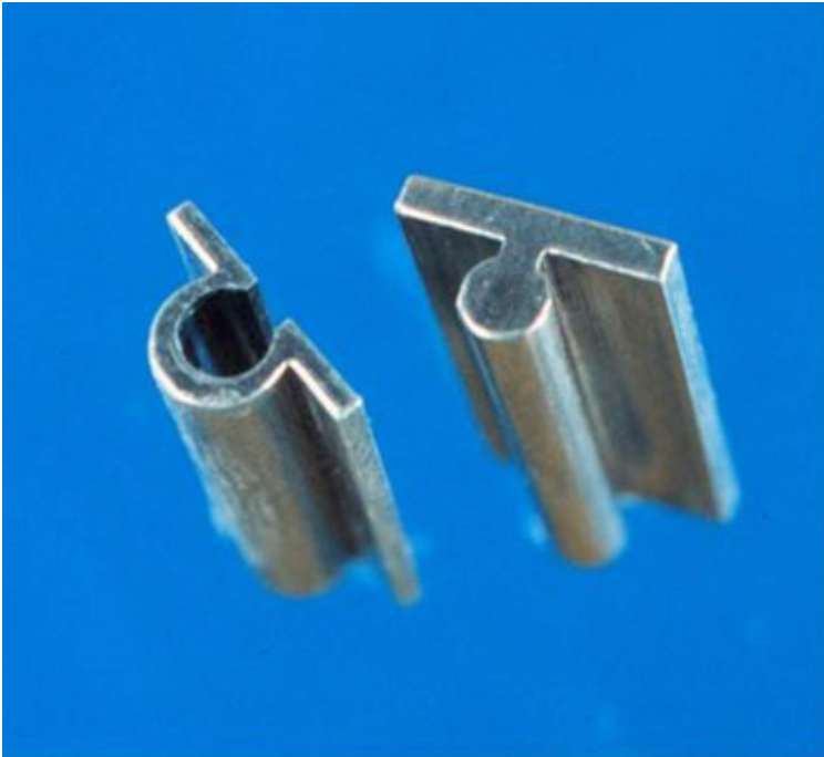
Intracoronal Retainers
- A precision attachment utilizing a key and keyway pattern.
- Offers improved esthetics due to the absence of visible clasps.
- Design: They require a "survey crown" on the abutment tooth, which has the female part (keyway) and rest seats built-in. The male part (key) is part of the partial framework.
Retentive Clasp Arm
Design and Function4
- Originates from the minor connector and rest.
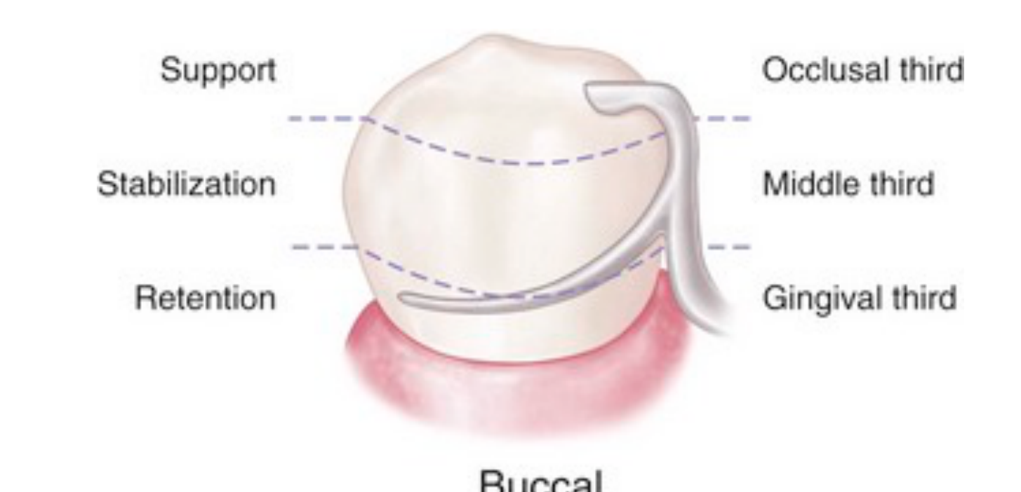
- Contacts tooth below the height of contour (HOC) or survey line.
- The shoulder and middle portions should be positioned above the HOC.
- Only the tip should be located under the HOC.
- The tip is designed to engage in the undercut to resist dislodging forces.
- The arm is only active when dislodging forces are applied; otherwise, it should seat passively.
- Tooth Contact: The tooth is divided into thirds. The occlusal third provides support, the middle third provides stability, and the gingival third provides retention.
- Location: Usually located on the buccal surface, though this may change if a tooth is tipped.
IF tooth is heavily tipped
then you might have to put the retentive clasp arm labial and the reciprocal arm labially
Reciprocal Clasp Arm
Design and Function5
- Also known as a stabilizing clasp.
- Originates from the minor connector and rest.
- Contacts the tooth above the height of contour (HOC) or survey line.
- Braces the abutment tooth to prevent it from being torqued by the retentive clasp arm.
- Placement: Every part of this clasp, including the tip, must stay above the height of contour (survey line). It does not engage undercuts.
- Location: It is typically located on the lingual surface.

Clasp Designs And Classifications6
Clasps are classified by their point of origin relative to the survey line:
Suprabulge Origin
Suprabulge clasps originate from the minor connector above the survey line and swing downwards.
- Suprabulge: Originate above the survey line.
- Circumferential (Akers)
- Ring
- Combination
- Embrasure
- Infrabulge: Originate below the survey line.
- I-bar
- T-bar
- Bar type
- Y type
Suprabulge Clasps
Circumferential Akers Clasp7
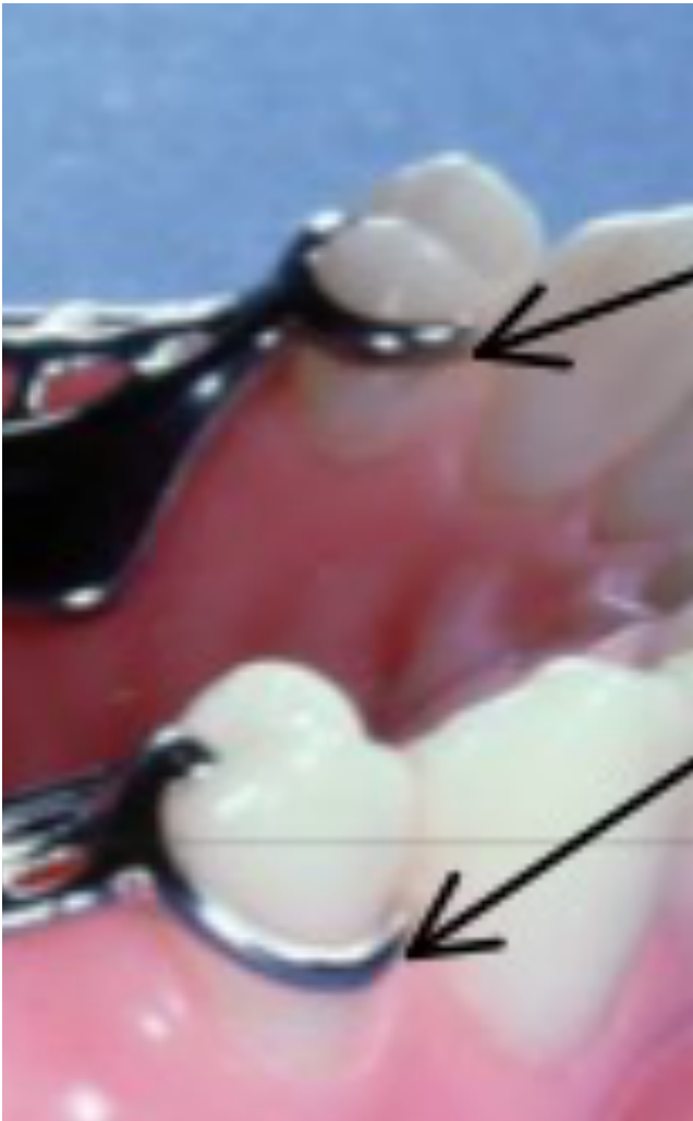
The Akers clasp is the only clasp in clinical orthodontics that circumscribes the abutment tooth on all of its facets.
- The most commonly used clasp design. board-exam-question
- Both the retentive and reciprocal arms originate above the survey line.
- It is highly versatile for various clinical scenarios. The clasp emerges from a guide plate and circumnavigates the entire tooth structure. This circumferential design grants exceptional retention when the prosthesis is in situ.
 |  |
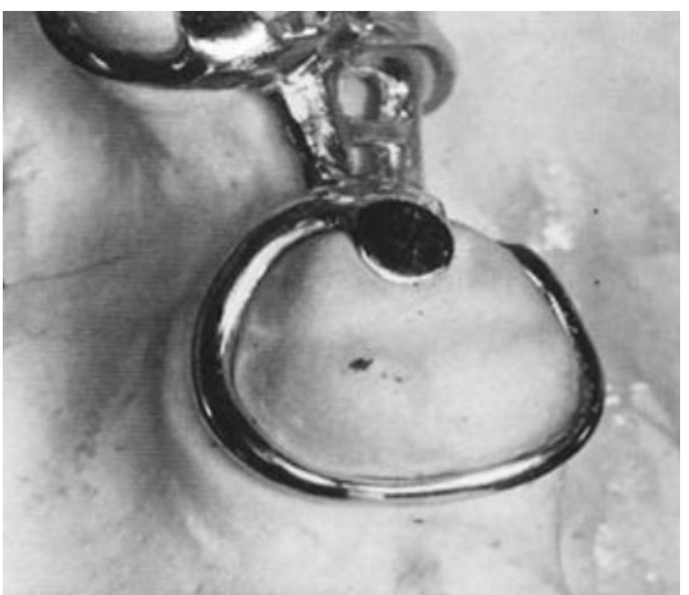
Ring Clasp8
Used when the undercut is adjacent to the Bound Edentulous Space (BES).
- Used when an undercut is adjacent to the bounded edentulous space (e.g., on the mesiofacial area of a molar).
- The clasp wraps around the entire tooth to reach the undercut.
- It may feature a second rest or an auxiliary arm for additional support.
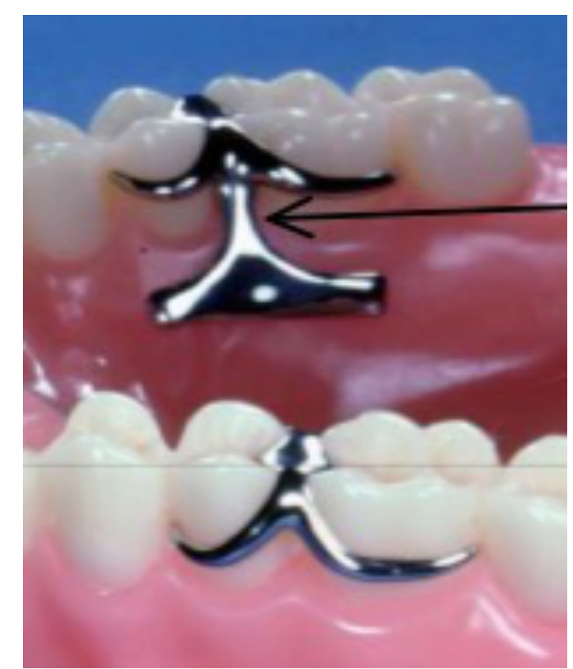
Embrasure Clasp9
- Essentially two Akers clasps joined together to encircle two adjacent teeth.
- Requires rests on both teeth to prevent the clasp from wedging the teeth apart or torquing them.
Infrabulge Clasps
Infrabulge Origin
These clasps originate from the framework meshwork below the survey line and rise to meet the retentive undercut.
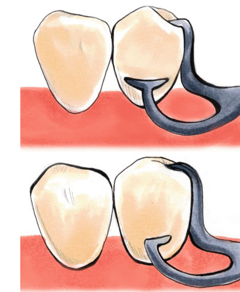
T-Bar Clasp10
- A bar-type design named for its "T" shape.
- Modified T-Bar (R-Bar): A variation of the T-bar named for its resemblance to a lowercase “r.”
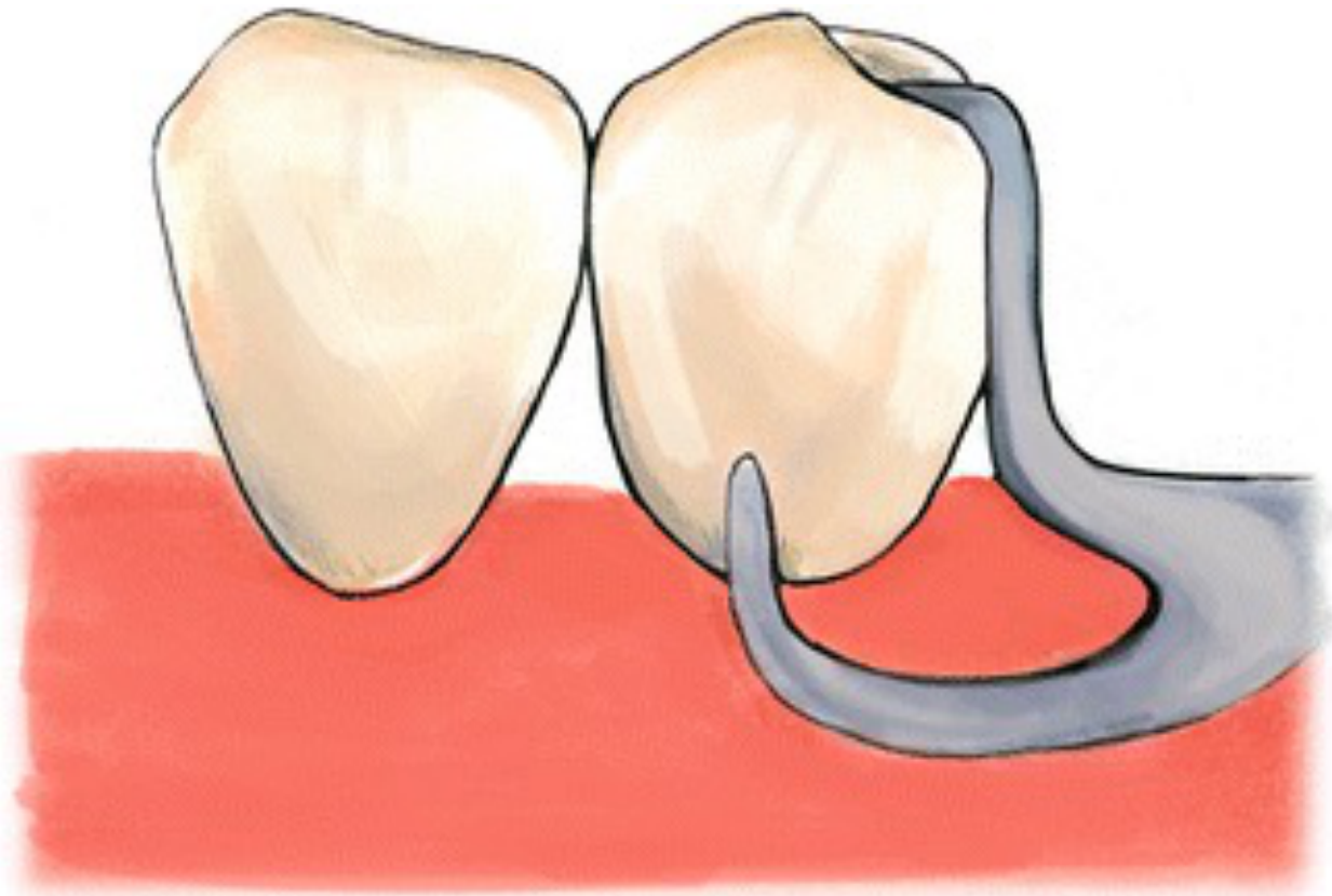
I-Bar Clasp11
I-Bar
- A straight-line design resembling the letter "I."
- Clinical Considerations: These require sufficient vestibular depth and cannot be used if there is a soft tissue undercut, as the clasp could become locked or cause trauma.
Clinical Application And Selection
Common Clasp Assemblies12
- RPI: Rest, proximal plate, I-bar (ideal Class II lever system).
- RPI: Rest (mesial), Proximal plate, and I-bar.
- RPA: Rest, proximal plate, Akers clasp.
- RPC: Rest, proximal plate, circumferential clasp (equivalent to RPA).
- RPC: Rest, Proximal plate, and Circumferential clasp (synonymous with Akers).

Criteria For Clasp Selection
Material and Case Considerations13
- Wrought wire: Used for periodontally compromised and endodontically treated teeth.
- Wrought Wire: A flexible clasp that is separately positioned and soldered to the framework. Because it is flexible, it puts less torque on the tooth.
- Bound Edentulous Space (BES): Use Akers clasps with rest seats located adjacent to the edentulous space.
- Distal extension: Use the following in order of preference:
- RPI
- RPA
- Wrought wire
Material Properties Of Cobalt-Chromium
Material Composition
Partial denture frameworks are typically made of cobalt-chromium alloy.
Physical Properties14
- 2.3% shrinkage: This inherent shrinkage causes irregularities and porosity in the casting.
- ==Strength: It is a very strong material.==
Cold-working
Definition
Also known as plastic deformation or work hardening, this occurs when the metal is manipulated at ambient temperature.
- Involves manipulating the metal while at ambient temperature.
- The clasp assembly is cold-worked every time it is seated and dislodged.
- This process is the main reason why clasps break. board-exam-question
Footnotes
-
Original PDF page 1: Prosthodontics - 13 - Clasp Design & Selection, p.1 ↩
-
Original PDF page 2: Prosthodontics - 13 - Clasp Design & Selection, p.2 ↩
-
Original PDF page 3: Prosthodontics - 13 - Clasp Design & Selection, p.3 ↩
-
Original PDF page 4: Prosthodontics - 13 - Clasp Design & Selection, p.4 ↩
-
Original PDF page 5: Prosthodontics - 13 - Clasp Design & Selection, p.5 ↩
-
Original PDF page 6: Prosthodontics - 13 - Clasp Design & Selection, p.6 ↩
-
Original PDF page 7: Prosthodontics - 13 - Clasp Design & Selection, p.7 ↩
-
Original PDF page 8: Prosthodontics - 13 - Clasp Design & Selection, p.8 ↩
-
Original PDF page 9: Prosthodontics - 13 - Clasp Design & Selection, p.9 ↩
-
Original PDF page 10: Prosthodontics - 13 - Clasp Design & Selection, p.10 ↩
-
Original PDF page 11: Prosthodontics - 13 - Clasp Design & Selection, p.11 ↩
-
Original PDF page 12: Prosthodontics - 13 - Clasp Design & Selection, p.12 ↩
-
Original PDF page 13: Prosthodontics - 13 - Clasp Design & Selection, p.13 ↩
-
Original PDF page 14: Prosthodontics - 13 - Clasp Design & Selection, p.14 ↩