Surveying Procedures12
Presented by Dr. Matsubara.
Introduction
This section covers the fundamental principles of survey and design in the context of Removable Partial Dentures (RPD).
Clinical Feedback and Self-Assessment
Prior to discussing surveying procedures, the lecturer emphasized the importance of self-assessment in clinical practice, particularly regarding temporary bridge fabrication. Students were advised to develop critical self-evaluation skills before presenting work to tutors, as exam conditions do not allow for iterative feedback. Key self-assessment points include:
- ==Margin integrity: Check for open margins before submission==
- ==Surface quality: Ensure temporary bridge surfaces are smooth to the touch==
- ==Clinical acceptability: Learn to identify errors (e.g., caries, soft decay) without tutor prompting==
This principle of self-assessment parallels the surveying process, where clinicians must visualize and plan modifications before executing them in the patient's mouth.
Learning Outcomes3
Upon completion of this section, students should be able to:
- Discuss the importance of study models.
- Discuss the importance of surveying for the fabrication of an RPD.
- Describe all steps of dental surveying.
- Define the position of rest/rest seat, undercuts, minor connectors, and major connectors.
- Describe the adjustment of the height of contour on abutment teeth.
Study Model4
The study model is constructed using Dental stone (Type III gypsum).
Material Selection
Use dental stone (Type III), not die stone, as Type III allows for cast trimming during surveying
Applications and Functions
- Analysis of models mounted on the articulator
Articulator Analysis Capabilities
Mounting models on an articulator facilitates assessment of prosthetic space and occlusal plane from multiple angles. Specific capabilities include:
- ==Prosthetic space calculation: Identify over-erupted molars and calculate required reduction (enameloplasty vs. crown placement)==
- ==Occlusal plane establishment: Visualize occlusal discrepancies to plan enameloplasty or full coverage restorations==
- ==Treatment planning: Simulate ideal treatment plans (e.g., survey crowns) before patient consultation==
- Fabrication of Interim Removable Partial Dentures (RPD)
Additional Applications
==Interim RPDs: For urgent tooth replacement, alginate impressions can be sent to the lab for temporary acrylic appliances (though these lack the detail of properly prepared cases)==
- ==Essex retainers: Fabricated on study models for single-tooth replacement==
- ==Custom trays: Surveying helps determine tray extension and border seal==
- Surveying for the design of the RPD framework
- Duplication: Take two alginate impressions or duplicate the study model—one for custom tray fabrication and one for surveying
- Fabrication of custom trays
Surveying Process
Aims5
The primary objectives of the surveying process include:
- Defining the shape, form, and contours of teeth and associated structures that influence the RPD design.
- Identifying necessary modifications of dental structures to optimize the RPD design.
- Facilitating the selection of a Path of Insertion that is most compatible with:
- Aesthetic requirements
- Guiding plane location
- Retention (specifically the location and depth of undercuts)
- Hard and soft tissue interferences
- Prioritizes function over aesthetics when compromises are necessary
Steps6
The surveying process follows a systematic sequence:
- Preliminary visual assessment
- Determination of the path of insertion
- Marking the height of contour of teeth to identify retentive areas
- Defining the position of rest
- Identifying the desired undercut
- Drawing the outline of the framework
- Adjusting the height of contour and creating guiding planes
Step 1: Preliminary Visual Assessment78910
The clinician performs an initial visual assessment by viewing the cast from an occlusal perspective (from above) to determine the following foundational design elements:
- Kennedy Classification: Identification of the partially edentulous arch configuration.
- Fulcrum Line(s): Determination of the axis of rotation for the prosthesis.
- Potential Rest Seat Locations: Initial identification of teeth suitable for supporting the denture.
- Indirect Retention: Assessment of the need for components to prevent displacement of the denture base away from the tissues.
- Tooth assessment: Evaluate mesially tilted teeth, conical shapes (poor for retention), and tilted molars
During the initial visual assessment from the occlusal view, the clinician should begin evaluating the relative parallelism of proximal tooth surfaces. This helps in identifying potential path-of-insertion requirements early in the design process.
The visual assessment from above allows the clinician to evaluate the relative parallelism of proximal tooth surfaces. This stage is critical for identifying significant clinical challenges, including:
- Gross problems relating to path-of-insertion interference.
- Unfavorable tooth or tissue contours.
- Significant undercuts that may affect the prosthesis design.
Documentation and Occlusal Analysis
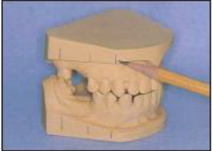
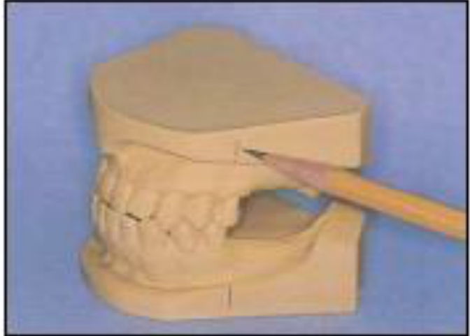
- Rest Seat Marking: Once potential rest seat locations are decided, they should be marked with vertical black lines on the cast bases for clear reference.
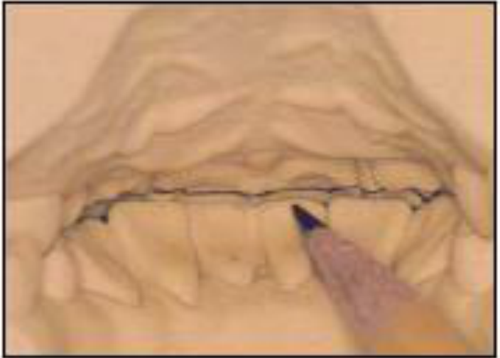
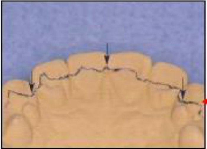
- Vertical Overlap: From the posterior aspect of the cast, assess and mark the vertical overlap of the teeth to understand the available inter-arch space.
Over-erupted Molar Management
When analyzing a mounted model with an over-erupted molar:
- The occlusal plane (following the Curve of Spee) should curve upward toward the posterior
- Minor over-eruption (≤1mm): Plan enameloplasty
- Significant over-eruption (>1mm or dentin exposure): Plan full coverage crown (survey crown) to seal dentin and establish proper occlusal plane
- This planning occurs entirely on the study model before patient treatment
Survey Crowns are crowns specifically designed to receive RPD components, featuring:
- Pre-designed rest seats
- Guide planes
- Correct undercut positioning
- Require additional occlusal reduction during tooth preparation to accommodate rest seat metal thickness
- Hand-articulate models to check occlusion and identify interference points for framework placement
Step 2: Path of Insertion
Maxillary Reference Points
To establish the path of insertion for the maxilla using the Roach technique, identify and utilize the following three points of contact:
Roach Technique1112
- Contact point between teeth 11 and 21 (central incisors)
- Marginal ridges of the molars
Surveyor Alignment
The initial orientation for the Roach technique requires the occlusal table to be positioned parallel to the base of the surveyor.
Class IV Cases
When no anterior teeth are present, use four points—two premolars on each side to establish the occlusal plane.
Mandible1314
Mandibular Reference Points (Incisors)
When applying the three-point Roach technique to the mandible, the following landmarks are used to determine the orientation:
- Incisal edges of the incisors
- Marginal ridges of the molars
Mandibular Reference Points (Posterior)
Additional landmarks for establishing the mandibular path of insertion include:
- Mesial marginal ridges of the premolars
- Marginal ridges of the molars
Reference with Wax15
Establishing the Wax Reference
Once the three points have been determined according to the Roach technique, create the physical reference on the cast using wax.
Unilateral Edentulous Technique
When anatomical references are missing on one side:
- Construct a wax block on the edentulous ridge at the height of the contralateral tooth
- Use this to establish the occlusal plane and path of insertion
- Remove the wax block after surveying; it is not part of the final RPD
Path Modification Principles
- The ideal path places clasps in the cervical area for aesthetics
- Tilt the cast to avoid soft tissue undercuts or bony interferences
- ==Caution: Do not create “false undercuts” by excessive tilting—if a tooth is conical or converges buccolingually, tilting cannot create true retention==
Mandibular Tori Management
- Option 1: Change path of insertion (tilt cast forward from posterior to anterior) to avoid the torus
- Option 2: Use alternative major connector designs (lingual plate instead of lingual bar; or Kennedy continuous clasp around cingulum)
- Option 3: Pre-prosthetic surgery (last resort when other options fail)
Palatal Torus (Maxilla)
- Avoid crossing the torus with the major connector
- Use horseshoe-shaped major connectors or position the strap posteriorly
Step 3: Height of Contour
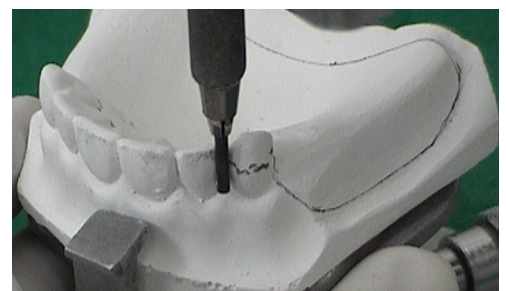
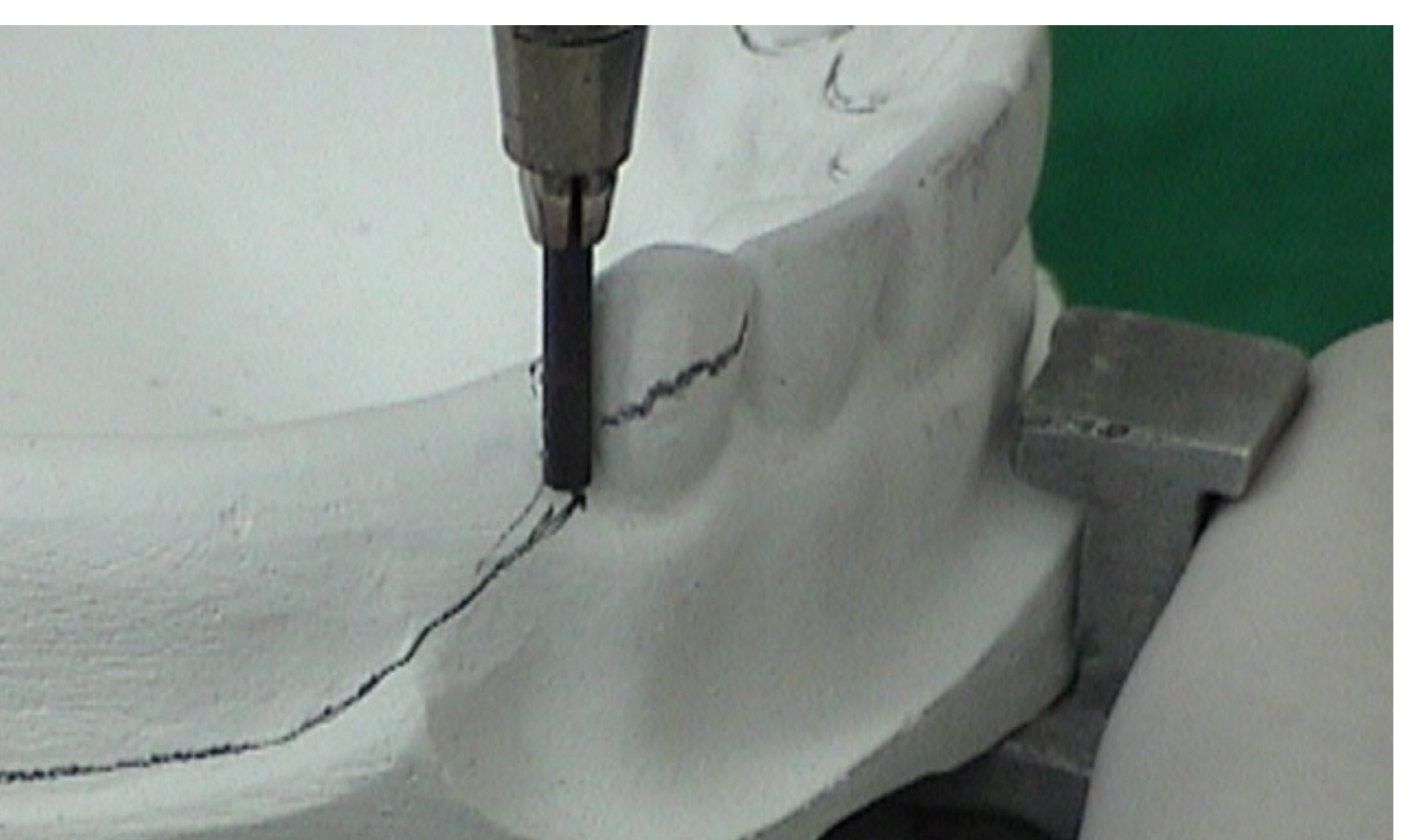
The survey lines are marked on the supporting teeth to identify the height of contour relative to the chosen path of insertion.
The height of contour (survey line) determines the division between retentive and non-retentive areas and influences clasp placement.
- Marked using the side (not tip) of a carbon marker
- Represents the greatest convexity of the tooth surface relative to the path of insertion
- Determines where the retentive arm tip (below) and reciprocal arm (above) will engage
Survey Lines of Supporting Teeth16
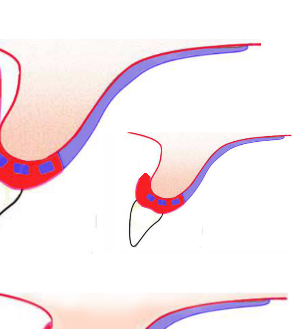
Survey Lines of Supporting Tissues171819
Impact on Retainer Selection
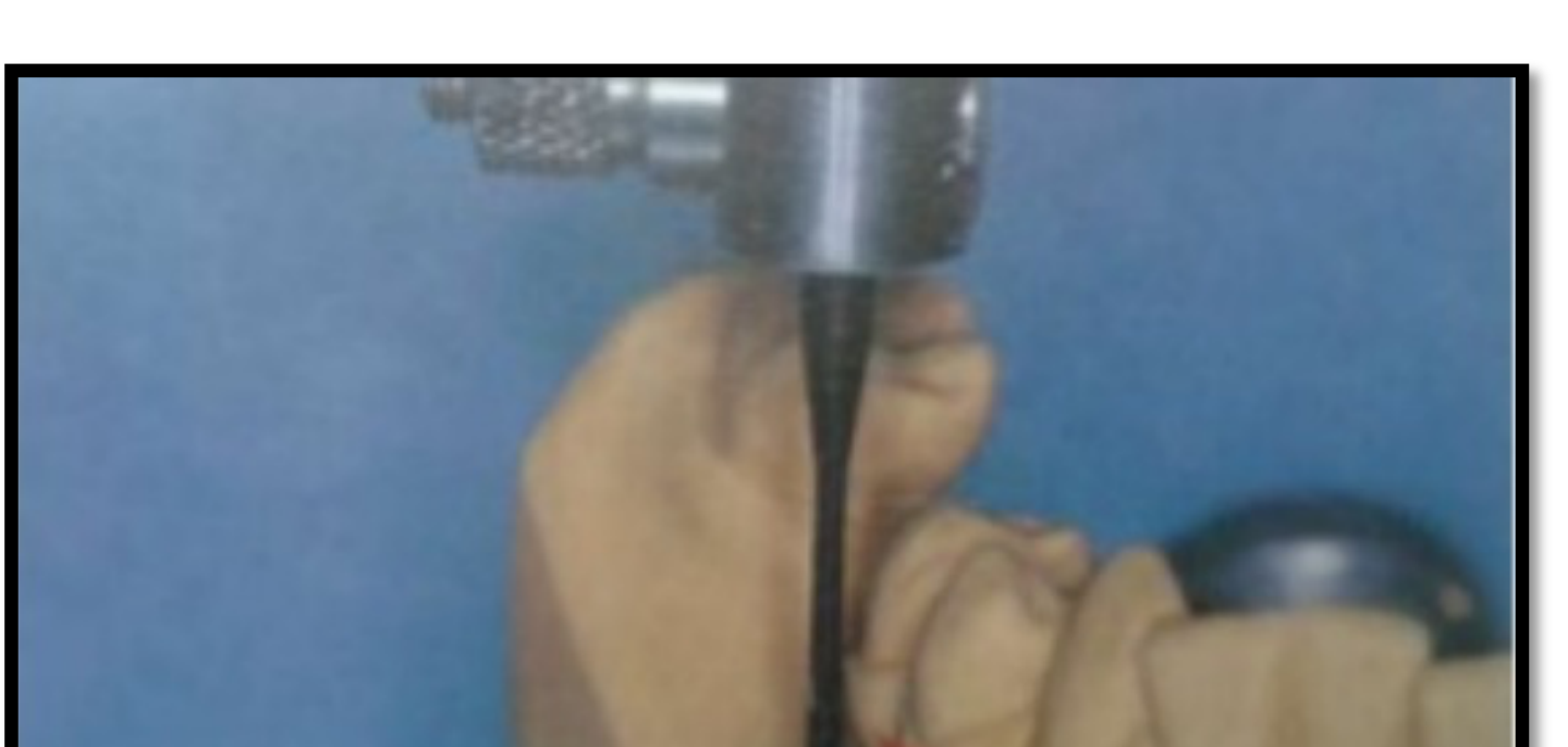
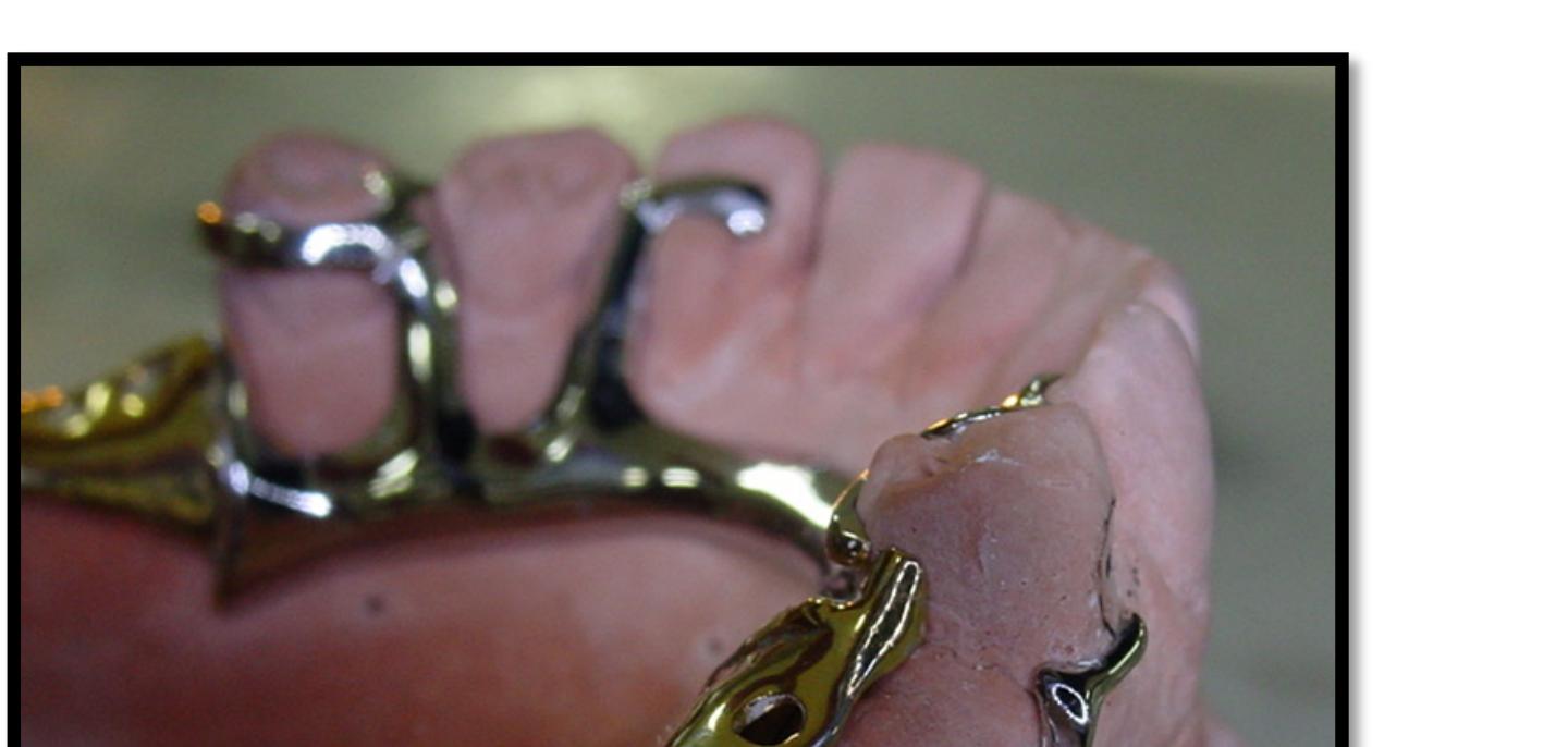
The extent of supporting tissue undercuts defines whether an infra-bulge retainer is a viable option for the prosthesis design.
- Evaluates the contour of edentulous ridges and soft tissue anatomy
- Determines denture flange extension and major connector placement
Requirements for Infra-bulge Retainers
To successfully utilize infra-bulge retainers, there should ideally be 3 mm of attached gingivae measured from the free gingival margin to the top of the tissue undercut.
The extent of supporting tissue undercuts is a critical factor in determining whether an infra-bulge retainer can be incorporated into the design.
The extent of supporting tissue undercuts defines whether an infra-bulge retainer is possible.
Soft Tissue Undercuts20
Soft tissue undercuts often involve bony protuberances that can interfere with the proper seating of the denture base or the major connector.
Soft Tissue Undercut Limitations
A 3mm limit exists for soft tissue undercuts:
- <3mm undercut: Use infrabulge clasps (I-bar, T-bar)
- >3mm undercut: Use suprabulge clasps to avoid tissue impingement
Implications of Improper Clasp Selection
- I-bars crossing gingival margins at oblique angles (rather than 90°) compromise biomechanics and periodontal health
- Relief areas may trap food or impinge on buccal mucosa
Management Strategies
If significant undercuts are present, the following actions may be considered:
- Change the Path of Insertion (POI) to bypass the interference.
- Utilize a major connector design specifically shaped to avoid the bulky tissue area.
- Perform pre-prosthetic surgery to reduce the bony protuberance.
Clinical Implications21
Functional and Aesthetic Challenges
Improper management of the height of contour and tissue undercuts can lead to food entrapment and significant aesthetic issues.
Role of the Buccal Flange
The buccal flange serves multiple purposes in the final design:
- Aids in overall aesthetics.
- Assists in the retention and stability of the Removable Partial Denture (RPD).
Flange Design Considerations (Class IV Cases)
- Lip support: Significant bone loss requires acrylic flange to support the lip
- Aesthetics: High smile lines reveal the alveolar ridge; the flange masks the transition between denture and soft tissue
- Retention and stability: The flange provides resistance to rotational movements and creates peripheral seal through suction
- Food impaction: Proper flange extension prevents food trapping
Applegate Technique22
The final path of placement is determined by the anteroposterior and lateral position of the cast in relation to the vertical arm of the surveyor. This position must best satisfy the following requirements:
- Retention
- Guiding planes
- Interference
- Esthetics
The Applegate technique is utilized as a convenience technique to achieve this optimal orientation.
Lateral Tilt23
The goal of lateral tilting is to ensure that reasonable retention is balanced effectively between all the abutment teeth.
- Tilts the cast buccolingually to equalize height of contour between abutment teeth
- Improves aesthetics by positioning clasps more cervically
- Balances undercut availability on bilateral abutments
Comparative Analysis
- Before Applegate technique: Initial assessment of lateral retention levels.
- After Applegate technique: Final balanced state where retention is distributed across the arch.
Anterior Posterior Tilt24
The objective of the anterior-posterior tilt is to establish adequate guiding planes while minimizing the removal of tooth structure.
Clinical Consideration
If ideal path requires excessive tooth reduction (exposing dentin), consider slight AP tilt for more conservative preparation or plan a survey crown
Limitation
Excessive AP tilt may create false undercuts that cannot be clinically utilized
Comparative Analysis
- Before Applegate technique: Evaluation of existing tooth contours and potential guiding plane locations.
- After Applegate technique: Optimized tilt that provides parallel surfaces with conservative tooth preparation.
Tripoding the Cast2526
Tripoding is a procedure that allows casts to be recorded and reproduced in the same pre-established orientation used during the framework design. This ensures the model can be placed back on the survey table accurately at any time.
Methods of Tripoding
- Horizontal Plane
- Vertical Plane
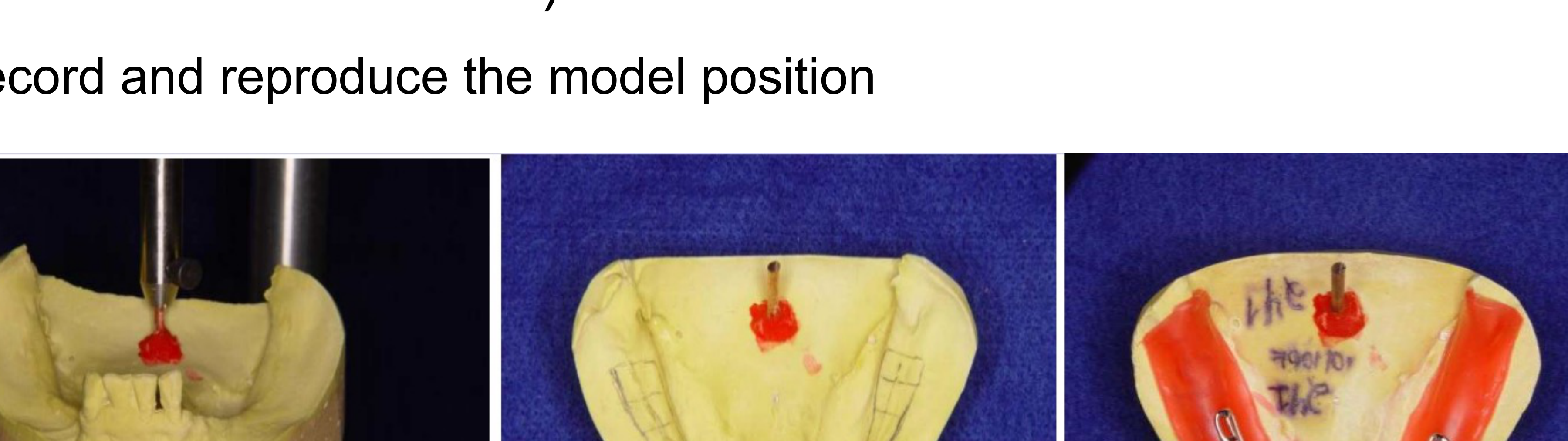
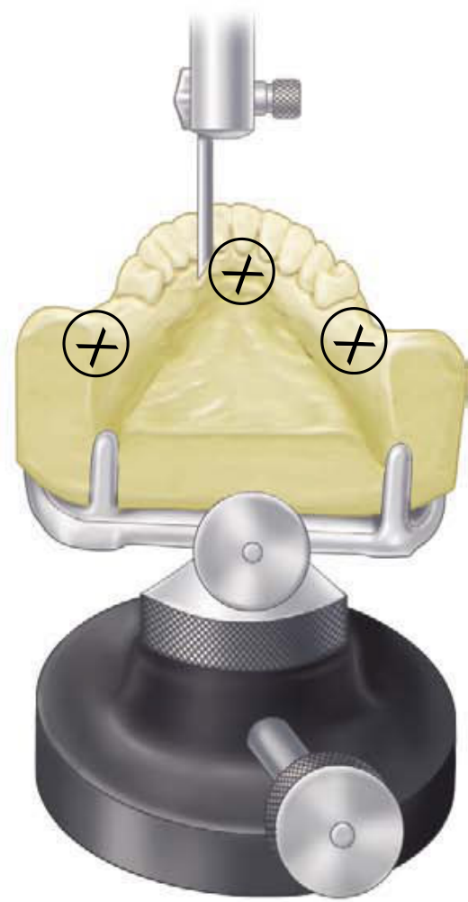
Horizontal Plane27
Procedure for Horizontal Tripoding
-
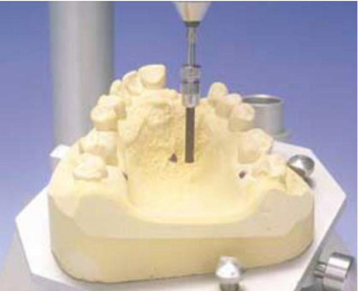
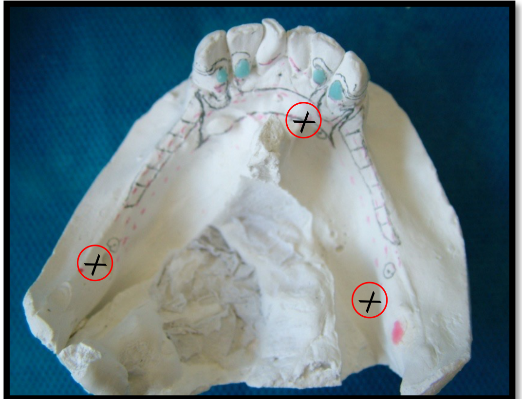
With the vertical arm of the surveyor locked, three wide-spread tissue points are selected in relatively non-critical areas.
-
Mark three points on areas of the cast that will not change (typically on the base or stable anatomical landmarks)
-
Advantage: Transferable to new models if reference points are carefully selected
-
These points are marked for future identification.
-
To reposition the cast, the survey table is maneuvered until all three marked points coincide with the fixed vertical arm.
Vertical Plane28
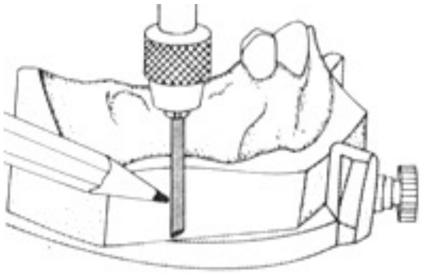
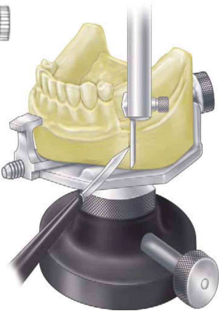
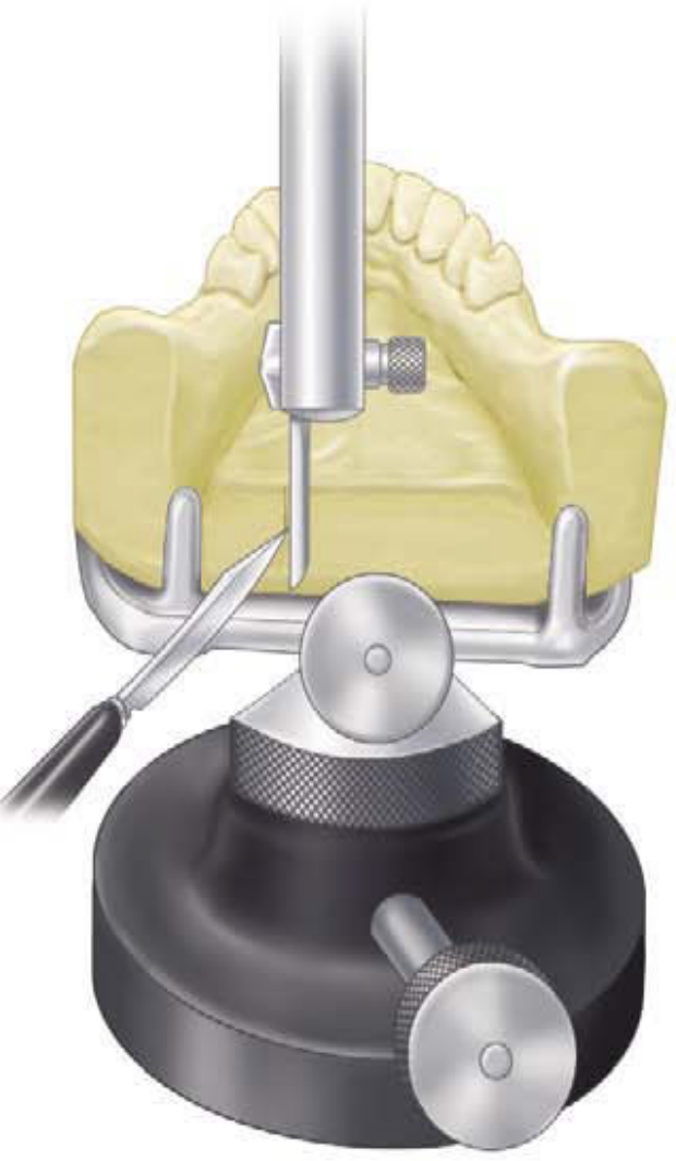
Procedure for Vertical Tripoding
- The analyzing rod is used as a guide ruler.
- Three parallel divergent markings are created on the dorsal side and the two lateral sides of the cast.
- These vertical lines are used to re-orientate the cast to the original plane by aligning them with the vertical arm of the surveyor.
Limitation
Not transferable to new models due to trimming variations between casts
Alternative
Fix the surveyor pin with Duralay resin to create a physical stop for repositioning
This process is essential for recording and reproducing the model position throughout the survey and design phases of the path of insertion.
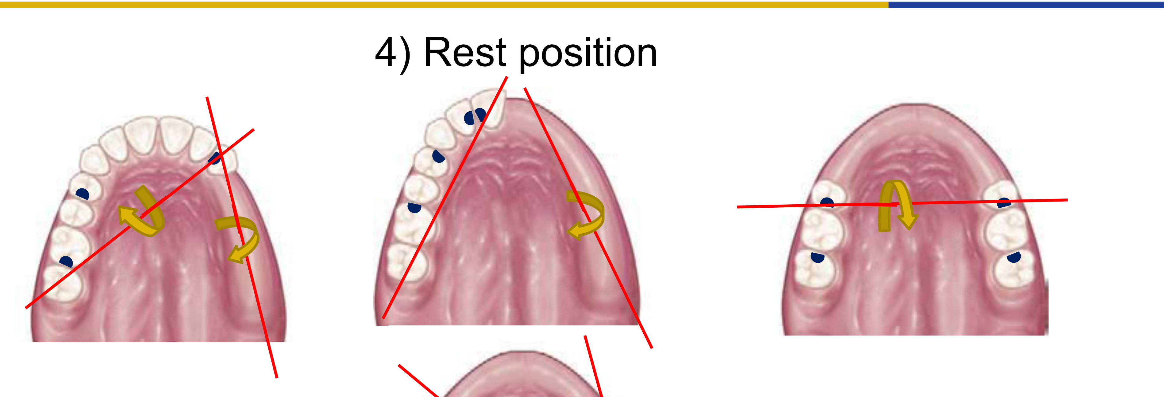
Step 4: Rest Position293031
Placement Guidelines for Rests
-
Intercalated Edentulous Area: The rest position should be located adjacent to the edentulous area.
- Follows the biomechanical principle of support nearest to the edentulous area.
-
Free-end Edentulous Area: The rest position should not be placed immediately adjacent to the saddle.
-
Rationale: Rests are placed distal to the edentulous space to prevent tissueward rotation of the denture base; mesial rests tend to open the distal gap under occlusal load
-
Indirect Retention Principles:
- Indirect retainers must be placed perpendicular to and away from the fulcrum line
- Fulcrum line: Axis of rotation through the most posterior rests on each side of the arch
- For bilateral distal extension (Class I), rests on canines or premolars anterior to the fulcrum line provide indirect retention
Visual Indicators of Rest Position
- Identification of the specific tooth surface designated for the rest.
- Integration of the rest within the dental crown architecture.
- Application of the rest position on molar teeth within a dental model.
Case Study: Class I Bilateral Distal Extension
- Fulcrum line: Connects the most posterior rests (typically mesial of first molars or distal of second premolars)
- Indirect retention: Place rests on canines or premolars anterior to the fulcrum line
- Biomechanics: When sticky food lifts the distal extension base, the anterior rests act as indirect retainers to prevent
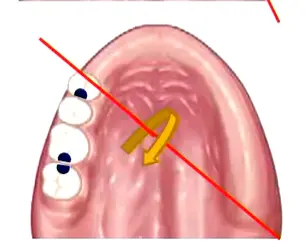
Case Study: Class II Unilateral Distal Extension
- Fulcrum line: Connects the rest on the distal extension side to the rest on the opposite side (often a molar)
- Indirect retention: Place rests on teeth anterior to the fulcrum line (canine or premolar on the distal extension side, or contralateral anterior teeth)
- Preference: Premolars preferred over canines in the maxilla to avoid interference with canine-guided lateral movements
Case Study: Anterior Free-End Saddle (Large Class IV)
- Functions biomechanically as an anterior free-end saddle
- Fulcrum line: Along the edentulous space
- Rest placement: Move rests distal to the space (posteriorly) to prevent anterior rotation
- Consider the high smile line when planning rests in the aesthetic zone
- Rest Position Selection:
- Mesial vs. Distal: Choose based on opposing tooth contact; if mesial surface has heavy contact and distal is free, use distal rest to minimize tooth reduction
- Ring Clasp application: For tilted molars where one side has no undercut, use a ring clasp engaging the mesial and distal surfaces with the retentive tip finishing on the side with the undercut
Step 5: Desired Undercut3233
Material Specifications
- Cobalt-Chromium (CoCr)
Undercut Identification and Clasp Selection
Undercut identification determines clasp selection and retention mechanics.
Undercut Gauges:
- ==Use the undercut gauge to identify 0.25mm undercut (standard for cobalt-chrome clasps)==
- ==Technique: Touch the gauge tip to the tooth surface below the height of contour, then move the shank upward until it contacts the tooth; mark this point==
- ==Only the terminal third of the retentive arm should engage the undercut==
Clasp Design Considerations:
- ==Reciprocal arms: Positioned above the height of contour, parallel to the tooth surface (not tapered)==
- ==Retentive arms: Tapered to provide flexibility in the terminal third; positioned below the height of contour==
- ==Buccal/Lingual placement: Standard placement places retention on the buccal and reciprocation on the lingual; however, if a tooth is tilted lingually, reverse the placement to utilize available undercuts==
Clasp Selection Based on Undercut:
- ==Simple Circlet: Used when undercut is available on the side opposite the rest==
- ==Reverse Circlet: Used when the undercut is adjacent to the rest (e.g., distal undercut with mesial rest)==
- ==Ring Clasp: Encircles the tooth to engage a lone undercut on a tilted molar==
- ==I-bar/T-bar: Infrabulge clasps for aesthetic zones; must cross the gingival margin at 90° to prevent periodontal compromise==
Modification Options:
- ==Adding composite: If undercut is insufficient, add composite to create retention rather than compromising biomechanics with poor clasp design==
- ==Changing design: Prefer design modifications over tooth addition when possible==
Step 6: Outline of Framework3435
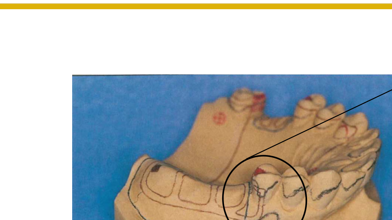
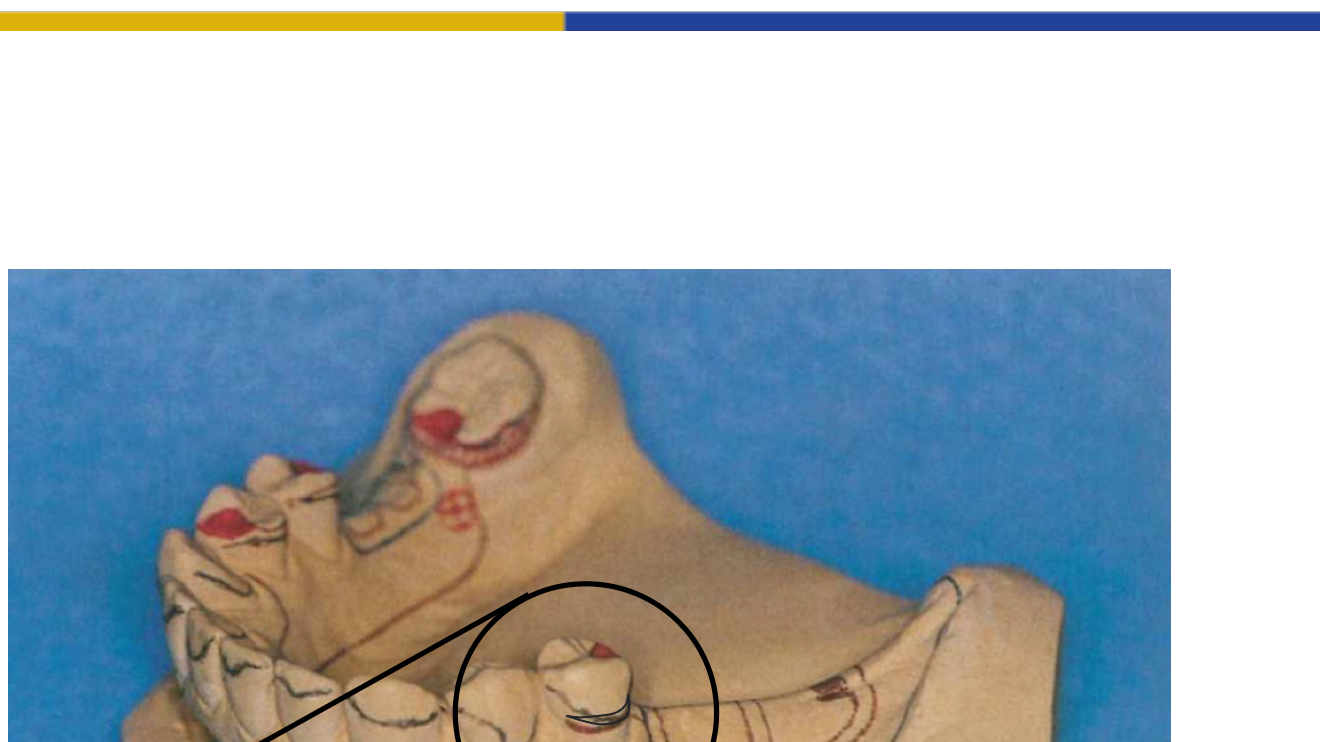
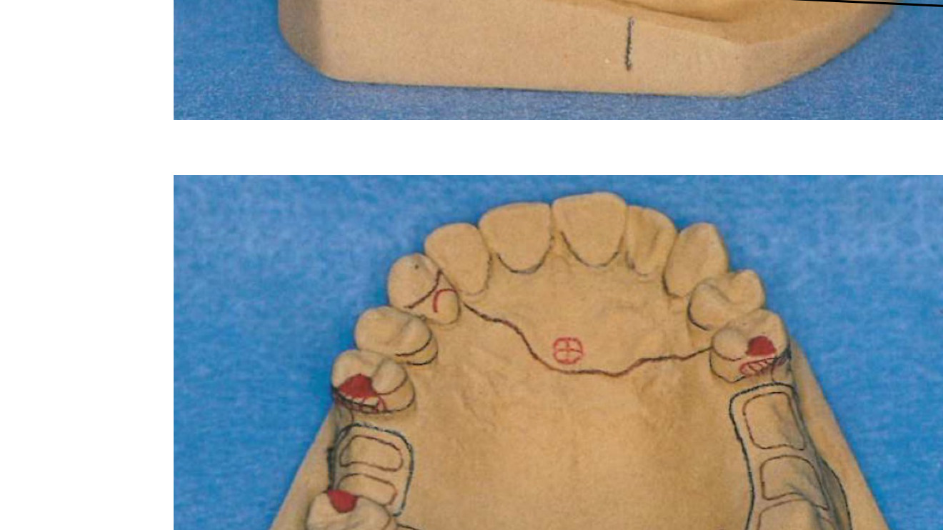
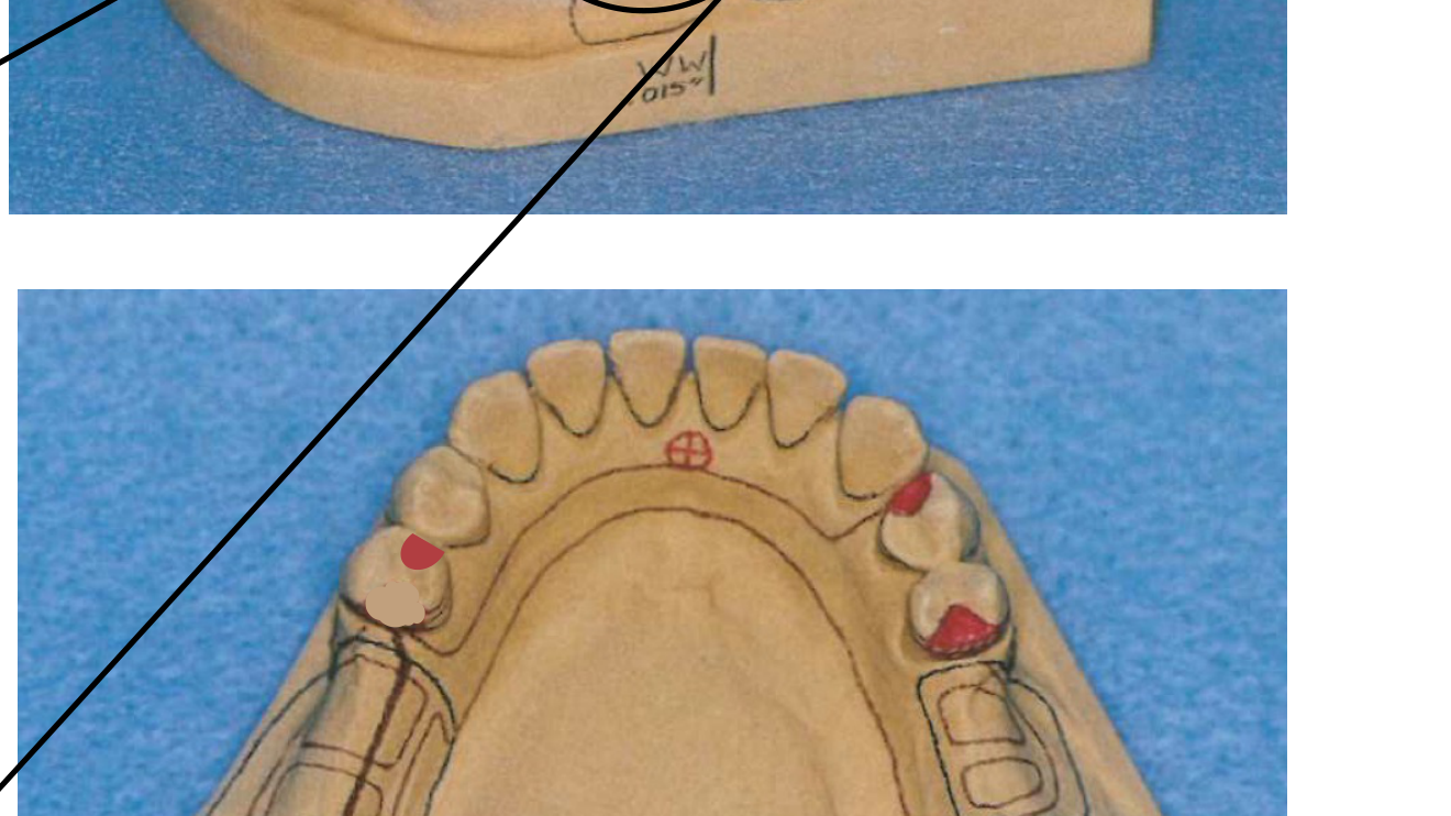
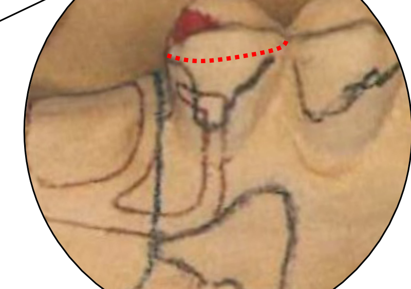
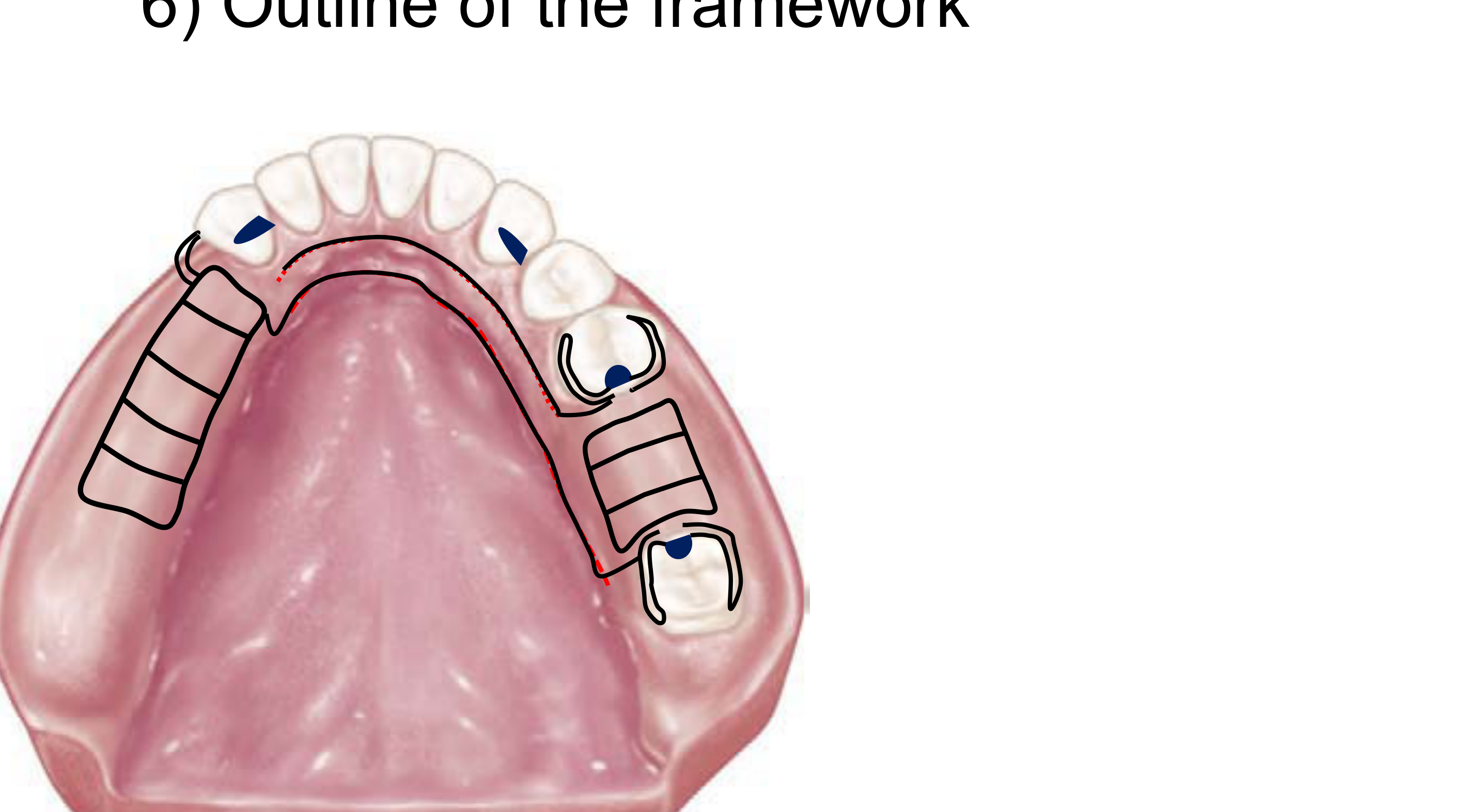
The initial steps in outlining the framework involve identifying the following elements:
- Rests: Location and preparation sites.
- Grid: Design of the denture base attachment area, typically covering 2/3 of the ridge.
Framework Components36
The framework outline includes the following primary components:
- Rests
- Grid
- Clasps: Including the retention arm (both supra-bulge and infra-bulge designs), reciprocating arm, and proximal plate.
Major Connector37383940
The framework design incorporates rests, grids, and various clasp assemblies (retention arms, reciprocating arms, and proximal plates) using supra-bulge and infra-bulge approaches.
Major Connector Design Specifications
Maxillary Connectors:
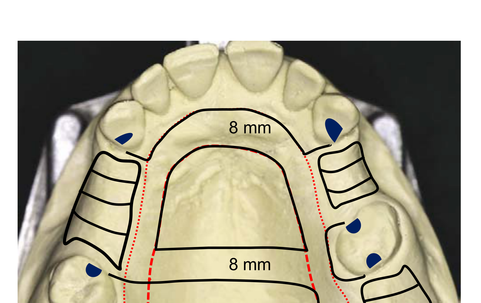
- ==Palatal Strap dimensions: Minimum 8mm width; position 6mm from the gingival margin (total 14mm space required: 6mm clearance + 8mm width)==
- ==Posterior limit: Place anterior to the vibrating line for patient comfort==
- ==Midline junction: Must meet at right angles (90°), never oblique angles==
Mandibular Connectors:
- ==Lingual Bar requirements: Requires minimum 8mm vertical space (3mm from gingival margin + 5mm bar height)==
- ==Lingual Plate indication: Alternative when <8mm vertical space exists; covers tooth surfaces and soft tissue without compromising rigidity==
- ==Width standards: Minimum 5mm for strength; wider and flat designs are preferred over narrow and thick for patient comfort==
Critical Design Rules:
- ==Universal 3mm rule: Maintain 3mm clearance from gingival margins for all major connectors==
- ==Tori management: Do not cross mandibular tori or palatal tori with the connector design==
Placement Specifications
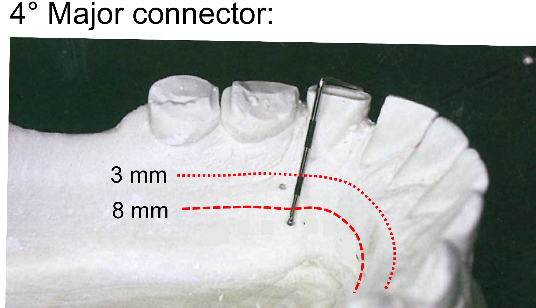
- Mandibular Major Connector: Positioned 3–4 mm away from the gingival margin and the floor of the mouth.
- Maxillary Major Connector: Positioned 5–6 mm away from the gingival margin; design must avoid the torus and the soft palate.
Connector Dimensions and Morphology
- Strap Design: Used when the width is 8 mm or greater. These can be designed thinner and flat.
- Bar Design: Used when the width is less than 8 mm. These require increased bulk for structural rigidity.
Clearance Requirements
- Mandibular Clearance: 3–4 mm from the gingival margin.
- Maxillary Clearance: 5 mm from the gingival margin.
Dimensional Standards for Framework Design
-
Mandibular Specifications:
- Minimum clearance from gingival margin: 3 mm.
- Minimum width of the major connector: 8 mm.
-
Maxillary Specifications:
- Minimum clearance from gingival margin: 6 mm.
- Standard strap width: 8 mm.
- Extended plate or wide strap width: 14 mm.
The outline of the framework continues with the specific configuration and placement of the major connector based on the anatomical requirements of the dental arch.
Minor Connector41
The framework outline is completed by integrating all structural elements:
- Rests
- Grid
- Clasps
- Major connector
- Minor connector
Finalization of the survey and design process for the framework outline.
Minor Connector Specifications
- ==Connection function: Joins the major connector to other components (clasps, rests, grids)==
- ==Gingival margin protocol: Should cross the gingival margin at right angles to minimize tissue trauma==
- ==Design balance: Provide rigidity while minimizing tissue coverage==
[!example] Grid and Saddle Design Protocol
- ==Free-end saddle coverage: Cover 2/3 of the edentulous ridge to distribute load and reduce tooth stress==
- ==Intercalated space clearance: Maintain 3mm clearance from the gingival margin==
- ==Tissue stops: Provide support for free-end saddles to prevent tissueward movement during function==
Measurement Technique:
- ==Perioprobe protocol: Use a perioprobe to mark 3mm from the gingival margin on the lingual side and 8mm (or 6mm for maxilla) for major connector placement==
- ==Drawing guides: Draw dotted lines to guide framework drawing on the cast==
Step 7: Adjust Height of Contour and Guiding Planes
The primary objectives when adjusting the height of contour are to ensure proper placement of the clasp assembly components:
The final step simulates clinical tooth modification on the cast.
Aim42
- Reciprocating Arm Placement: Ensure the entire reciprocating arm is positioned above the height of contour.
- Retention Arm Placement: Position the terminal third (1/3) of the retention arm within the designated undercut.
- Optimize clasp mechanics by positioning the height of contour to allow the reciprocal arm above and retentive terminal third below
- Create parallel guiding planes for path of insertion control
- Minimize food impaction and improve denture stability
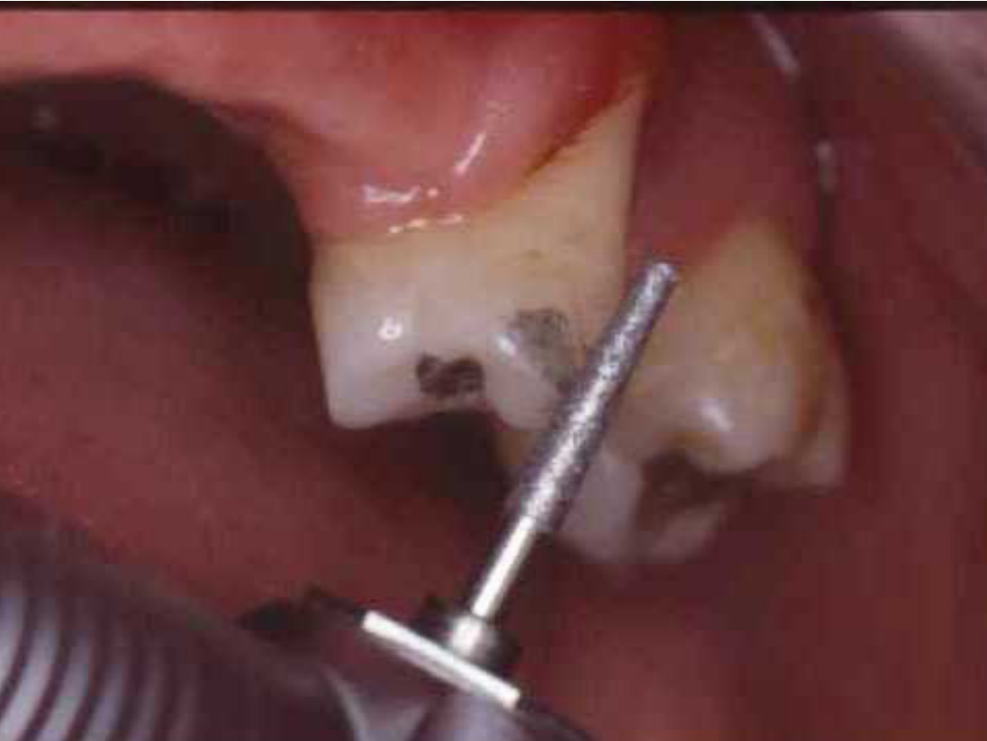
Modifying Height of Contour434445
Utilization of Surveying Tools
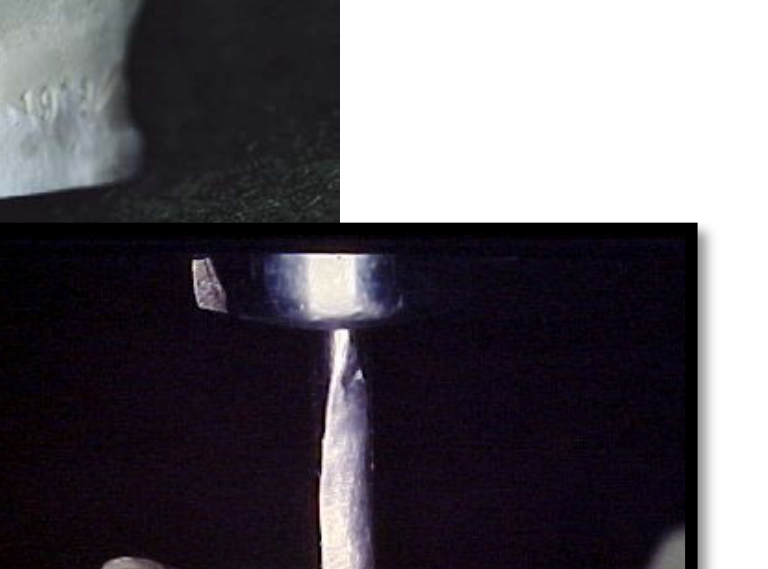
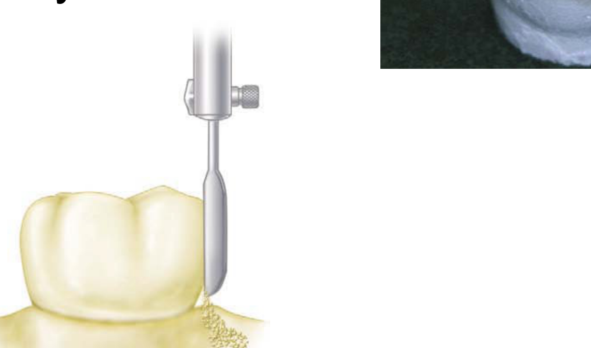
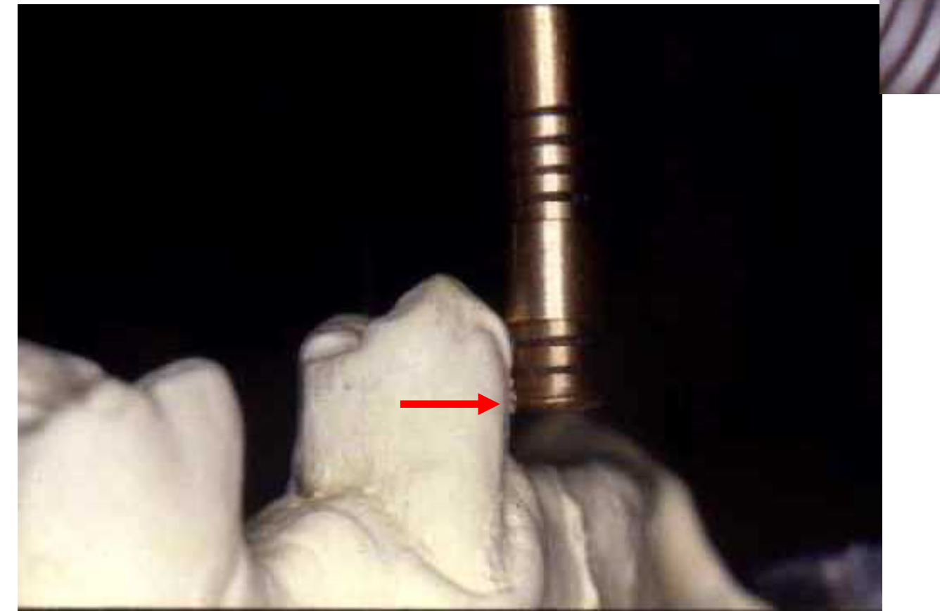
- Surveyor Blade: Use the surveyor blade to identify areas where the height of contour requires modification to facilitate proper clasp positioning and function.
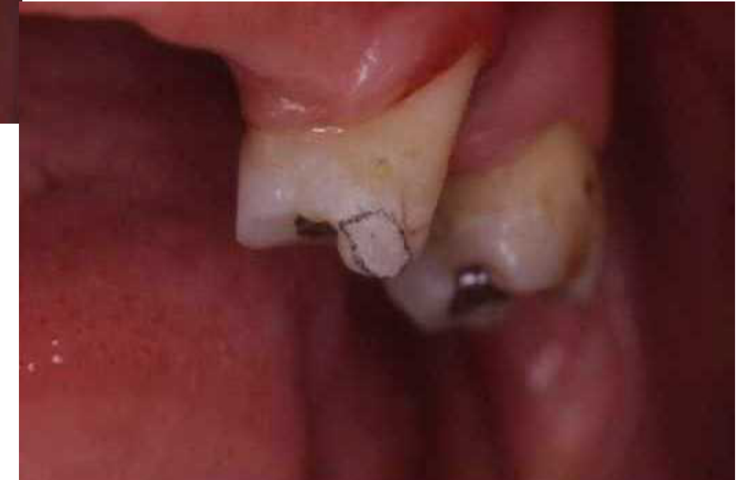
The height of contour is modified to re-establish the survey line at a more favorable position for the prosthetic components.
Adjustments to the height of contour are performed to ensure that the rigid components of the partial denture do not encounter interference during insertion and removal.
Simulation on Cast
Use trimming instruments to reduce tooth contour on the cast where the height of contour is too high
Clinical Application If the height of contour is at the occlusal third, trim the buccal surface to lower the survey line to the middle third, allowing the clasp arm to originate from the occlusal while keeping the terminal third in the undercut
[!info] Clinical Transfer
Transfer the simulated modifications to the mouth using high-speed burs. Reduce the buccal or proximal surfaces to lower the height of contour.
==Result: The height of contour becomes a plane rather than a line, allowing the clasp to engage properly without showing excessive metal.==
[!tip] Aesthetic and Functional Outcomes
- Lowering the height of contour improves aesthetics by positioning the clasp more cervically
- Prevents occlusal interference with the framework
- Maintains biomechanical advantage (retention below, reciprocation above)
Guiding Planes46
Purpose and Effects of Guiding Planes
-
Tooth Preparation: The natural bulge of the tooth must be flattened through selective preparation to create parallel surfaces.
-
Path of Insertion: These planes provide a single, predictable path of insertion (POI) for the Removable Partial Denture (RPD).
-
Stability: Limits the instability and lateral movement of the RPD during function.
-
Hygiene: Helps reduce food impaction between the prosthesis and the natural teeth.
-
Clinical Consideration: Care must be taken during preparation to avoid excessive dentine exposure
-
==Preparation Standards: Create flat surfaces on proximal areas to provide a single path of insertion==
- ==Guiding planes should extend 2/3 of the intercuspal distance (occlusogingivally)==
- ==Must encompass at least 2/3 of the clinical crown height==
- ==Consequence of insufficient reduction: Inadequate guiding planes result in poor denture stability and increased food impaction==
-
==Clinical Technique: Trim the cast to simulate the guiding plane preparation==
- Ensure the surface is flat and parallel to the path of insertion
- Verify that the proximal plate will have sufficient surface area for stability .
Clasp Body and Proximal Plate47
Component Dimensions and Positioning
-
Clasp Body: Designed in conjunction with the proximal plate to ensure structural integrity.
-
Proximal Plate:
- Should extend to approximately 2/3 of the intercuspal distance.
- Should cover approximately 2/3 of the crown height to provide adequate bracing and guidance.
-
==Integration: The clasp body and proximal plate work together to provide stability and retention. The proximal plate engages the guiding plane, while the clasp body provides reciprocation==
-
==Space requirements: Ensure sufficient reduction to accommodate both components without overcontouring==
Final Verification
- After all modifications, re-survey the cast to verify the path of insertion
- Confirm that undercuts are genuine and not artifacts of the trimming process
- Ensure the framework outline does not interfere with soft tissue or occlusion
Pre-prosthetic Surgery Indications
- When bony undercuts or tori cannot be avoided by path modification or design changes
- When soft tissue undercuts exceed 3mm and infrabulge clasps are contraindicated
- When ridge hyperplasia or other soft tissue anomalies prevent proper denture seating
The following procedures outline the systematic approach required for conducting accurate and reliable surveys. Adherence to these steps ensures data integrity and consistency across different project sites.
Pre-Survey Preparation
- Review all existing site documentation, including previous survey data, maps, and legal descriptions.
- Calibrate all surveying instruments, including total stations, GNSS receivers, and leveling equipment, to ensure they meet manufacturer specifications.
- Establish a clear project scope and identify specific control points required for the site.
Field Data Collection
- Control Point Establishment: Set up primary and secondary control points using permanent or semi-permanent markers. Ensure these points are tied into the national or local coordinate system.
- Topographic Mapping: Capture natural and man-made features, including elevation changes, vegetation, structures, and utilities.
- Boundary Determination: Locate and verify existing property corners and boundary lines based on recorded deeds and physical evidence found on-site.
Data Verification and Quality Control
- Perform redundant measurements on critical points to minimize the risk of human or instrumental error.
- Conduct real-time data validation in the field to identify any discrepancies before leaving the site.
- Document all environmental conditions (e.g., weather, temperature) that may impact the accuracy of electronic distance measurements (EDM).
Post-Processing and Reporting
- Download and process field data using approved surveying software.
- Compare field results against historical data to identify significant shifts or anomalies.
- Generate final deliverables, including topographic maps, boundary surveys, and digital terrain models (DTMs), ensuring all symbols and notations follow industry standards.
Footnotes
-
Original PDF page 1: L7 Survey and Design, p.1 ↩
-
Original PDF page 47: L7 Survey and Design, p.47 ↩
-
Original PDF page 2: L7 Survey and Design, p.2 ↩
-
Original PDF page 3: L7 Survey and Design, p.3 ↩
-
Original PDF page 4: L7 Survey and Design, p.4 ↩
-
Original PDF page 5: L7 Survey and Design, p.5 ↩
-
Original PDF page 6: L7 Survey and Design, p.6 ↩
-
Original PDF page 7: L7 Survey and Design, p.7 ↩
-
Original PDF page 8: L7 Survey and Design, p.8 ↩
-
Original PDF page 9: L7 Survey and Design, p.9 ↩
-
Original PDF page 10: L7 Survey and Design, p.10 ↩
-
Original PDF page 11: L7 Survey and Design, p.11 ↩
-
Original PDF page 12: L7 Survey and Design, p.12 ↩
-
Original PDF page 13: L7 Survey and Design, p.13 ↩
-
Original PDF page 14: L7 Survey and Design, p.14 ↩
-
Original PDF page 15: L7 Survey and Design, p.15 ↩
-
Original PDF page 16: L7 Survey and Design, p.16 ↩
-
Original PDF page 17: L7 Survey and Design, p.17 ↩
-
Original PDF page 18: L7 Survey and Design, p.18 ↩
-
Original PDF page 19: L7 Survey and Design, p.19 ↩
-
Original PDF page 20: L7 Survey and Design, p.20 ↩
-
Original PDF page 21: L7 Survey and Design, p.21 ↩
-
Original PDF page 22: L7 Survey and Design, p.22 ↩
-
Original PDF page 23: L7 Survey and Design, p.23 ↩
-
Original PDF page 24: L7 Survey and Design, p.24 ↩
-
Original PDF page 27: L7 Survey and Design, p.27 ↩
-
Original PDF page 25: L7 Survey and Design, p.25 ↩
-
Original PDF page 26: L7 Survey and Design, p.26 ↩
-
Original PDF page 28: L7 Survey and Design, p.28 ↩
-
Original PDF page 29: L7 Survey and Design, p.29 ↩
-
Original PDF page 30: L7 Survey and Design, p.30 ↩
-
Original PDF page 31: L7 Survey and Design, p.31 ↩
-
Original PDF page 32: L7 Survey and Design, p.32 ↩
-
Original PDF page 33: L7 Survey and Design, p.33 ↩
-
Original PDF page 40: L7 Survey and Design, p.40 ↩
-
Original PDF page 34: L7 Survey and Design, p.34 ↩
-
Original PDF page 35: L7 Survey and Design, p.35 ↩
-
Original PDF page 36: L7 Survey and Design, p.36 ↩
-
Original PDF page 37: L7 Survey and Design, p.37 ↩
-
Original PDF page 38: L7 Survey and Design, p.38 ↩
-
Original PDF page 39: L7 Survey and Design, p.39 ↩
-
Original PDF page 41: L7 Survey and Design, p.41 ↩
-
Original PDF page 42: L7 Survey and Design, p.42 ↩
-
Original PDF page 43: L7 Survey and Design, p.43 ↩
-
Original PDF page 44: L7 Survey and Design, p.44 ↩
-
Original PDF page 45: L7 Survey and Design, p.45 ↩
-
Original PDF page 46: L7 Survey and Design, p.46 ↩