Project 4: Kennedy Class 3 Modification 1 Partial Denture Design
1. Overview of Case Specifications
Project 4 focuses on a Kennedy Class 3, Modification 1 partial denture
 . This is a tooth-borne appliance. Unlike Class 1 or Class 2 cases, there are no rotation lines or dislodgement issues under function.
Key Characteristics:
- Support: Predominantly tooth-borne, though supported by the palate and ridges.
- Abutment Teeth: Always the teeth adjacent to the edentulous areas
 . In this case: 16, 13, 23, and 27.
- Indirect Retention: Generally not required for Class 3; however, plating/apron rests are incorporated here to prepare for potential future transitions to a Class 1 or 2 status.
- Aesthetic Considerations: The anterior section (canines) is in the “smile zone,” requiring low-profile clasping.
2. Clinical Assessment and Preparation
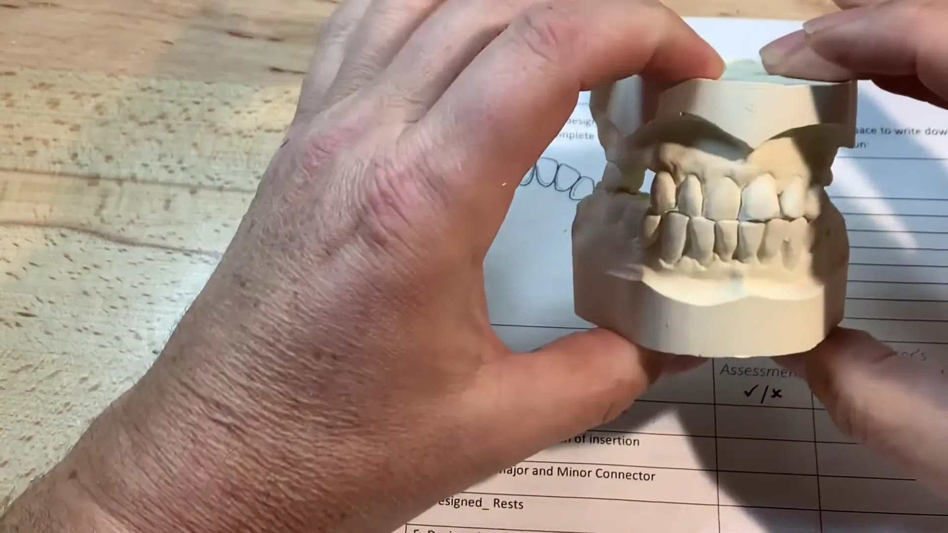
Before finalizing the design, the models must be articulated to check for occlusal clearance
 .
.
- Occlusion: The midlines are aligned. Quadrant 1 shows an end-to-end relationship, while Quadrant 2 is slightly open. Tooth 3 is in a Class 1 relationship.
- Rest Preparations: The dentist has prepared mesio-occlusal rests on the molars. It is critical that the metal framework does not exceed the height of these preparations
 to avoid occlusal interference.
- Surveying: The model is surveyed at a 0-degree position
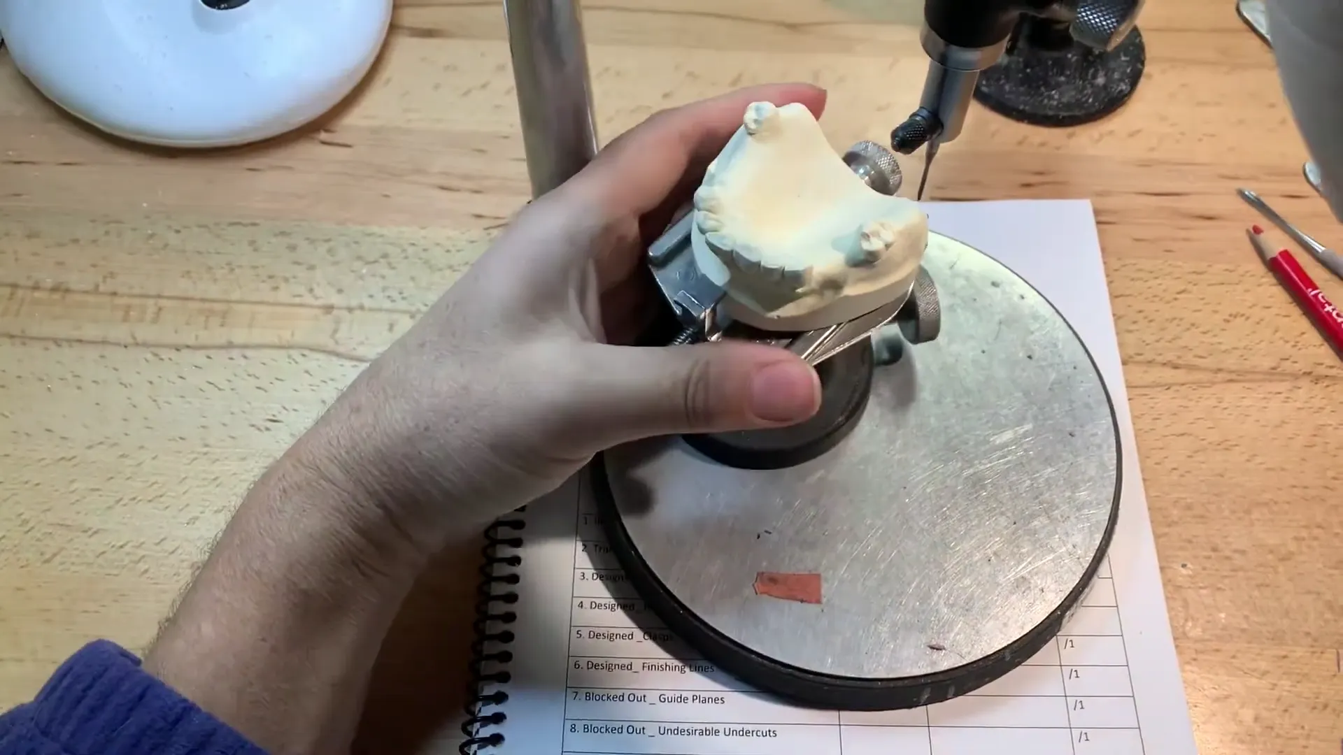 (parallel to the plane of occlusion). Guide planes are equalized to minimize spaces adjacent to the clasps.
3. Design Steps and Components
Step 1: Outline Edentulous Areas and Retention
- Areas: Teeth 14, 15 (Quadrant 1) and 24, 25, 26 (Quadrant 2).
- Framework Attachment: Use mesh lattice retention with a non-straight external finishing line
 .
.
Step 2: Identify Direct Retainers
| Tooth | Rest Location | Clasp Type | Undercut Engagement |
|---|---|---|---|
| 16 (Molar) | Mesio-occlusal | Akers Clasp | 0.25mm (Distal-buccal) |
| 27 (Molar) | Mesio-occlusal | Akers Clasp | 0.25mm (Distal-buccal) |
| 13 (Canine) | Cingulum/Apron | Wrought Wire | 0.75mm (Mesial-labial) |
| 23 (Canine) | Cingulum/Apron | Wrought Wire | 0.75mm (Mesial-labial) |
Note: Wrought wire is used on the canines to engage deeper undercuts (2/3 below the height of contour) while remaining low for aesthetics.
Step 3: Major Connector
- Type: Palatal strap verging on a horseshoe design.
- Placement: Crosses the midline at 90 degrees
 . It should be kept 3–5mm below the incisive papilla
 and avoid crossing major rugae where possible.
- Width: Roughly corresponds to the width of the posterior teeth being replaced.
4. Laboratory Procedures
Tripoding the Model
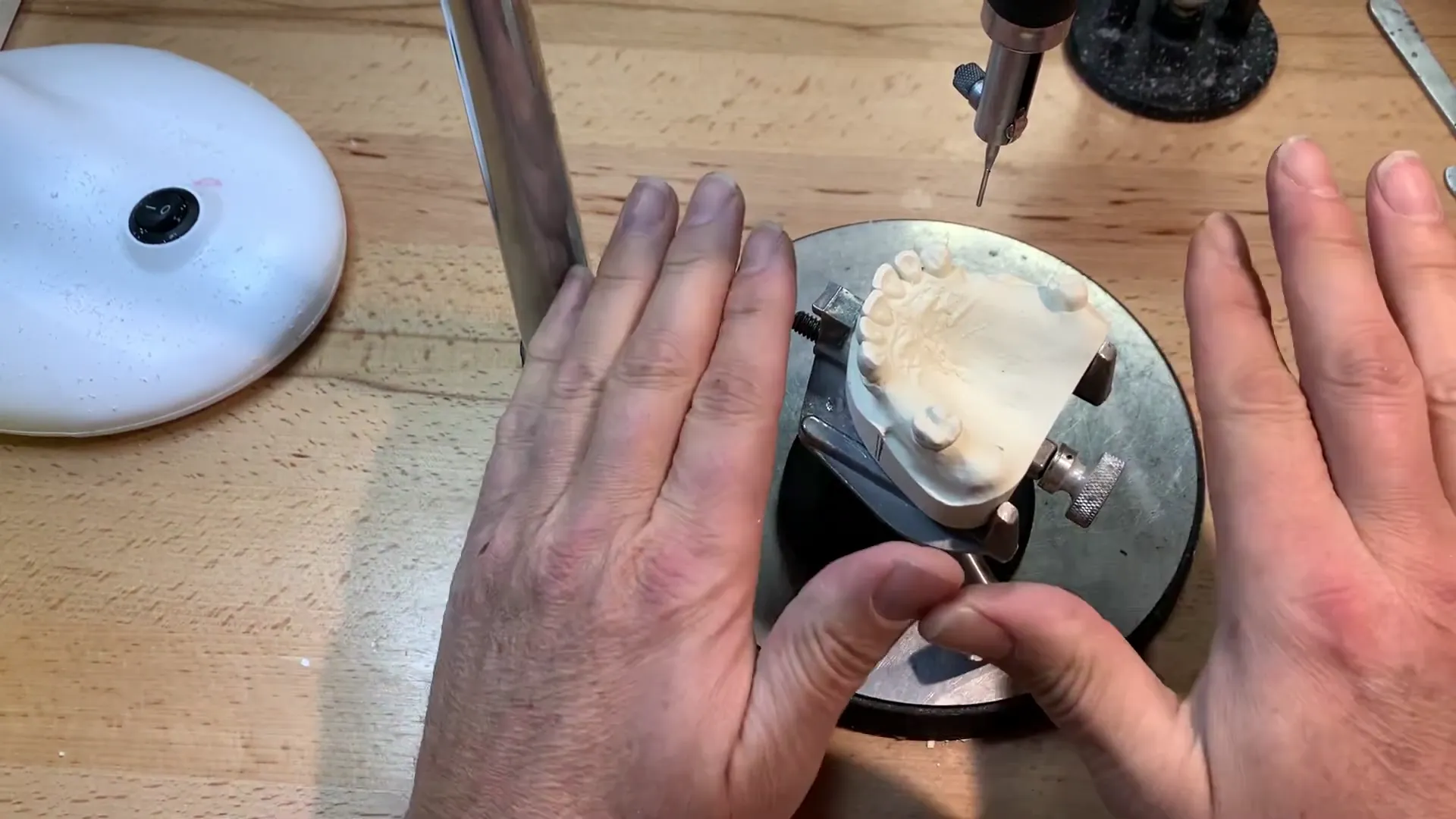
To ensure the model can be re-seated on the surveyor at the correct angle, use one of two methods:
- X-Axis Method: Mark the x-axis on the sides and back of the model base
 .
2. Three-Point Method: Mark three widely spaced “bullseye” circles
.
2. Three-Point Method: Mark three widely spaced “bullseye” circles
 (approx. 3mm diameter) on the tissue surface of the model.
Blockout and Ledging
- Proximal Surfaces: Apply wax below the height of contour on all four abutment teeth
. Use the analyzing rod to parallel these surfaces to the path of insertion.
- Gingival Margins: Lightly block out the free gingival margins to prevent metal impingement.
- Ledging: Create a sharp ledge in the wax at the survey line for the Akers clasps on the molars. This acts as a guide for the wax pattern. Do not ledge the guide planes or the anterior wrought wire areas.
- Horizontal Shoe Extensions: Incorporate 0.6mm wax extensions distal to the canines and mesial to the molars. This provides a clean internal finishing line
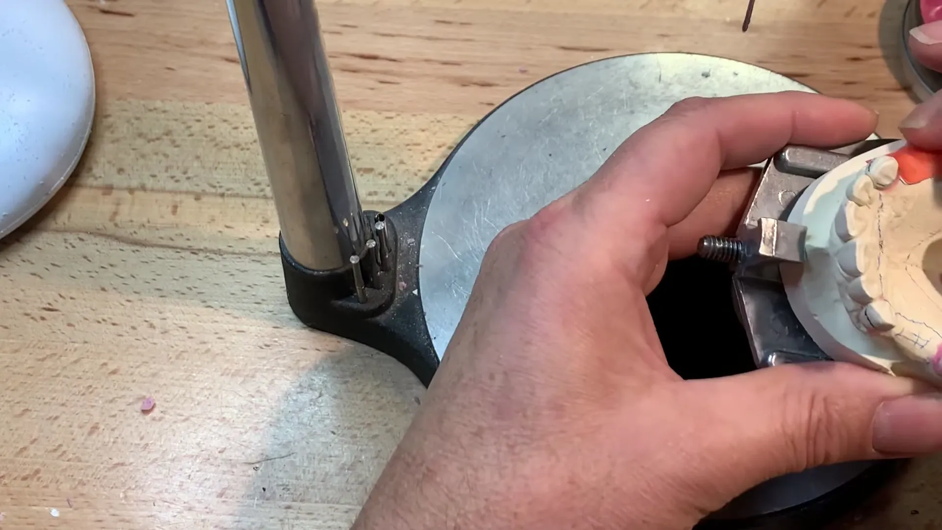 for the acrylic-to-metal junction.
Finalization for Duplication
- Bead Line: Score a faint bead line at the anterior and posterior borders of the major connector (avoiding the median suture and incisive papilla).
- Prescription Check: Ensure the physical model design matches the written prescription and evaluation guide.
- Duplication: Once blocked out and scored, the model is ready for duplication in silicone to create the refractory model.