Intraoral Radiographic Anatomy1
Dr Dayea Oh OMF Radiologist
BW, PA & Occlusograph Anatomy2
- Dental structures
- Osseous structures
- Canals and foramina
- Artefacts
References and Recommended Textbooks3
-
Essentials of dental radiography and radiology 5th edition by Whaites, Eric; Drage, Nicholas. Churchill Livingstone 2013
-
Pocket atlas of dental radiology by Pasler, Friedrich A; Visser, Heiko. Flexibook, 2007
-
Oral radiology: principles and interpretation 7th edition by White, Stuart C; Pharoah, M. J. Permalink 2014
- 8th edition available now
Dental Structures and Restorations
Anatomy of the Teeth4
Teeth
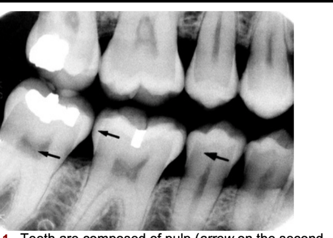
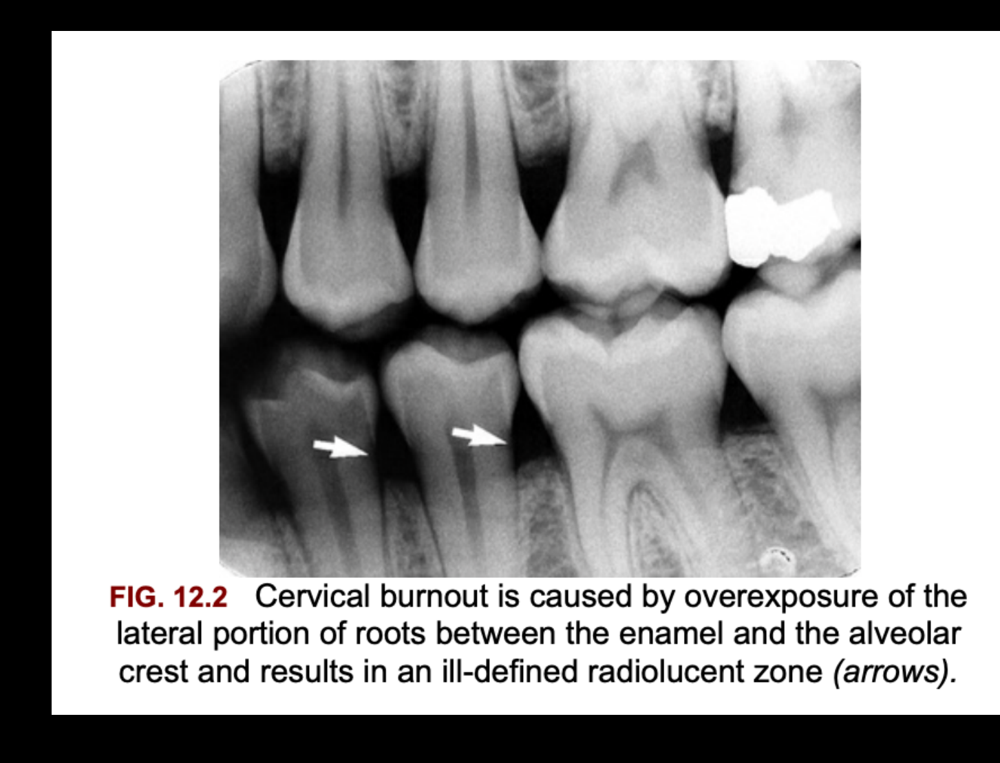
Cervical Burnout5
FIG. 12.2 Cervical burnout is caused by overexposure of the lateral portion of roots between the enamel and the alveolar crest and results in an ill-defined radiolucent zone (arrows).
Root Canal and Apical Structures
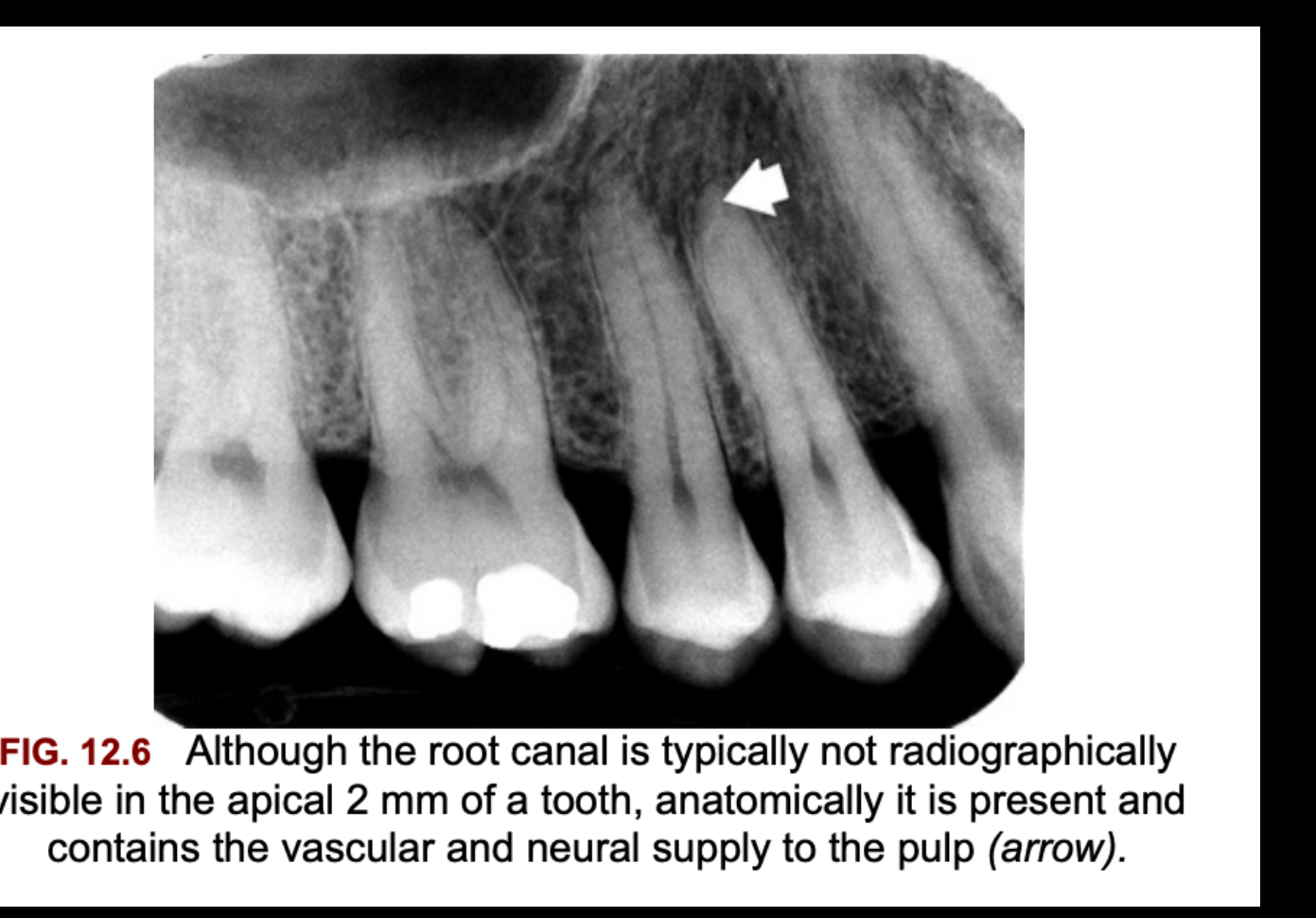
Root Canal – Apical third6
FIG. 12.6 Although the root canal is typically not radiographically visible in the apical 2 mm of a tooth, anatomically it is present and contains the vascular and neural supply to the pulp (arrow).
Developing Roots and Mixed Dentition
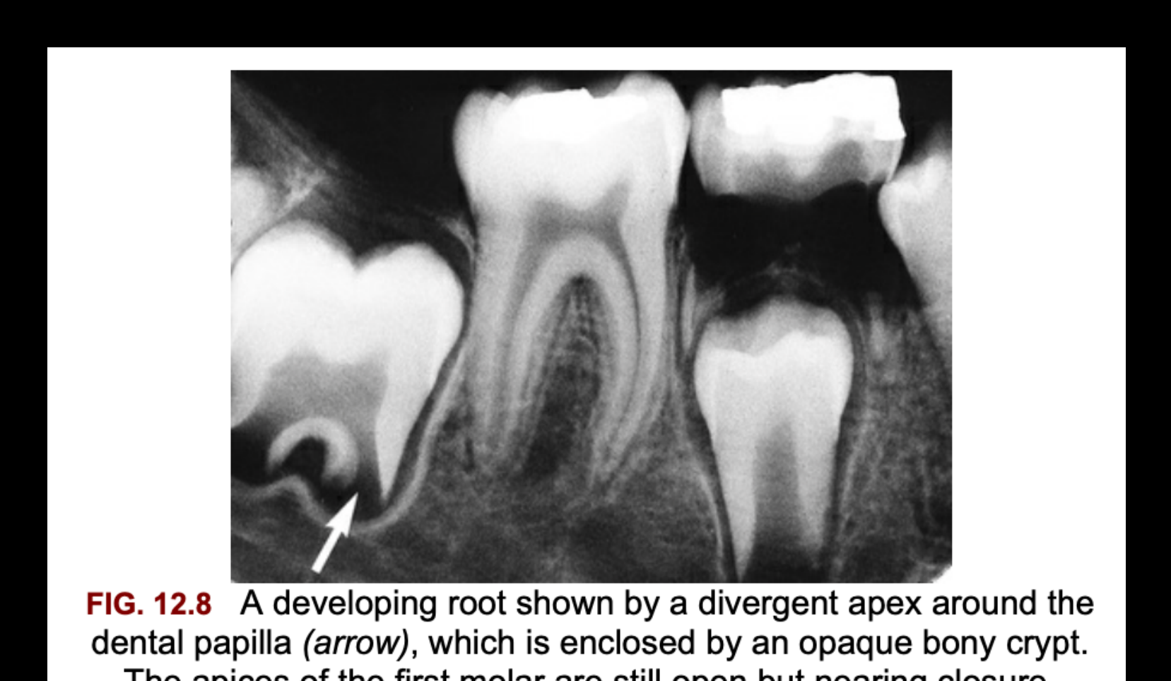
Mixed Dentition – Developing Roots7
FIG. 12.8 A developing root shown by a divergent apex around the dental papilla (arrow), which is enclosed by an opaque bony crypt. The apices of the first molar are still open but nearing closure.
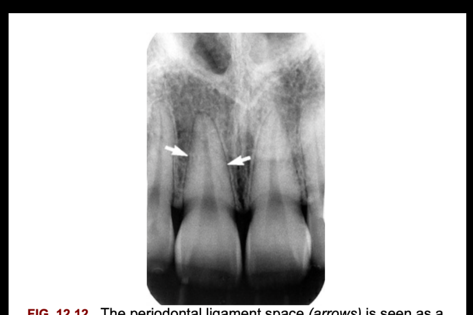
Periodontal Ligament Space and Lamina Dura8
Periodontal Ligament Space9
FIG. 12.12 The periodontal ligament space (arrows) is seen as a narrow radiolucency between the tooth root and the lamina dura.
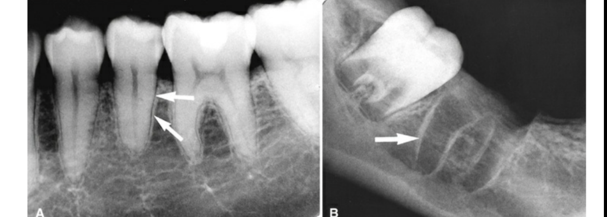
Lamina Dura
A B
Restorative and Orthodontic Therapy
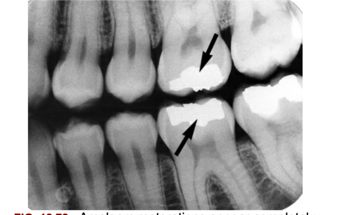
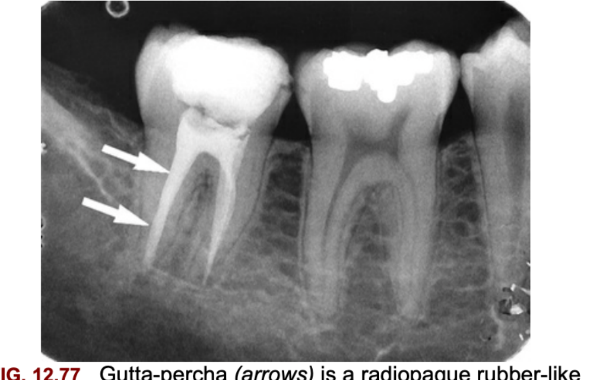
Restorative Therapy10
- FIG. 12.72 Amalgam restorations appear completely radiopaque (arrows).
- FIG. 12.77 Gutta-percha (arrows) is a radiopaque rubber-like material used in endodontic therapy.
 |  |
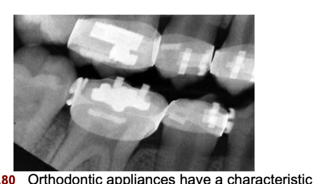
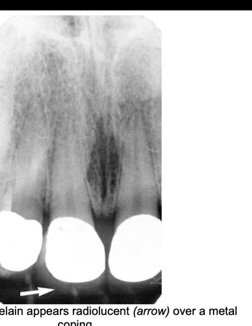
Orthodontic therapy & Crowns11
- FIG. 12.80 Orthodontic appliances have a characteristic radiopaque appearance.
- FIG. 12.79 Porcelain appears radiolucent (arrow) over a metal coping.
 |  |
Osseous Structures of the Maxilla
Alveolar Bone and Trabecular Pattern
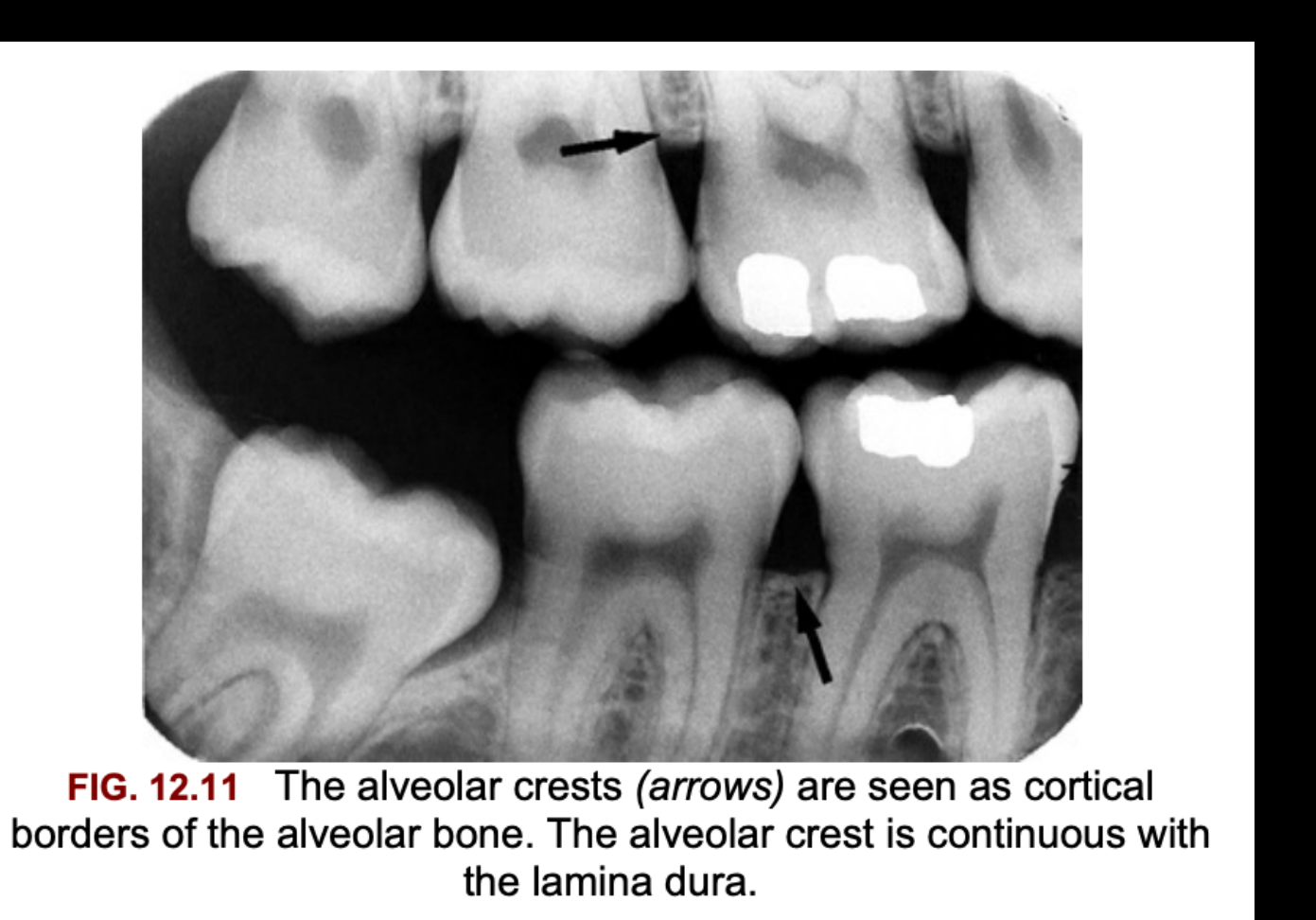
Alveolar Crest12
FIG. 12.11 The alveolar crests (arrows) are seen as cortical borders of the alveolar bone. The alveolar crest is continuous with the lamina dura.
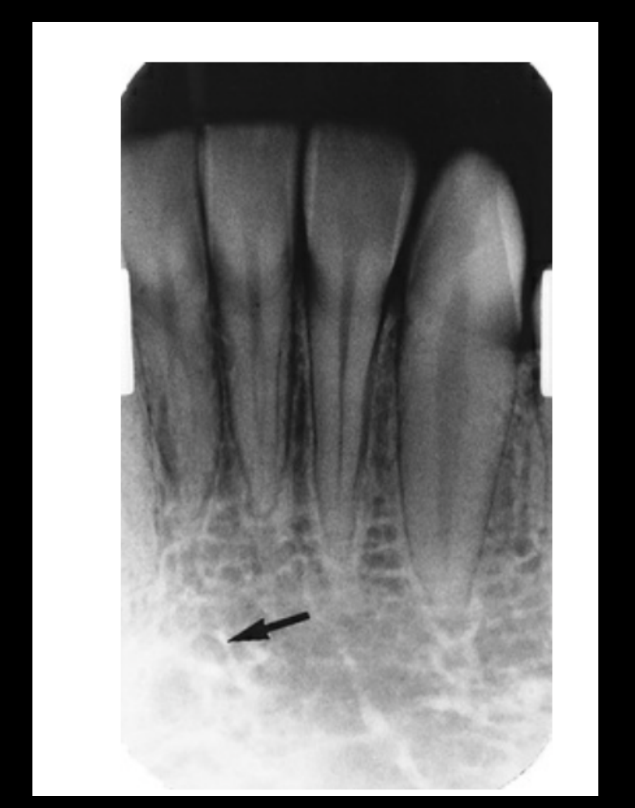
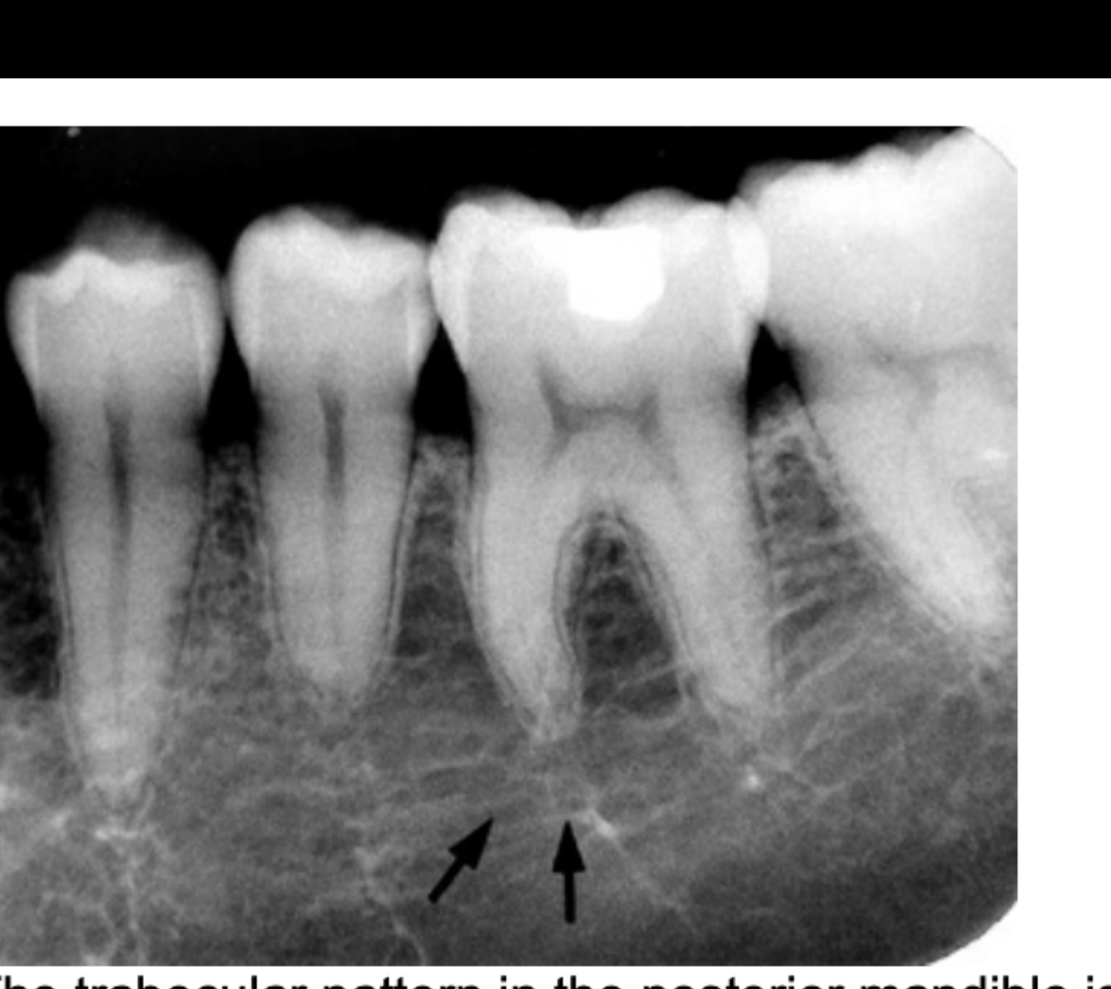
Trabecular Pattern13
FIG. 12.17 The trabecular pattern in the posterior mandible is quite variable, generally showing large marrow spaces and sparse trabeculation, especially inferiorly (arrows).
 |  |
Midline Maxillary Landmarks
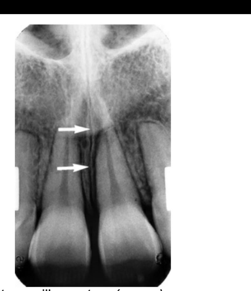
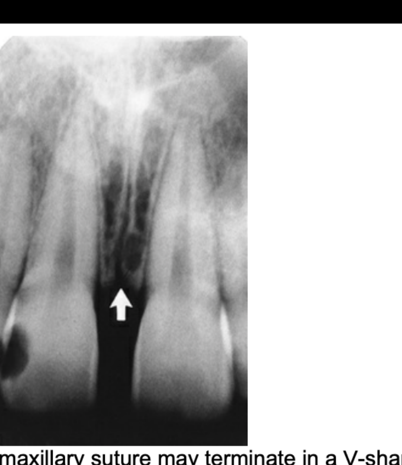
Intermaxillary Suture14
FIG. 12.19 The intermaxillary suture (arrows) appears as a curved radiolucency in the midline of the maxilla.
FIG. 12.20 The intermaxillary suture may terminate in a V-shaped widening (arrow) at the alveolar crest. This is a normal variation and should not be confused with alveolar bone loss associated with periodontal disease.
 |  |
Anterior Nasal Spine and Septum15
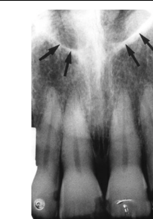 |  |
Anterior Nasal Spine16
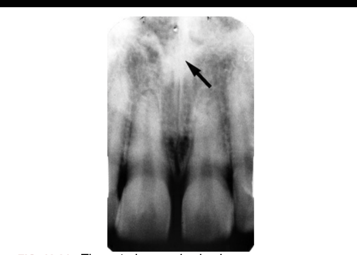
FIG. 12.21 The anterior nasal spine is seen as an opaque, irregular, or V-shaped projection from the floor of the nasal aperture in the midline (arrow).
- FIG. 12.22 The anterior floor of the nasal aperture (arrows) appears as opaque lines extending laterally from the anterior nasal spine.
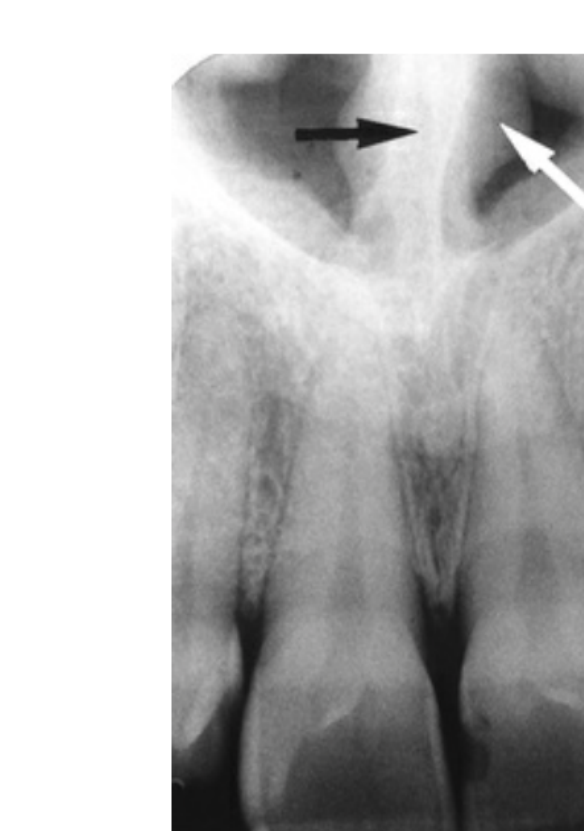
- FIG. 12.23 The nasal septum (black arrow) arises directly above the anterior nasal spine and is covered on each side by mucosa (white arrow).
Nasal Cavity and Associated Canals
Nasal Floor17
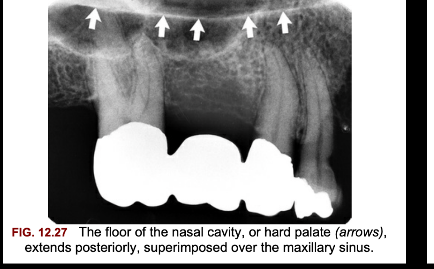
- FIG. 12.27 The floor of the nasal cavity, or hard palate (arrows), extends posteriorly, superimposed over the maxillary sinus.
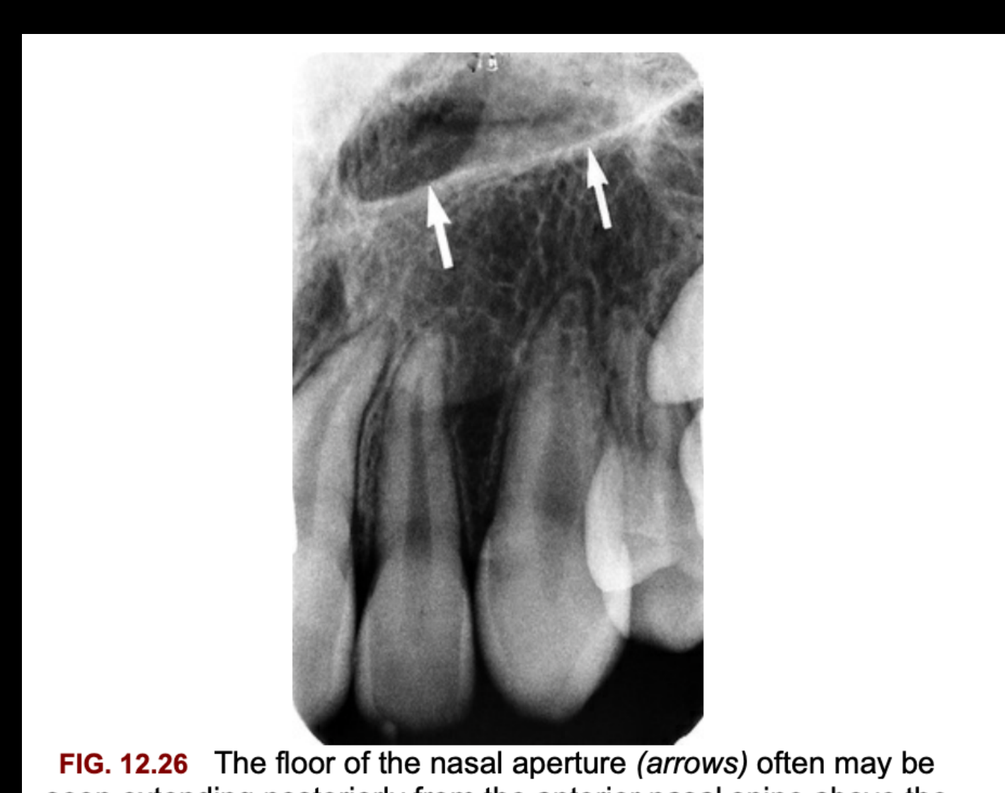
- FIG. 12.26 The floor of the nasal aperture (arrows) often may be seen extending posteriorly from the anterior nasal spine above the maxillary lateral incisor and canine.
 |  |
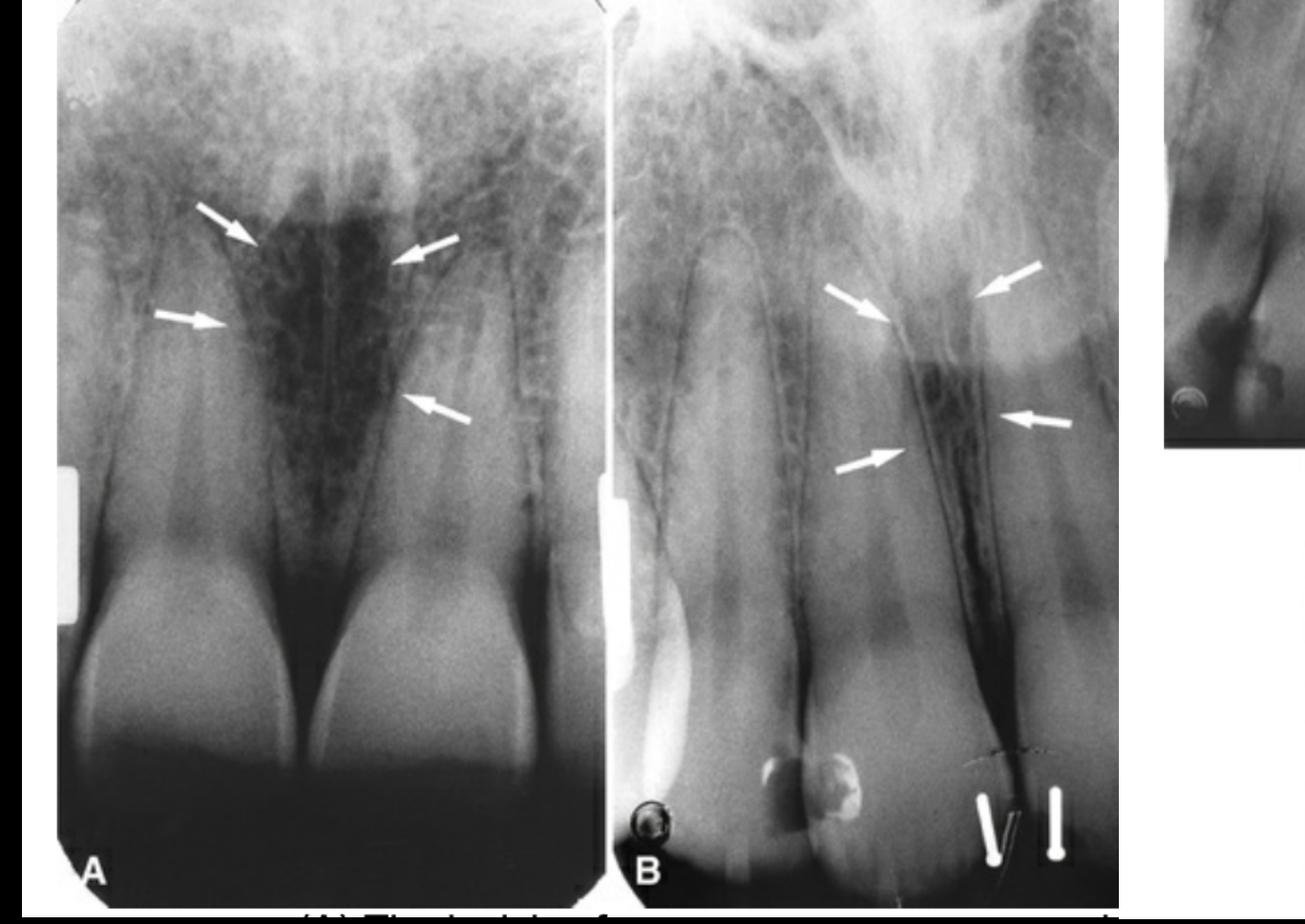
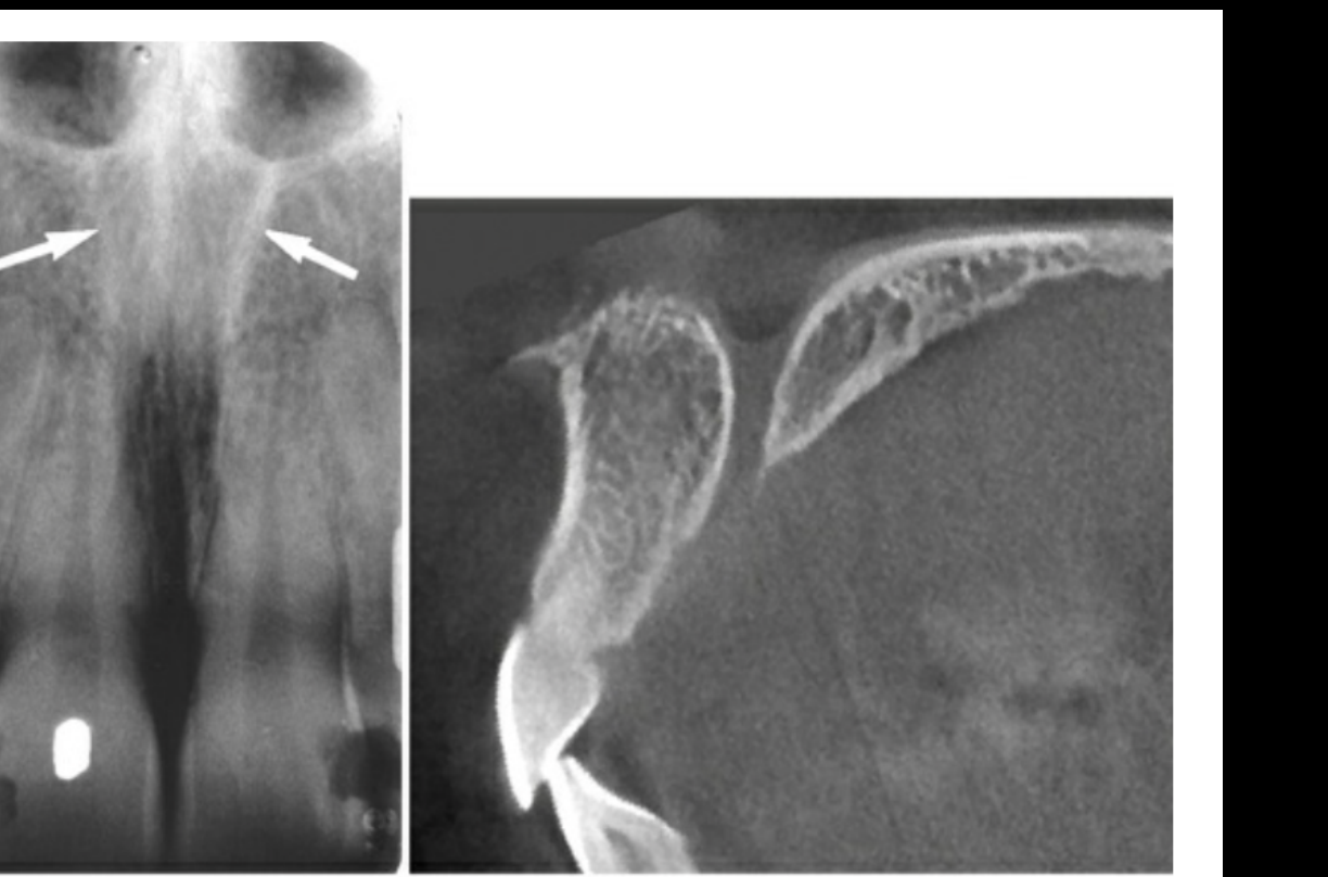
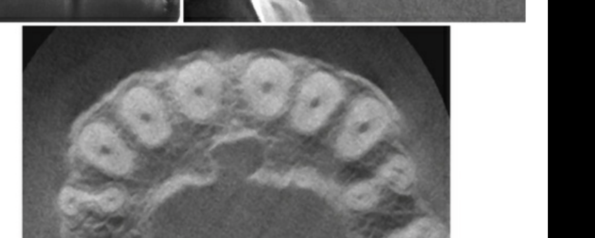
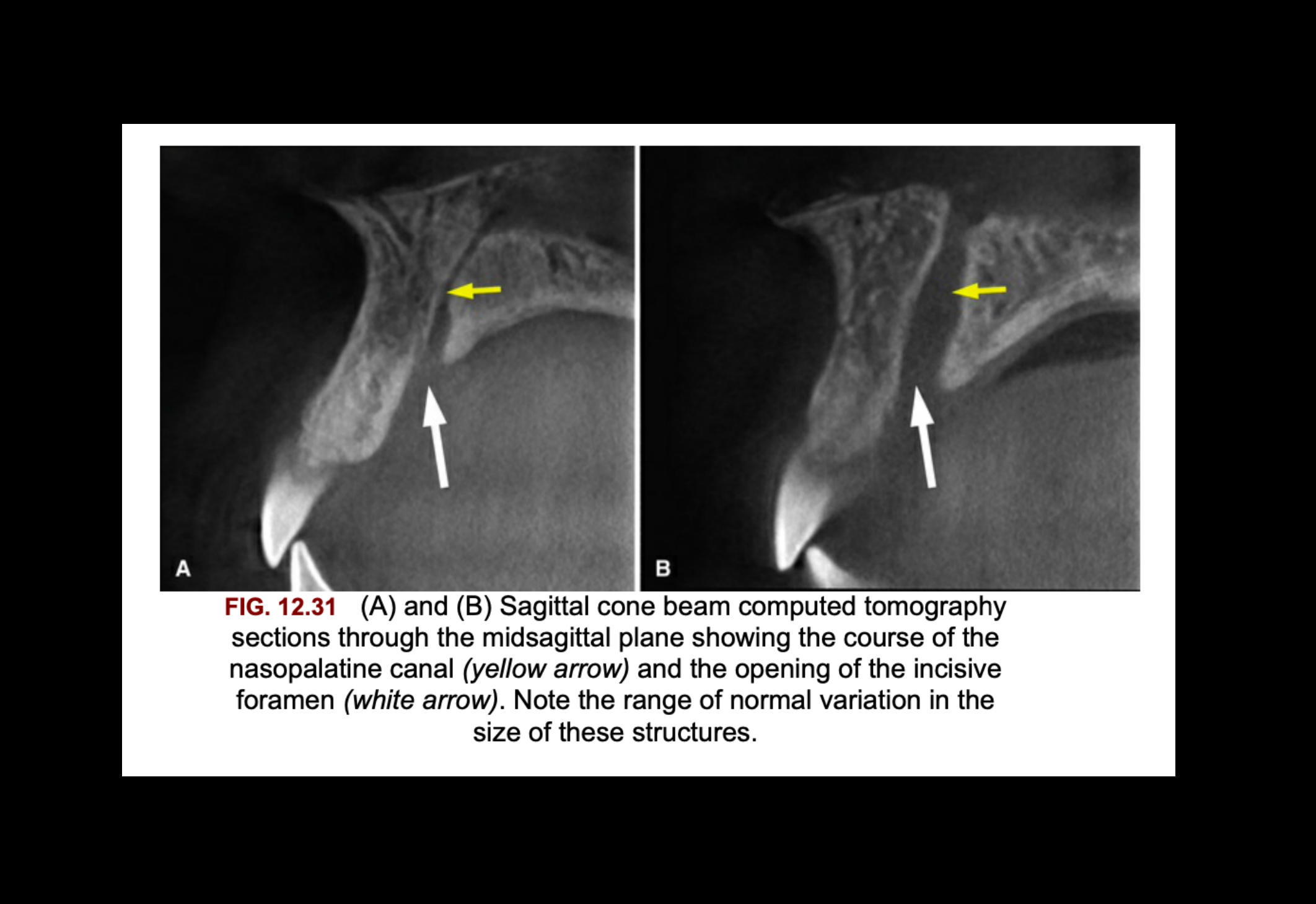
Incisive Canal and Nasopalatine Foramina181920
Incisive Canal
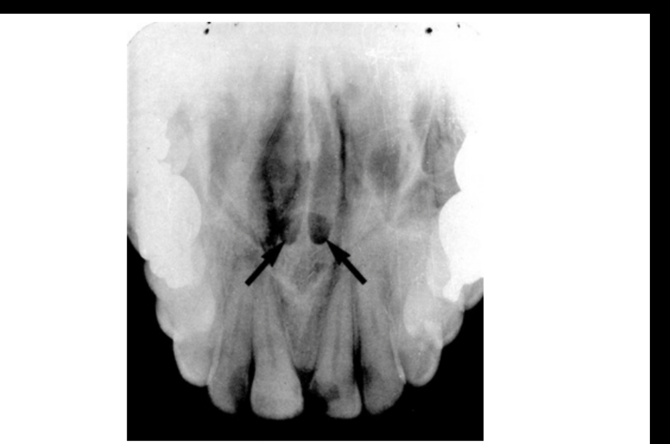
FIG. 12.30 The superior foramina of the nasopalatine canal (arrows) appear just lateral to the nasal septum and posterior to the anterior nasal spine.
 |  |  |
 |  |
Lateral Fossa21
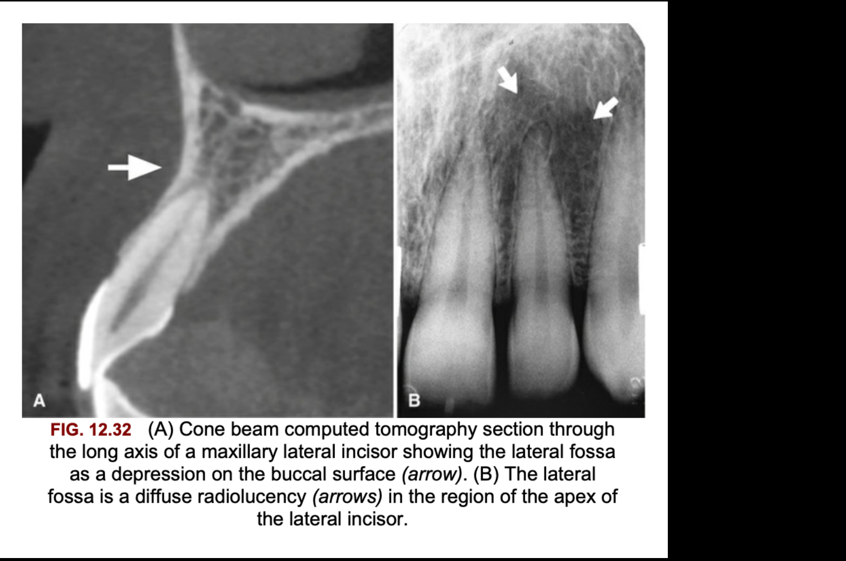
FIG. 12.32 (A) Cone beam computed tomography section through the long axis of a maxillary lateral incisor showing the lateral fossa as a depression on the buccal surface (arrow). (B) The lateral fossa is a diffuse radiolucency (arrows) in the region of the apex of the lateral incisor.
Maxillary Sinus and Soft Tissue22
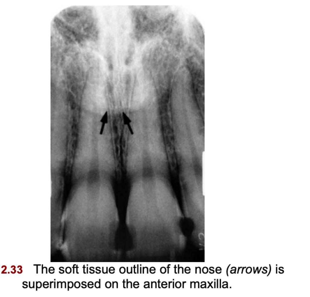
Soft Tissue of the Nose
Nasolacrimal Canals23
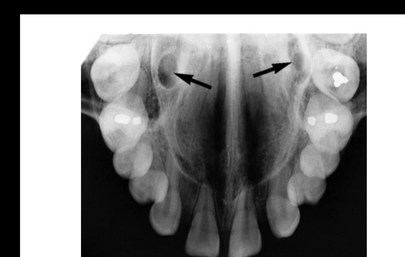
FIG. 12.35 The nasolacrimal canals are commonly seen as ovoid radiolucencies (arrows) on maxillary occlusal projections. They should not be confused with the greater palatine foramina, which are not apparent on maxillary occlusal projections.
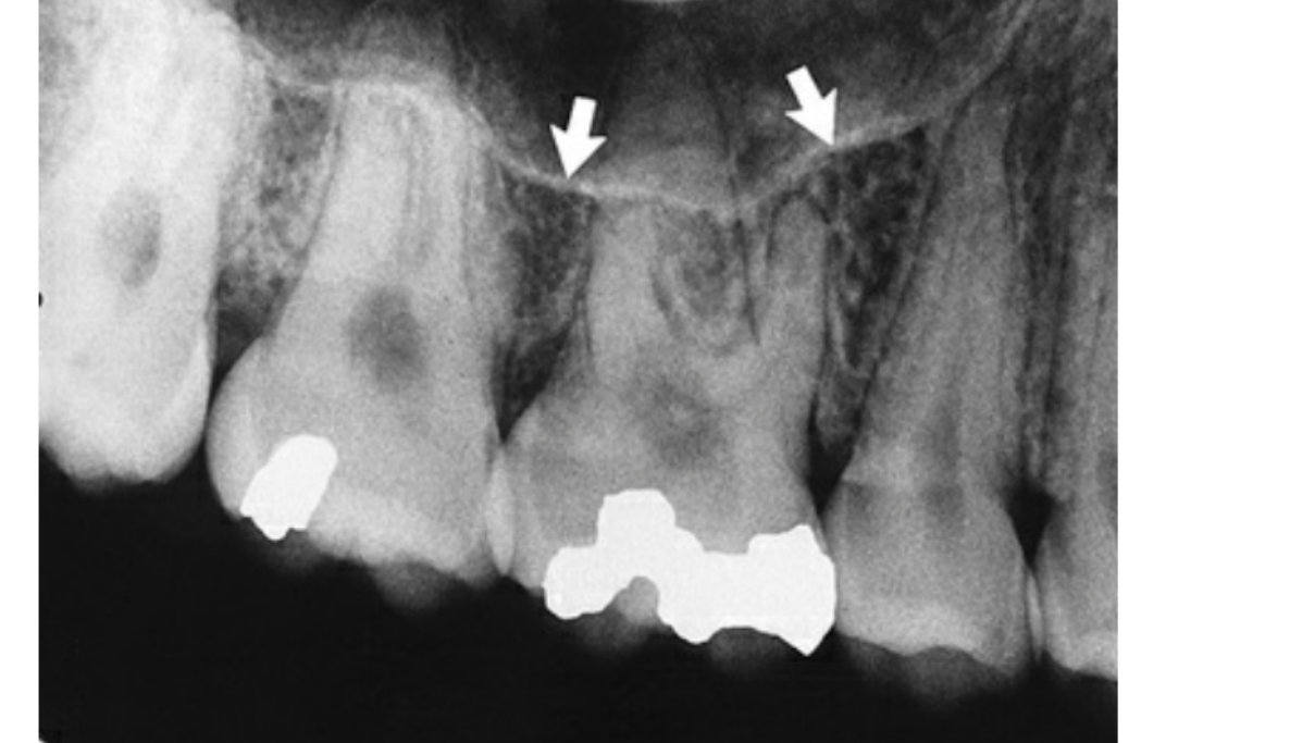
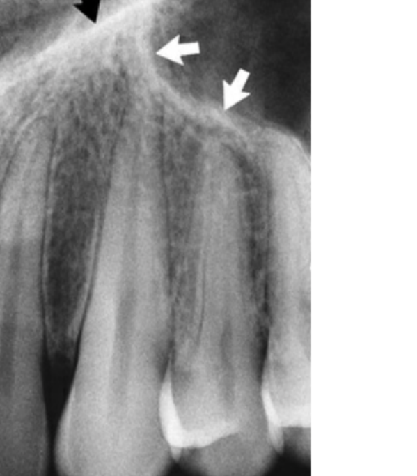
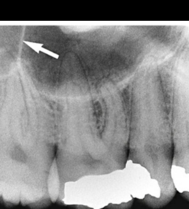
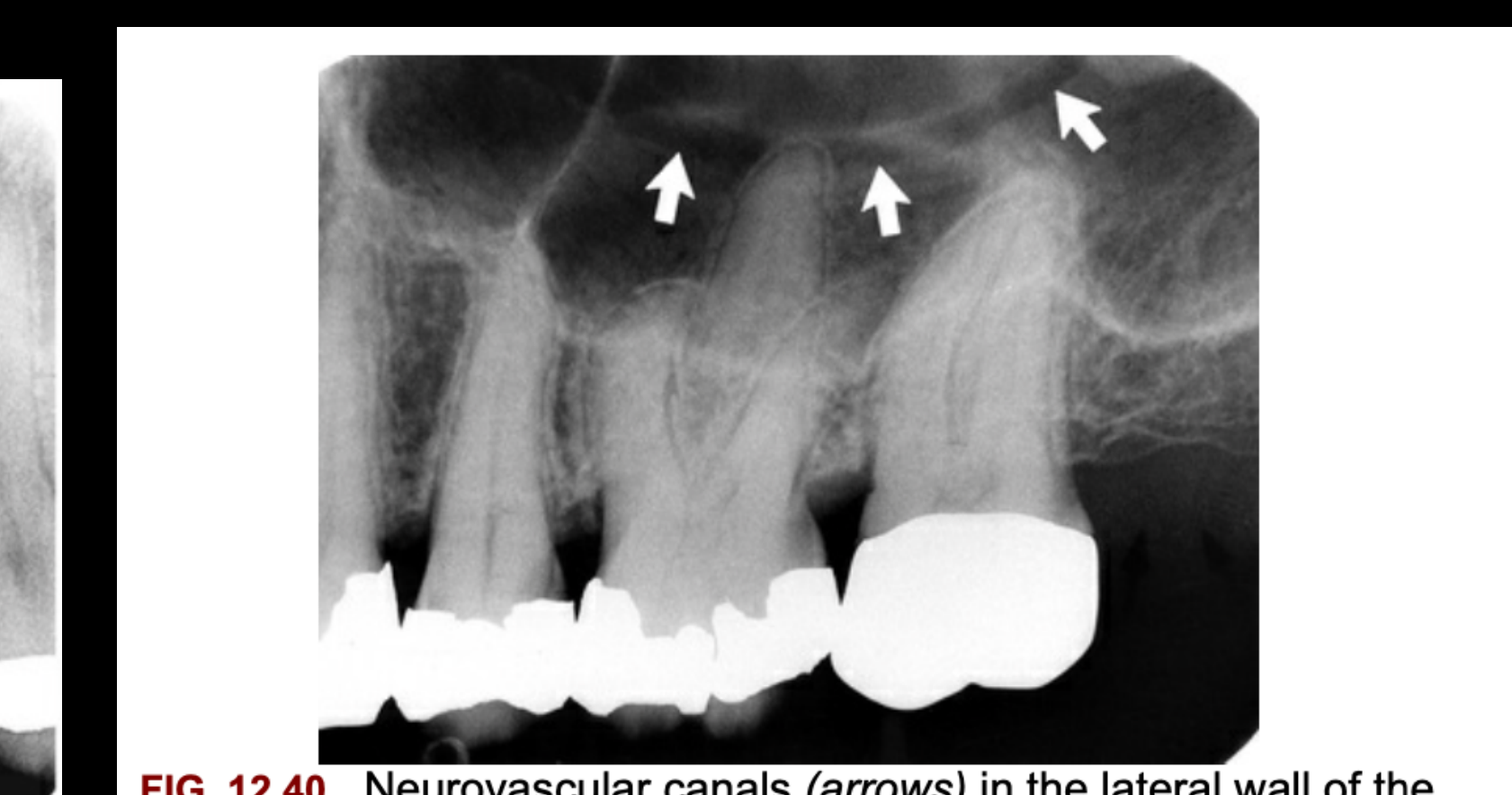
Maxillary Sinus Anatomy242526
- FIG. 12.36 The inferior border of the maxillary sinus (arrows) appears as a thin radiopaque line near the apices of the maxillary premolars and molars.
- FIG. 12.37 The anterior border of the maxillary sinus (white arrows) crosses the floor of the nasal fossa (black arrow).
Dental X-ray showing neurovascular canals in the maxillary sinus
 |  |  |
 | 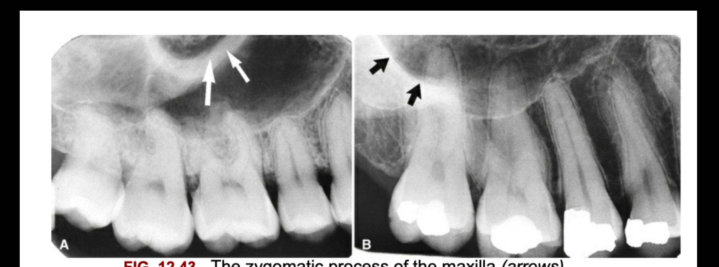 |
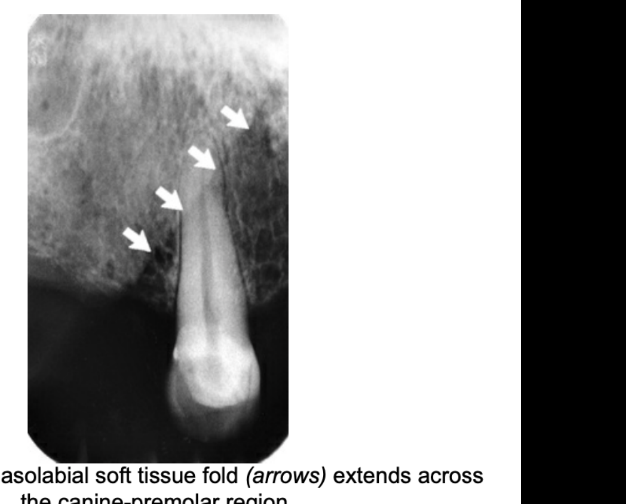
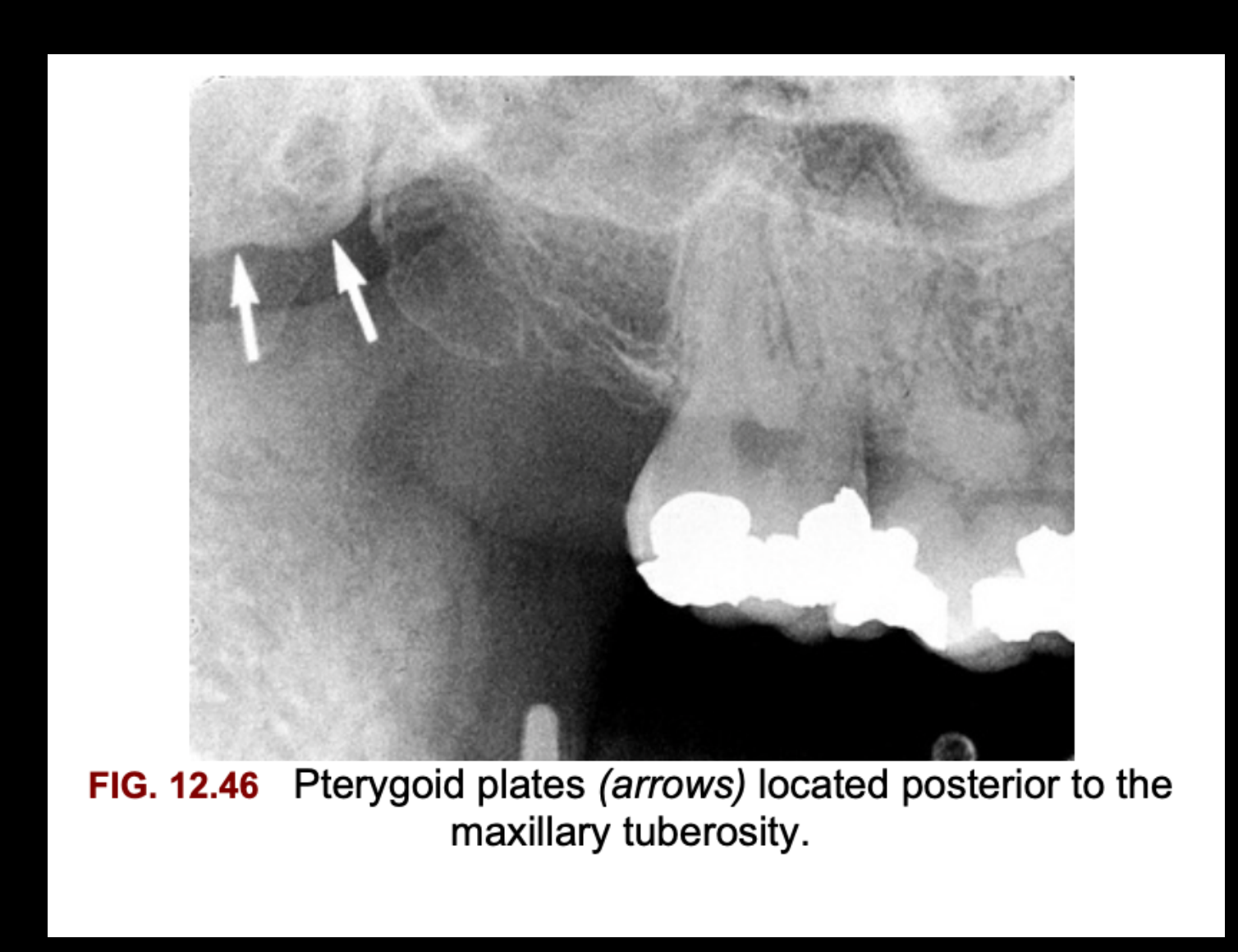
Nasolabial Fold and Soft Tissue2728
Soft tissue shadow line across palate
 |  |
Osseous Structures of the Mandible
Midline Mandibular Landmarks
Genial Tubercles and Lingual Foramen2930
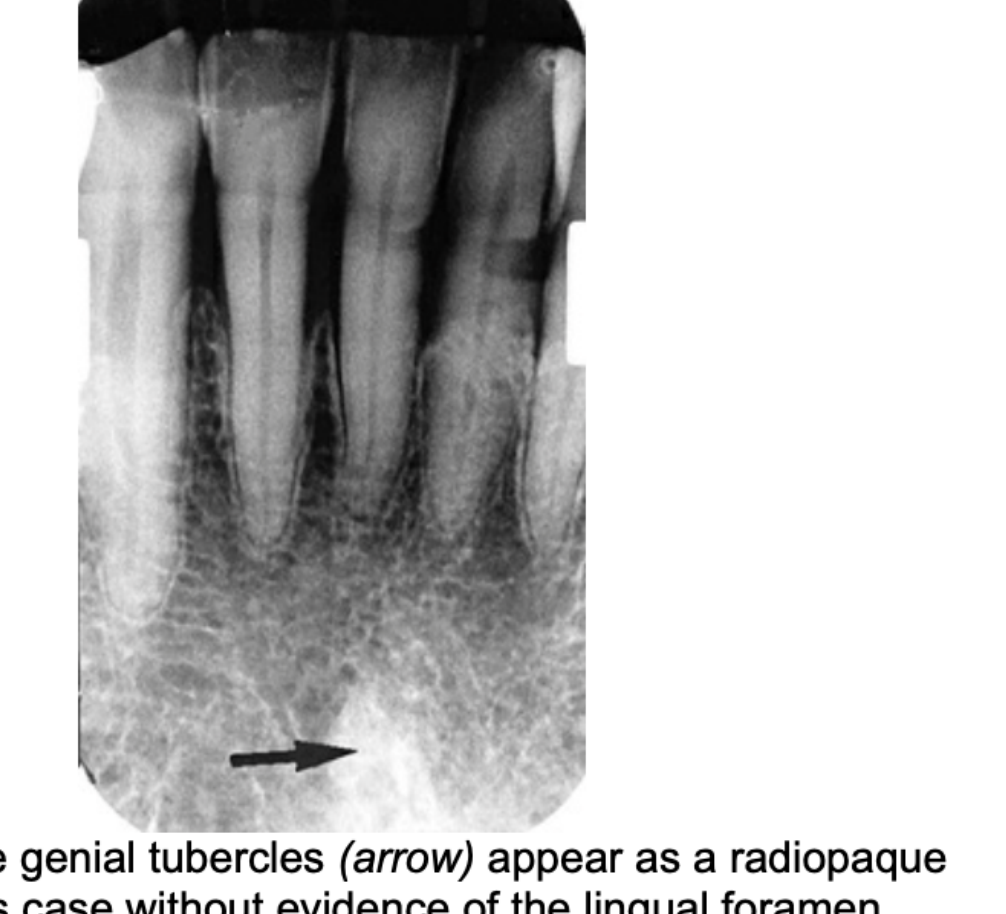
FIG. 12.50 The genial tubercles (arrow) appear as a radiopaque mass, in this case without evidence of the lingual foramen.
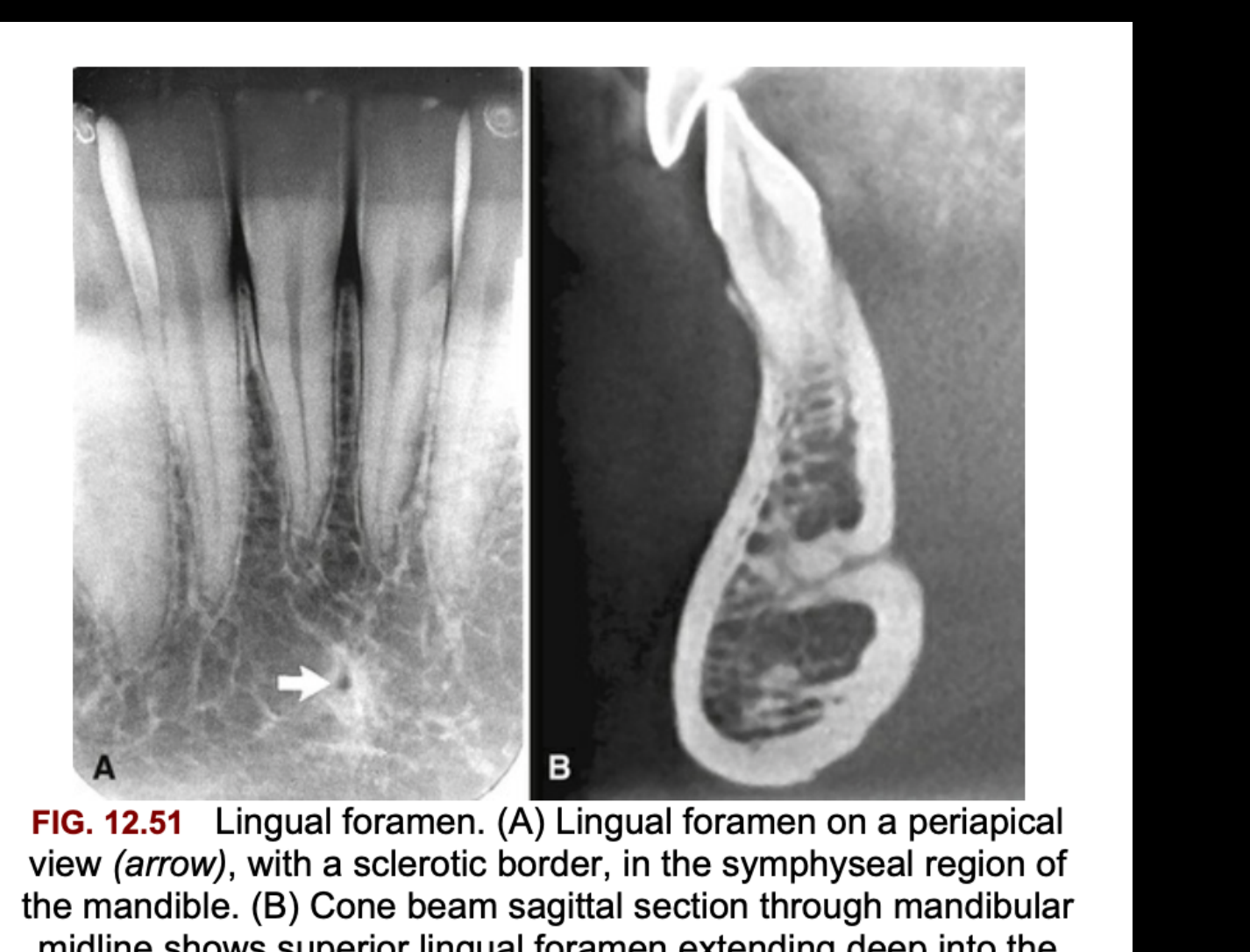
Lingual foramen. (A) Lingual foramen on a periapical view (arrow), with a sclerotic border, in the symphyseal region of the mandible. (B) Cone beam sagittal section through mandibular midline shows superior lingual foramen extending deep into the mandible from the lingual surface.
 |  |
Mental Fossa31
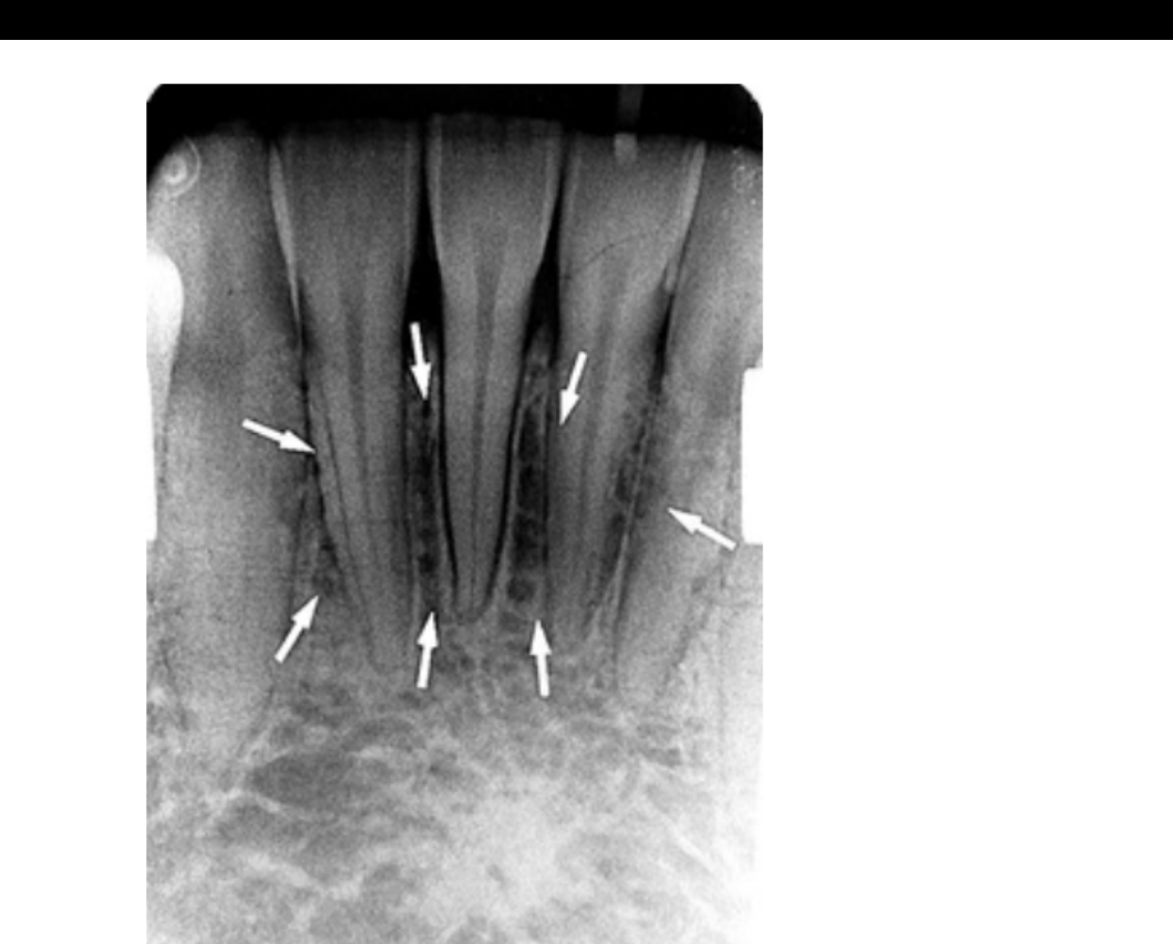
FIG. 12.53 The mental fossa is a depression on the anterior surface of the mandible and is seen as a radiolucent area with ill-defined borders (arrows) in the region of the incisor roots.
Mandibular Canals and Foramina
Mental Foramen32
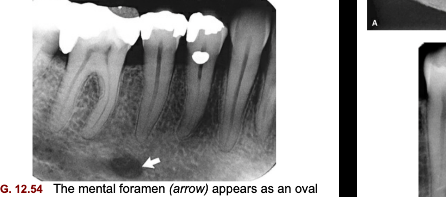
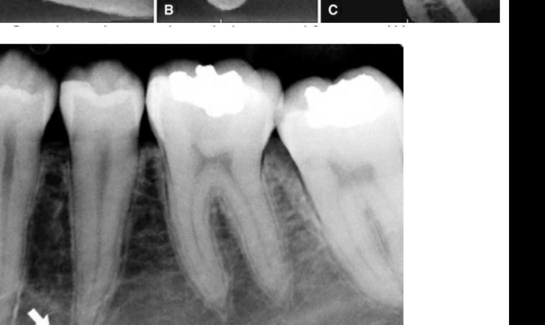
- FIG. 12.54 The mental foramen (arrow) appears as an oval radiolucency typically near the apex of the second premolar.
- FIG. 12.56 The mental foramen (arrow) (over the apex of the second premolar) may simulate periapical disease. However, continuity of the lamina dura around the apex indicates the absence of periapical abnormality.
 |  |
 |
Mandibular Canal and Nutrient Canals333435
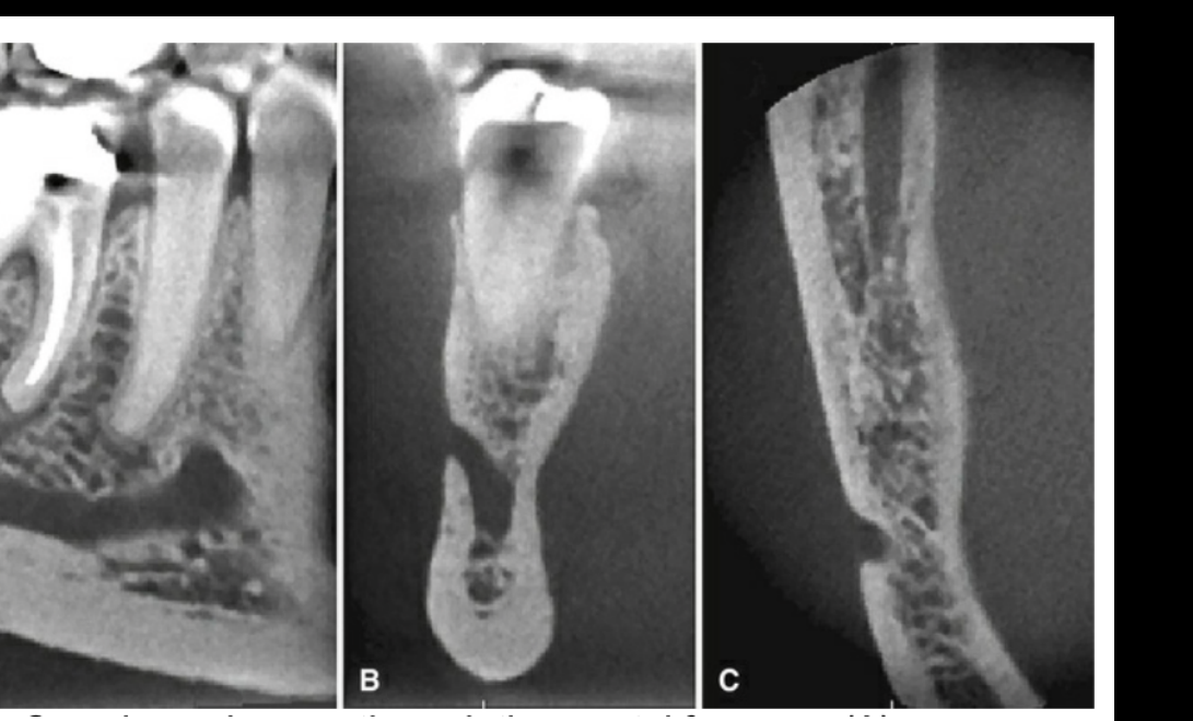
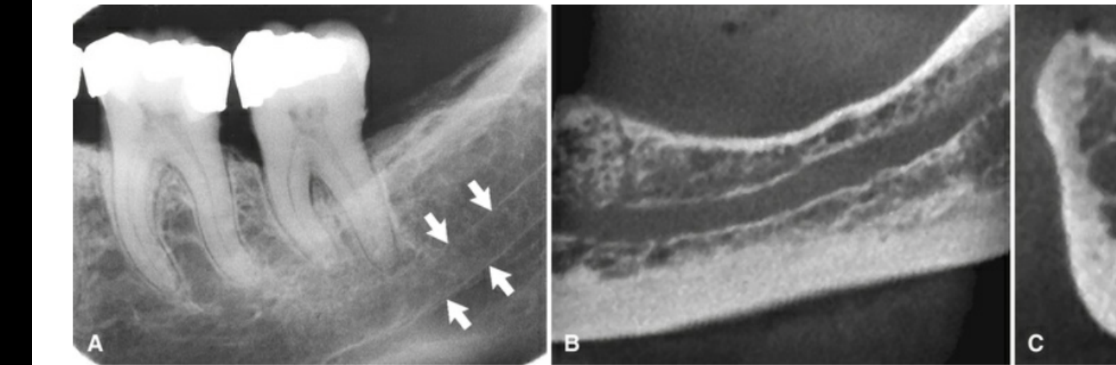
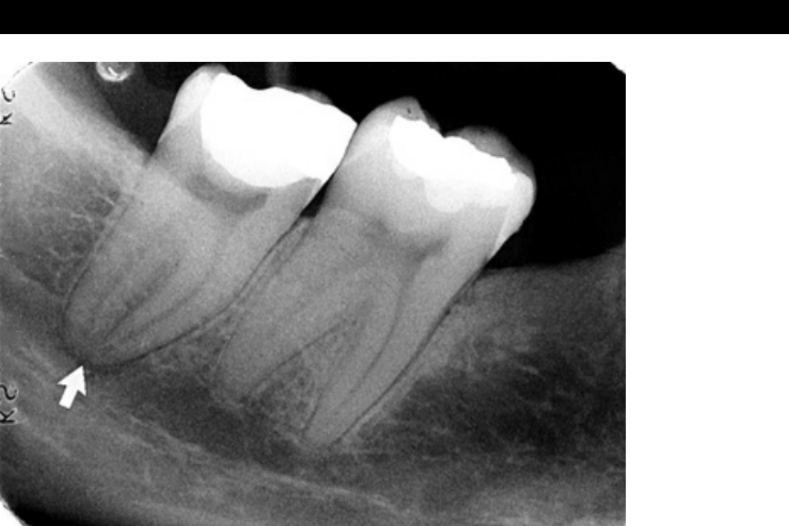
FIG. 12.57 Inferior alveolar canal. (A) On periapical view, arrows denote radiopaque superior and inferior cortical borders. (B) Cone beam section through the body of the mandible (different patient) shows corticated borders of the inferior alveolar canal. (C) Cone beam cross-sectional view shows the circular inferior alveolar canal with corticated borders lying adjacent to the lingual plate.
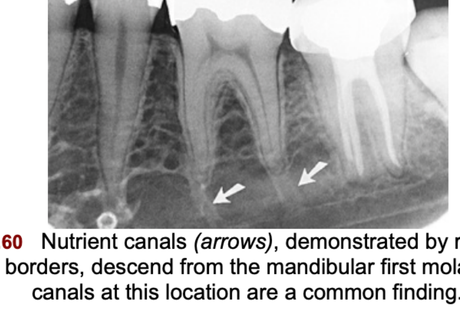
- FIG. 12.60 Nutrient canals (arrows), demonstrated by radiopaque cortical borders, descend from the mandibular first molar. Nutrient canals at this location are a common finding.
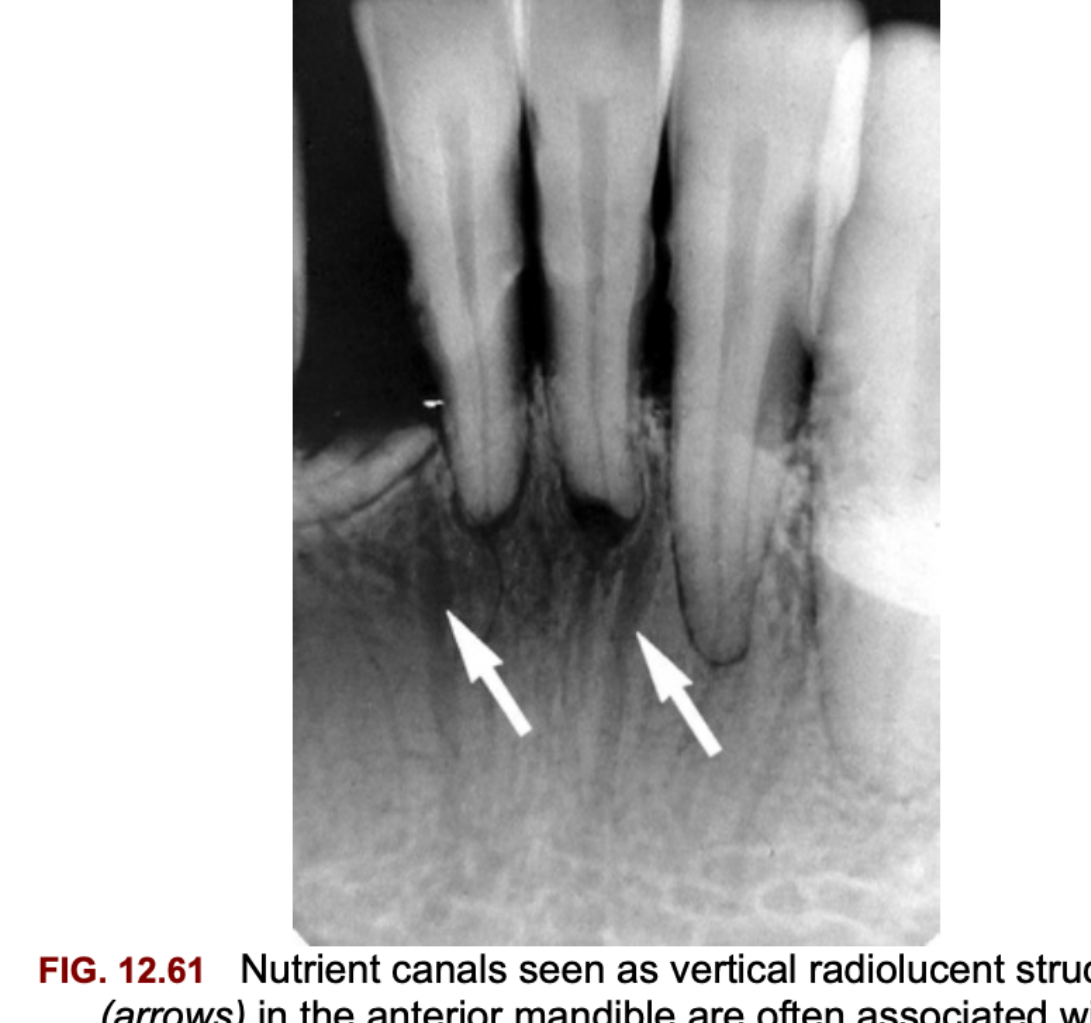
- FIG. 12.61 Nutrient canals seen as vertical radiolucent structures (arrows) in the anterior mandible are often associated with periodontal disease as in this patient.
 |  |
 |  |
Mandibular Ridges and Fossae
Mylohyoid Ridge36
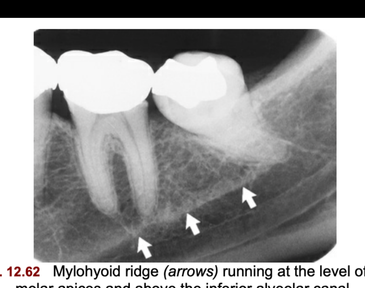
FIG. 12.62 Mylohyoid ridge (arrows) running at the level of the molar apices and above the inferior alveolar canal.
Submandibular Fossa37
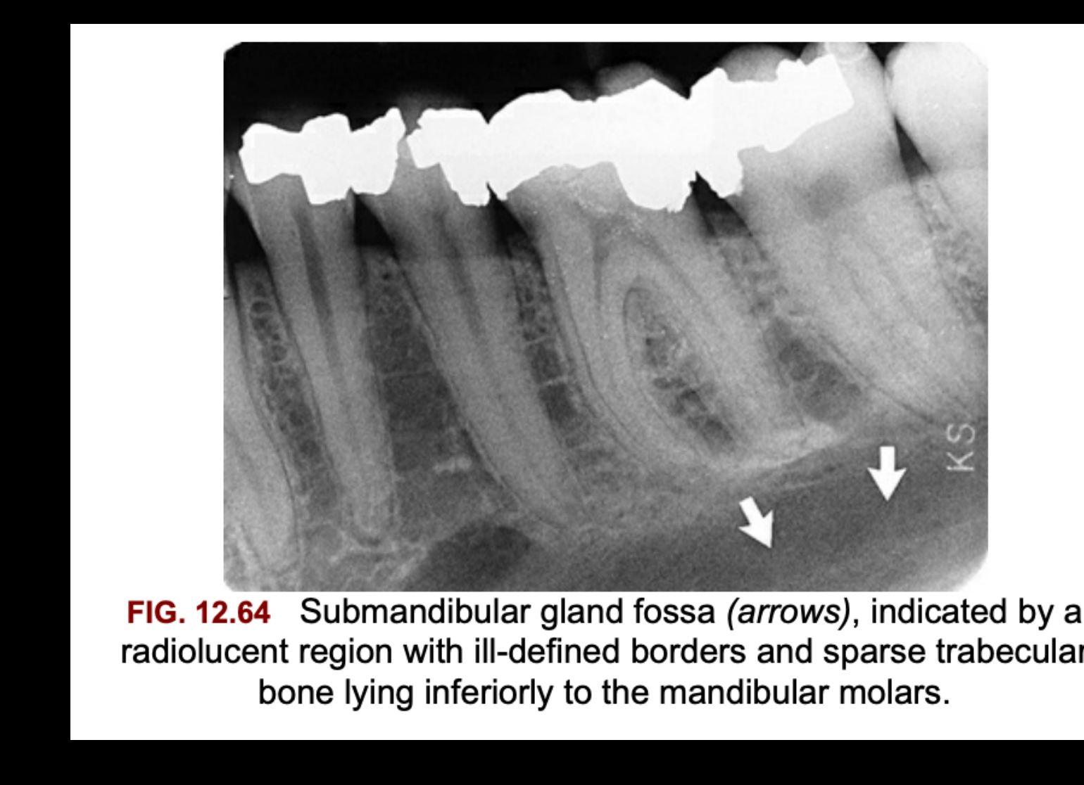
FIG. 12.64 Submandibular gland fossa (arrows), indicated by a radiolucent region with ill-defined borders and sparse trabecular bone lying inferiorly to the mandibular molars.
External Oblique Ridge38
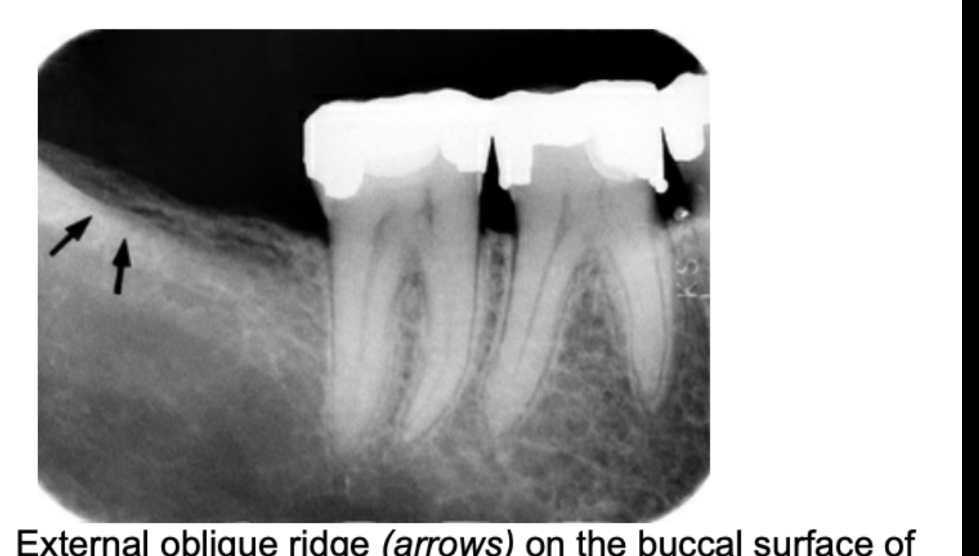
FIG. 12.65 External oblique ridge (arrows) on the buccal surface of the mandible, seen as a radiopaque line near the alveolar crest in the mandibular third molar region.
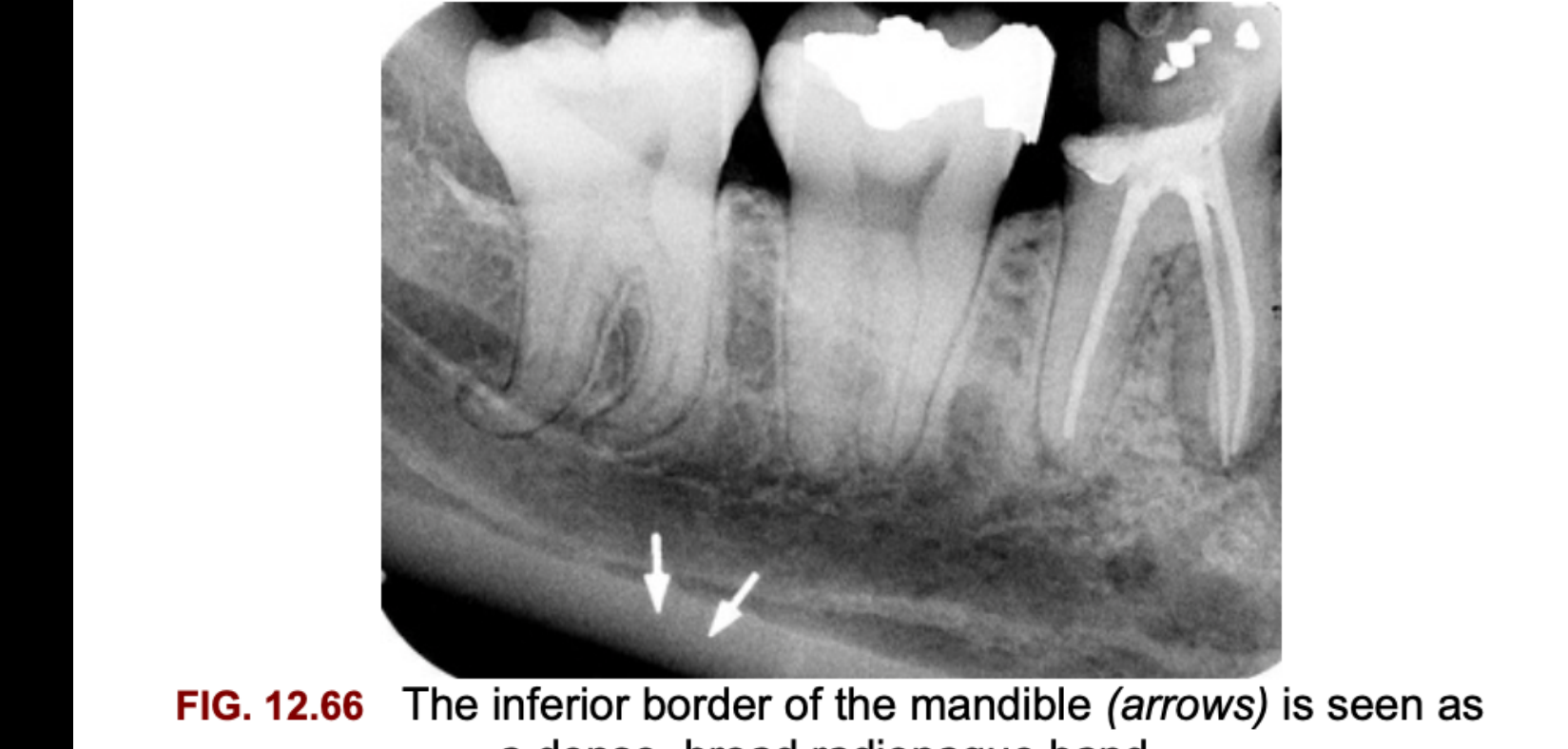
Inferior Cortical Border of the Mandible3940
FIG. 12.66 The inferior border of the mandible (arrows) is seen as a dense, broad radiopaque band.
End.
Footnotes
-
Original PDF page 1: L5 Intraoral Radiographic Anatomy, p.1 ↩
-
Original PDF page 2: L5 Intraoral Radiographic Anatomy, p.2 ↩
-
Original PDF page 3: L5 Intraoral Radiographic Anatomy, p.3 ↩
-
Original PDF page 4: L5 Intraoral Radiographic Anatomy, p.4 ↩
-
Original PDF page 5: L5 Intraoral Radiographic Anatomy, p.5 ↩
-
Original PDF page 6: L5 Intraoral Radiographic Anatomy, p.6 ↩
-
Original PDF page 7: L5 Intraoral Radiographic Anatomy, p.7 ↩
-
Original PDF page 9: L5 Intraoral Radiographic Anatomy, p.9 ↩
-
Original PDF page 8: L5 Intraoral Radiographic Anatomy, p.8 ↩
-
Original PDF page 10: L5 Intraoral Radiographic Anatomy, p.10 ↩
-
Original PDF page 11: L5 Intraoral Radiographic Anatomy, p.11 ↩
-
Original PDF page 12: L5 Intraoral Radiographic Anatomy, p.12 ↩
-
Original PDF page 13: L5 Intraoral Radiographic Anatomy, p.13 ↩
-
Original PDF page 14: L5 Intraoral Radiographic Anatomy, p.14 ↩
-
Original PDF page 16: L5 Intraoral Radiographic Anatomy, p.16 ↩
-
Original PDF page 15: L5 Intraoral Radiographic Anatomy, p.15 ↩
-
Original PDF page 17: L5 Intraoral Radiographic Anatomy, p.17 ↩
-
Original PDF page 18: L5 Intraoral Radiographic Anatomy, p.18 ↩
-
Original PDF page 19: L5 Intraoral Radiographic Anatomy, p.19 ↩
-
Original PDF page 20: L5 Intraoral Radiographic Anatomy, p.20 ↩
-
Original PDF page 21: L5 Intraoral Radiographic Anatomy, p.21 ↩
-
Original PDF page 22: L5 Intraoral Radiographic Anatomy, p.22 ↩
-
Original PDF page 23: L5 Intraoral Radiographic Anatomy, p.23 ↩
-
Original PDF page 24: L5 Intraoral Radiographic Anatomy, p.24 ↩
-
Original PDF page 25: L5 Intraoral Radiographic Anatomy, p.25 ↩
-
Original PDF page 26: L5 Intraoral Radiographic Anatomy, p.26 ↩
-
Original PDF page 27: L5 Intraoral Radiographic Anatomy, p.27 ↩
-
Original PDF page 28: L5 Intraoral Radiographic Anatomy, p.28 ↩
-
Original PDF page 29: L5 Intraoral Radiographic Anatomy, p.29 ↩
-
Original PDF page 30: L5 Intraoral Radiographic Anatomy, p.30 ↩
-
Original PDF page 31: L5 Intraoral Radiographic Anatomy, p.31 ↩
-
Original PDF page 32: L5 Intraoral Radiographic Anatomy, p.32 ↩
-
Original PDF page 33: L5 Intraoral Radiographic Anatomy, p.33 ↩
-
Original PDF page 34: L5 Intraoral Radiographic Anatomy, p.34 ↩
-
Original PDF page 35: L5 Intraoral Radiographic Anatomy, p.35 ↩
-
Original PDF page 36: L5 Intraoral Radiographic Anatomy, p.36 ↩
-
Original PDF page 37: L5 Intraoral Radiographic Anatomy, p.37 ↩
-
Original PDF page 38: L5 Intraoral Radiographic Anatomy, p.38 ↩
-
Original PDF page 39: L5 Intraoral Radiographic Anatomy, p.39 ↩
-
Original PDF page 40: L5 Intraoral Radiographic Anatomy, p.40 ↩