Radiographic Interpretation and Systematic Analysis1
- <mark>Differentiating between materials based on radiodensity (e.g., amalgam is more radiopaque than composite).</mark>
- <mark>Identifying root canal treatments, posts, and materials like gutta-percha (a rubber material used for root fillings).</mark>
- <mark>Normal Anatomy includes the periodontium, alveolar bone, alveolar crest, and periodontal ligament (PDL) spaces.</mark>
- <mark>Practitioners must be comfortable counting teeth and identifying quadrants.</mark>
Methodology
The lecture emphasizes a step-by-step guide from the White and Farrow textbook to interpret radiographs.
Systematic Approach to Radiographic Review2
- Step 1. Teeth & Surrounding Structures
- Count teeth
- Tooth morphology
- Crown – enamel, dentine, pulp chamber, etc.
- Roots – PDL space, lamina dura, # of roots, root morphology
- Periodontal bone
- Other
- Step 2. Identify existing restorative therapy, endodontic therapy & orthodontic therapy
- Assess restorative margins – presence of overhangs? Insufficient margins?
- Presence of voids?
- Step 3. Identify & describe abnormal radiolucencies & radiopacities
- Location
- Size & Extent
- Morphology & Borders
- Effects on surrounding structures
- Internal architecture
- Step 4. Differential diagnosis

Step One: Teeth and Surrounding Structures34
- Step 1. Teeth & Surrounding Structures
- Count teeth
- Tooth morphology
- Crown – enamel, dentine, pulp chamber, etc.
- Roots – PDL space, lamina dura, # of roots, root morphology
- Periodontal bone
- Other
Step Two: Restorative and Endodontic Assessment56
- Step 1. Teeth & Surrounding Structures
- Count teeth
- Tooth morphology
- Crown – enamel, dentine, pulp chamber, etc.
- Roots – PDL space, lamina dura, # of roots, root morphology
- Periodontal bone
- Other
- Step 2. Identify existing restorative therapy, endodontic therapy & orthodontic therapy
-
Assess restorative margins – presence of overhangs? Insufficient margins?
-
Presence of voids?
- Corticated borders appear as a thin white line
- Sclerotic borders are characterized as fuzzy, dense borders
-
 |  |
 |
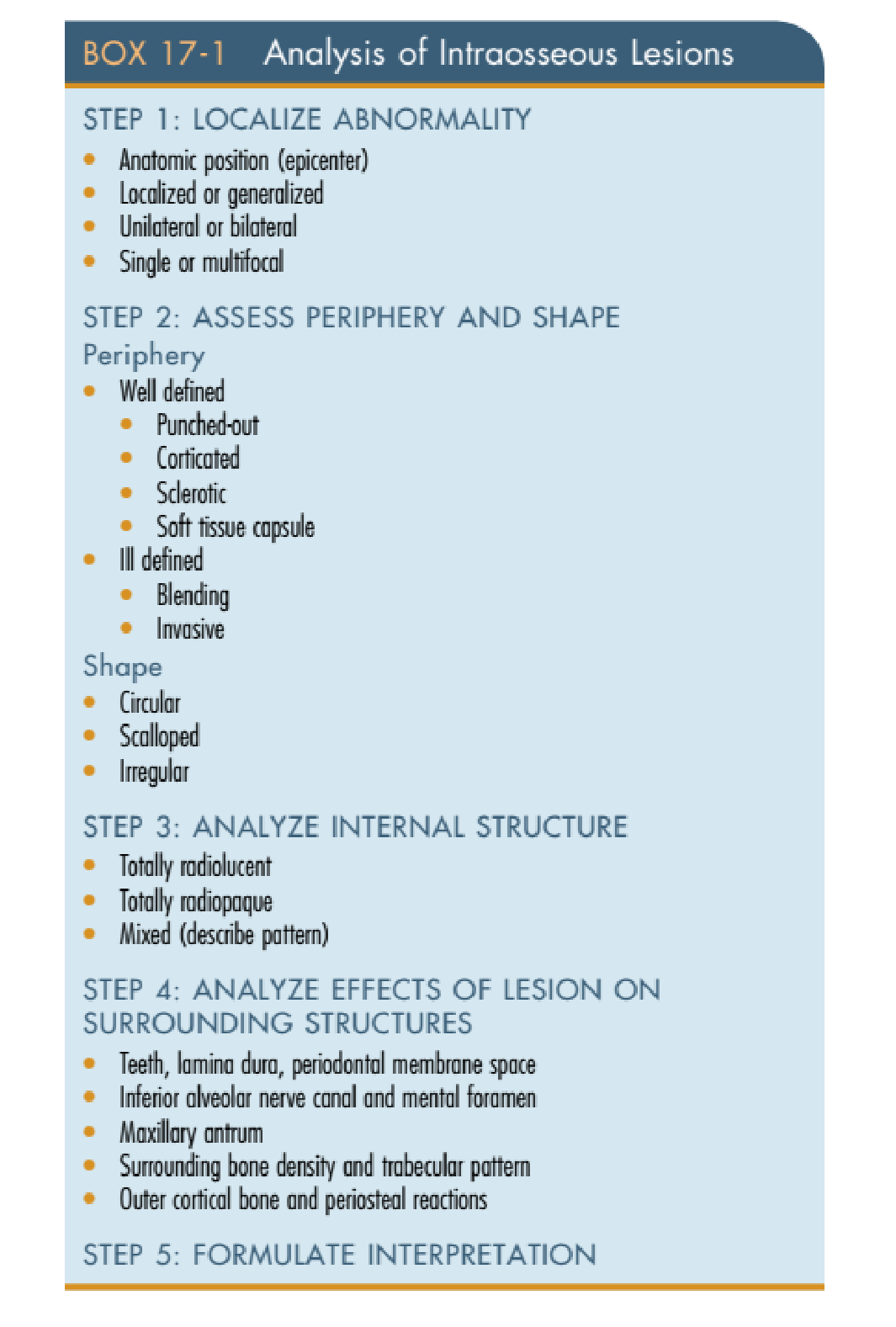
Analysis of Intraosseous Lesions
STEP 1: LOCALIZE ABNORMALITY
- Anatomic position (epicenter)
- Localized or generalized
- Unilateral or bilateral
- Single or multifocal
STEP 2: ASSESS PERIPHERY AND SHAPE
Periphery
- Well defined
- Punched-out
- Corticated
- Sclerotic
- Soft tissue capsule
- Ill defined
- Blending
- Invasive
Shape
- Circular
- Scalloped
- Irregular
Localization and Peripheral Assessment7
STEP 3: ANALYZE INTERNAL STRUCTURE
- Totally radiolucent
- Totally radiopaque
- Mixed (describe pattern)
- Mixed internal structures may contain “denticles” or amorphous masses
STEP 4: ANALYZE EFFECTS OF LESION ON SURROUNDING STRUCTURES
- Teeth, lamina dura, periodontal membrane space
- Assess for root resorption, displacement of teeth, or effacement (absence) of the lamina dura
- Inferior alveolar nerve canal and mental foramen
- Maxillary antrum
- Surrounding bone density and trabecular pattern
- Outer cortical bone and periosteal reactions
STEP 5: FORMULATE INTERPRETATION
Further Reading: White & Pharoah’s Oral Radiology 8th Ed (Chapter 18)
Diagnostic Mnemonics and Algorithms8
Surgical Sieve
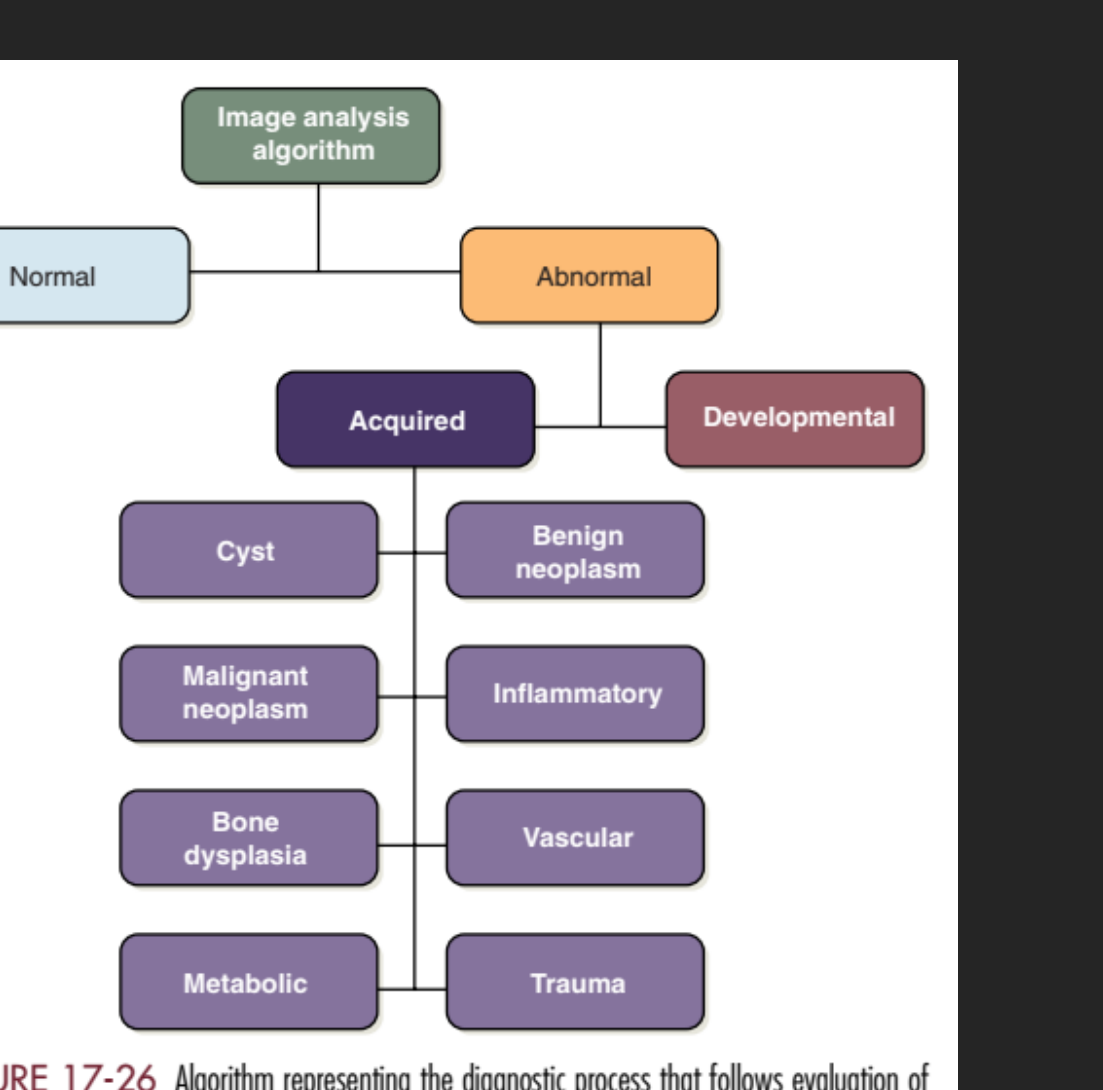
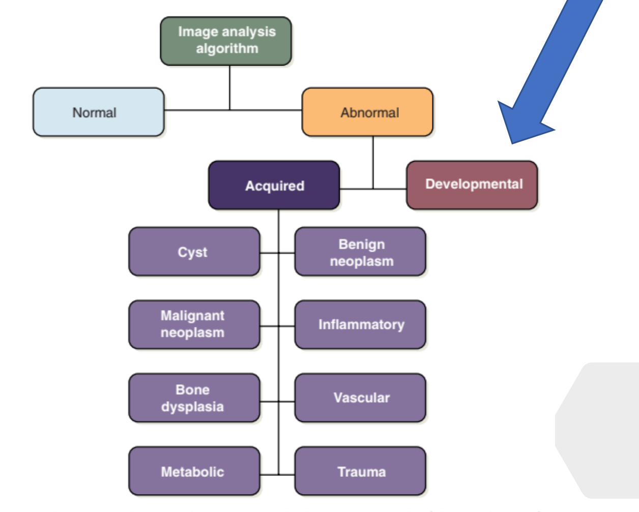
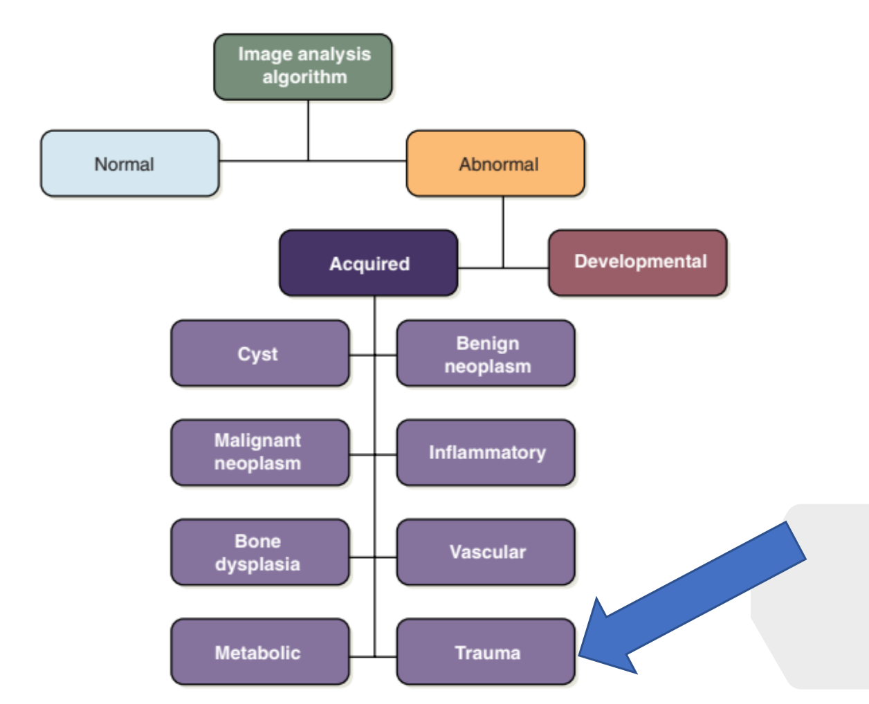
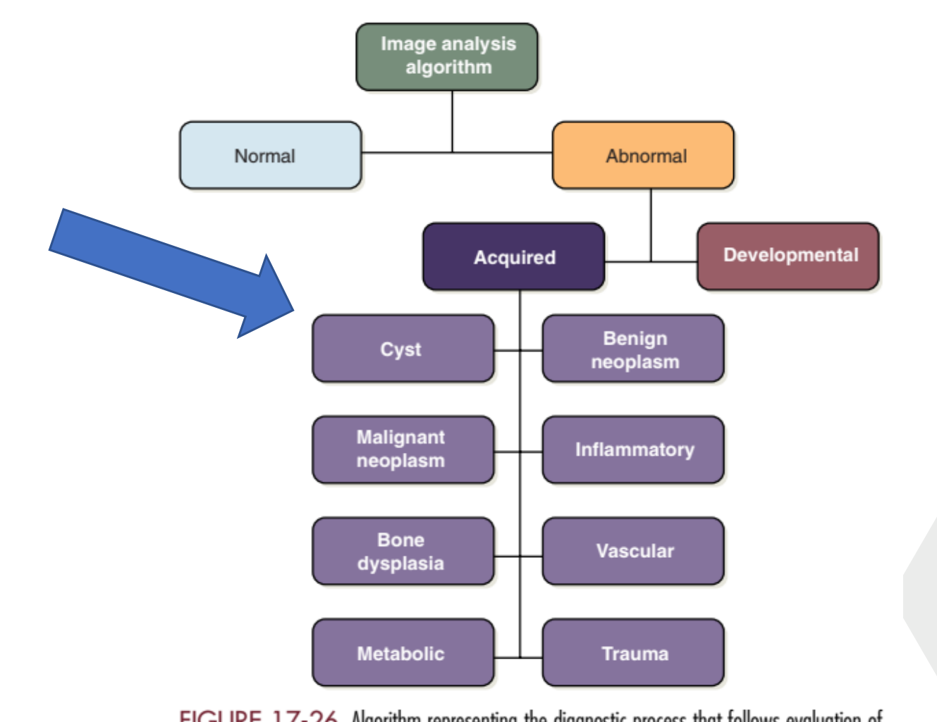
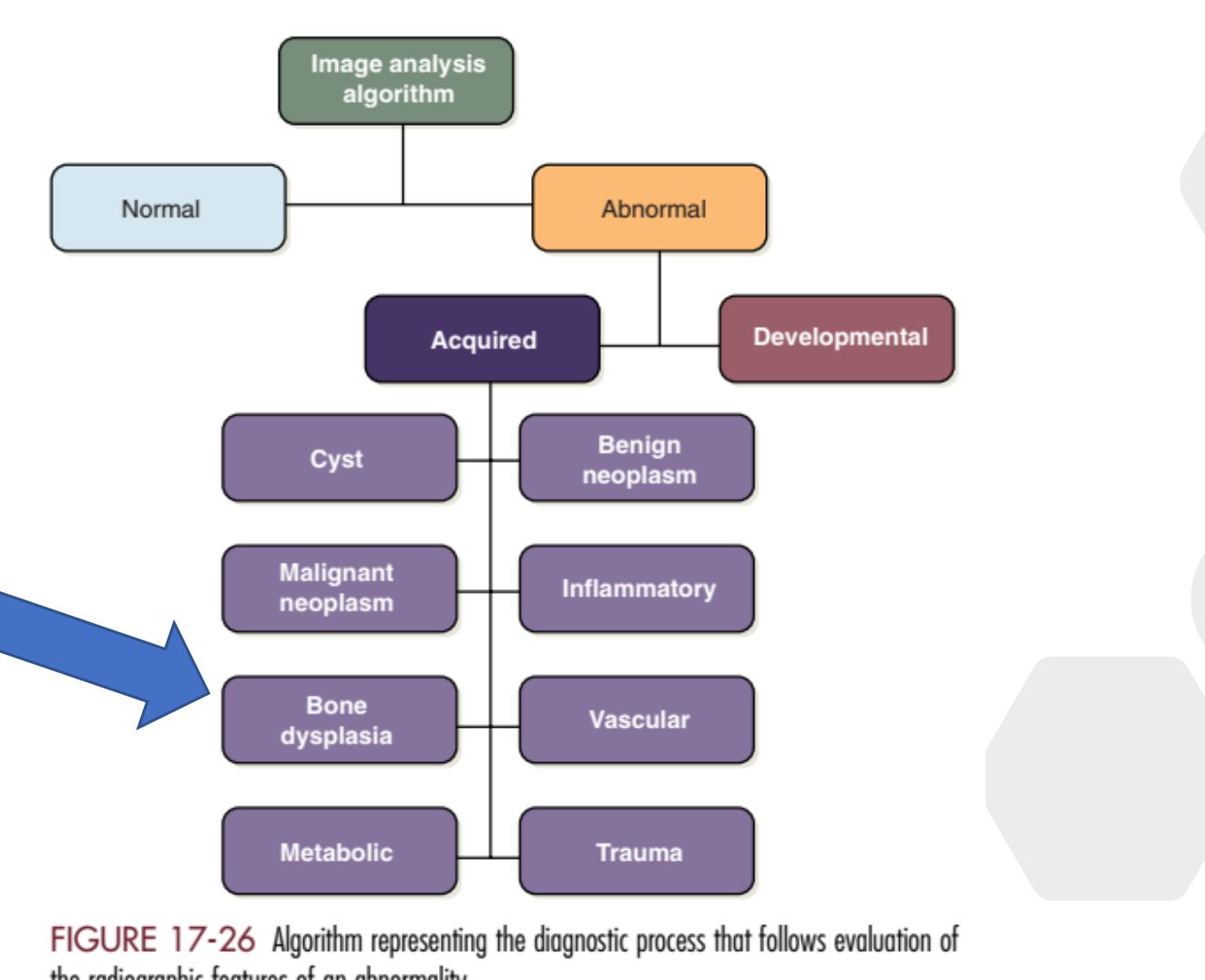
A method to categorize findings by first determining if a finding is normal or abnormal. If abnormal, decide if it is developmental or acquired. Acquired lesions are then broken down into broad categories such as inflammatory, neoplastic, or metabolic.
Differential Diagnosis
Answers should always be ordered from most likely to least likely.
5I 3-Scotland
Where “3-Scotland” relates to the three top killers in Scotland.
- I: infection
- I: inflammation
- I: immune
- I: iatrogenic
- I: idiopathic
- 1: vascular/cardiovascular
- 2: cancer
- 3: trauma
Figure 17-26 Algorithm representing the diagnostic process that follows evaluation of the radiographic features of an abnormality.
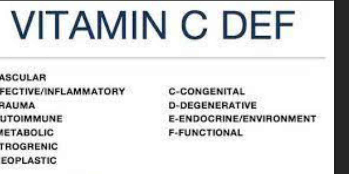
VITAMIN C DEF
- V - VASCULAR
- I - INFECTIVE/INFLAMMATORY
- T - TRAUMA
- A - AUTOIMMUNE
- M - METABOLIC
- I - IATROGENIC
- N - NEOPLASTIC
- C - CONGENITAL
- D - DEGENERATIVE
- E - ENDOCRINE/ENVIRONMENT
- F - FUNCTIONAL
 |  |
General Case Studies9
Mandibular and Maxillary Bitewing Analysis10
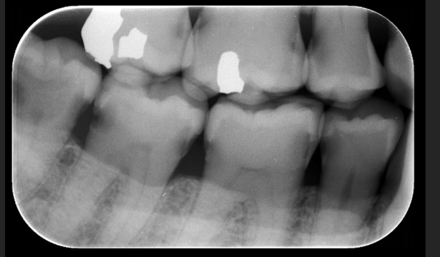
This is a bite-wing radiograph, showing the Permanent Mandibular Right First Premolar and Second Premolar and Permanent Mandibular Left First Molar, Second Premolar, and First Molar.
 |  |
 |
Normal Anatomy11
This image displays a standard PA radiographic image. It shows the Permanent Mandibular Right Second Premolar (30), First Molar (31), and Permanent Mandibular Left Second Premolar (33), First Molar (32), and Second Molar number (37). The superimposition of the permanent Mandibular Left and Right Mentangles or canines in the deep Nazian fossa at the nasal root, intercalated by the coronoid process of the right mandible. These can be seen to be normal in all corners.
There is:
-
Periodontal status? The periodontal status of the primary molar (20-30) appears normal, with no evidence of gingival or periodontal disease. The permanent Mandibular Right Second Premolar (30) and First Molar (31) and Permanent Mandibular Left Second Premolar (33), First Molar (32), and Second Molar (37) also appear normal, with no evidence of gingival or periodontal disease.
-
Restorations? The permanent Mandibular First Molar (32) has a large silver amalgam restoration in the occlusal area, with no further restorations visible on the periapical radiograph.
-
Caries? There is no radiographic evidence of caries in the permanent Mandibular Right Second Premolar (30) or First Molar (31) and Permanent Mandibular Left Second Premolar (33), First Molar (32), or Second Molar (37).
-
Resorption? There is no evidence of resorption in any of the teeth shown in the radiograph.
-
Periapical lesions? There is no evidence of periapical lesions around the roots of any of the teeth in the radiograph.
-
Other findings? The radiograph reveals the presence of a large silver amalgam restoration in the occlusal area of the permanent Mandibular First Molar (32). Additionally, there appears to be a small, well-defined radiolucency near the apices of the roots of the permanent Mandibular Third Molar (38), but it is not clear if the tooth is fully erupted or impacted.
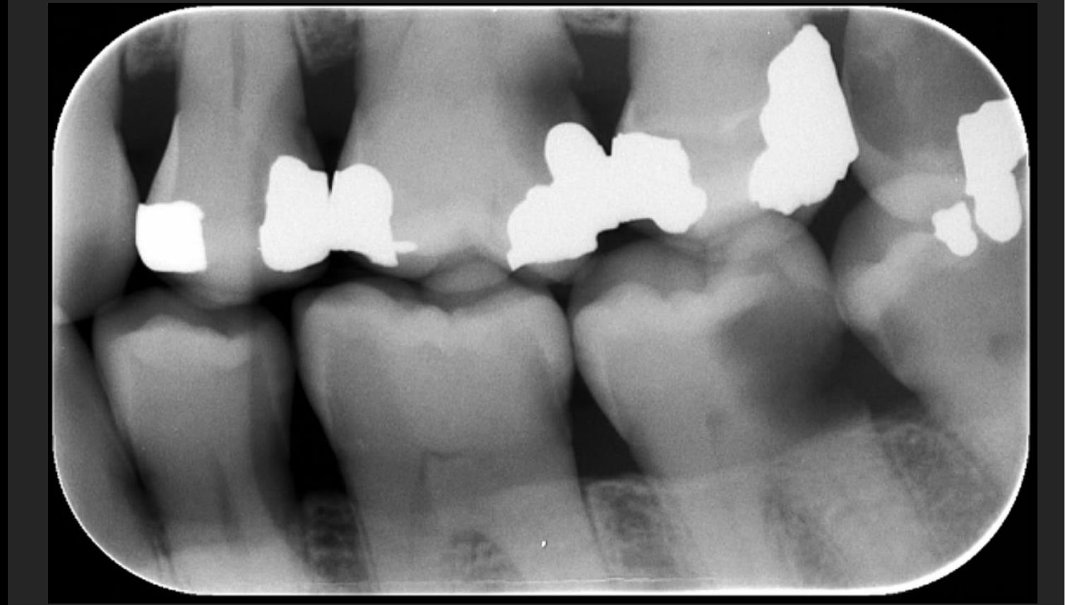
This is a bitewing radiograph, showing the maxillary posterior teeth (premolars and first molars) and mandibular posterior teeth (premolars and first molars) from the right quadrant.
Alveolar bone crest, periodontal ligament space, lamina dura, enamel, dentin, and pulp chambers are visible.
There is:
-
Periodontal status: Mild horizontal bone loss is evident, particularly around the mandibular premolars and the maxillary right canine (which appears to be the only non-molar tooth included in the field of view aside from premolars). The PDL space appears physiological.
-
Restorations: Multiple large, radiopaque restorations are visible, specifically in the maxillary right first and second premolars and the mandibular right first and second molars (or potentially first molar and canine depending on angulation). The material appears to be amalgam (metal).
-
Caries: There is evidence of carious lesions at the occlusal surfaces of both mandibular premolars, seen as radiolucent areas within the occlusal fossae.
-
Resorption: No obvious internal or external root resorption is identified.
-
Periapical lesions: None identified.
-
Other findings: The seeds or foreign material seen in the lower jaw area (superficial to the root of the mandibular right first molar) appear to be artifacts, possibly grain or debris, rather than pathological calcification. The borders of the smaller molar teeth in the background appear to be in close apposition.
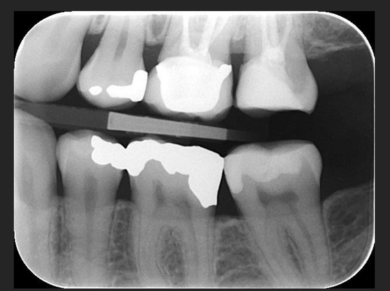
Case Study: Left Bitewing (Teeth 23-27, 37-33)
- Findings: Mild periodontal bone loss between 26 and 27.
- Restorations noted in 24 (amalgam), 26 (PFM crown), 27 (composite), 37 (composite), 36 (amalgam), and 35 (amalgam).
- No caries or root resorption noted.
Case Study: Right and Left Bitewings with Processing Artifacts
- Artifacts: Dark and light lines caused by another film sitting on top of the phosphor plate, preventing or allowing exposure to ambient light, which reduces contrast.
- Findings: Mild bone loss at 47 and 48. Multiple amalgam restorations.
- Extensive carious lesions noted across multiple teeth (17, 16, 15, 25, 26, 28, 38, 37, 36, 45, 46, 47, 48).
- Large lesions extending into pulp chambers suggest the need for periapical radiographs.
Intraoral Periapical Radiograph Findings121314151617
This is an intraoral periapical radiograph (IOPA), showing teeth 21, 22, 23, 24, and 34.
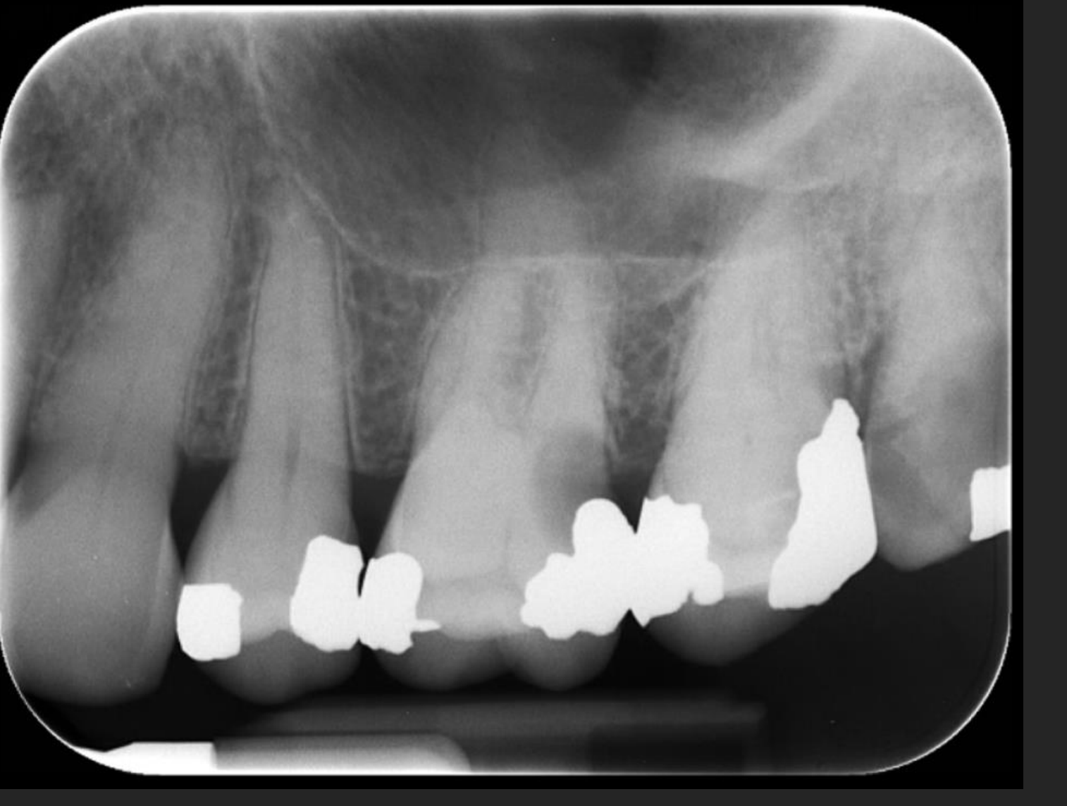
Case Study: Left Maxillary Periapical (23-28)
- Normal Anatomy: Floor of the left maxillary sinus, antral air space, and zygomatic process of the maxilla.
- Findings: Blunting of 22 apex (root resorption). 26 and 28 show coronal lucencies (caries).
There is:
- Periodontal status?
- Restorations? (Bonus: material?)
- Caries?
- Resorption?
- Periapical lesions? (not applicable for BW)
- Other findings?
This is a type of radiograph, showing the insert tooth numbers.
There is:
- Periodontal status?
- Restorations? (Bonus: material?)
- Caries?
- Resorption?
- Periapical lesions? (not applicable for BW)
- Other findings?
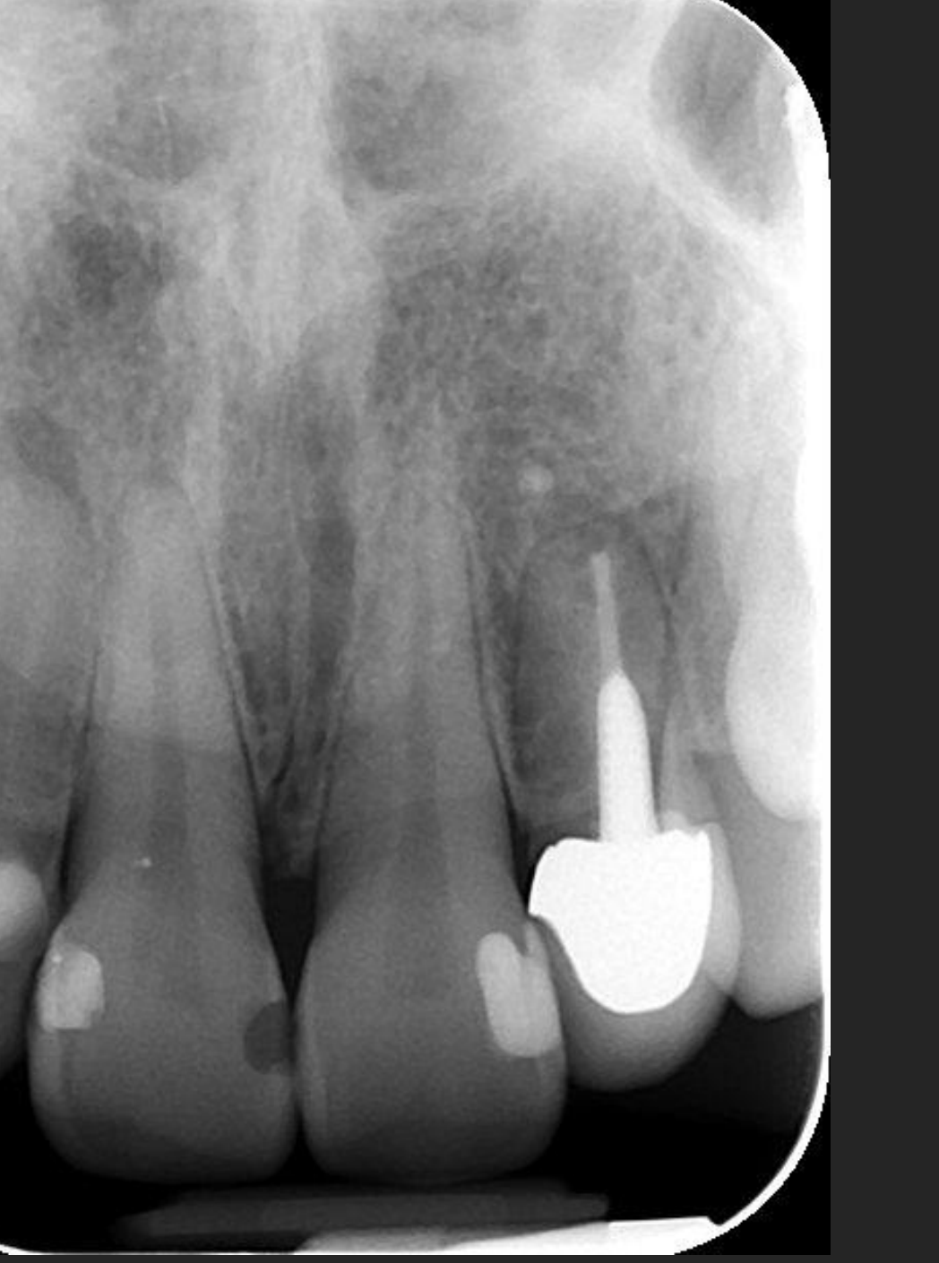
This is an intraoral periapical radiograph, showing the mandibular right incisors and canine (teeth #24, #25, #26, and the developing #27).
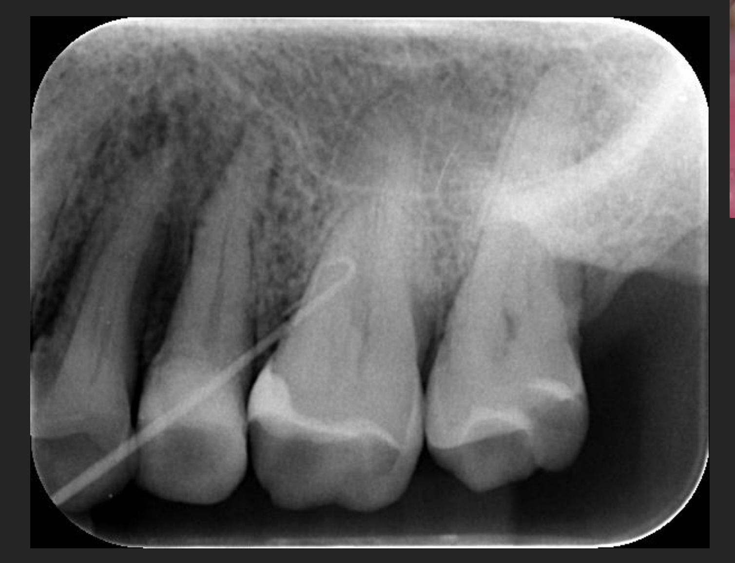
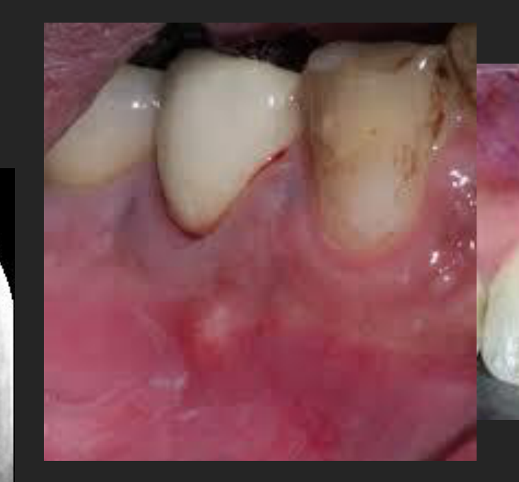
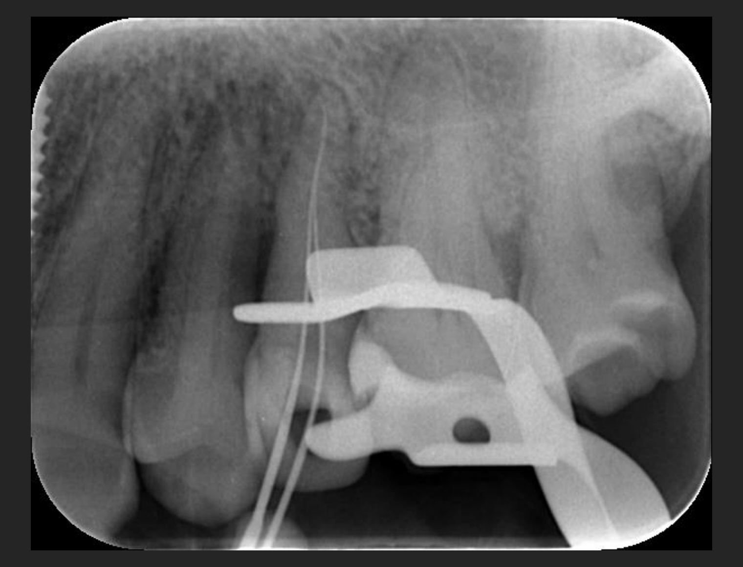
Case Study: Left Maxillary Periapical (24-27) with Draining Sinus
- Findings: Moderate to severe vertical bone loss at 24. PDL widening at 25.
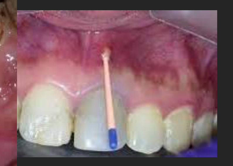
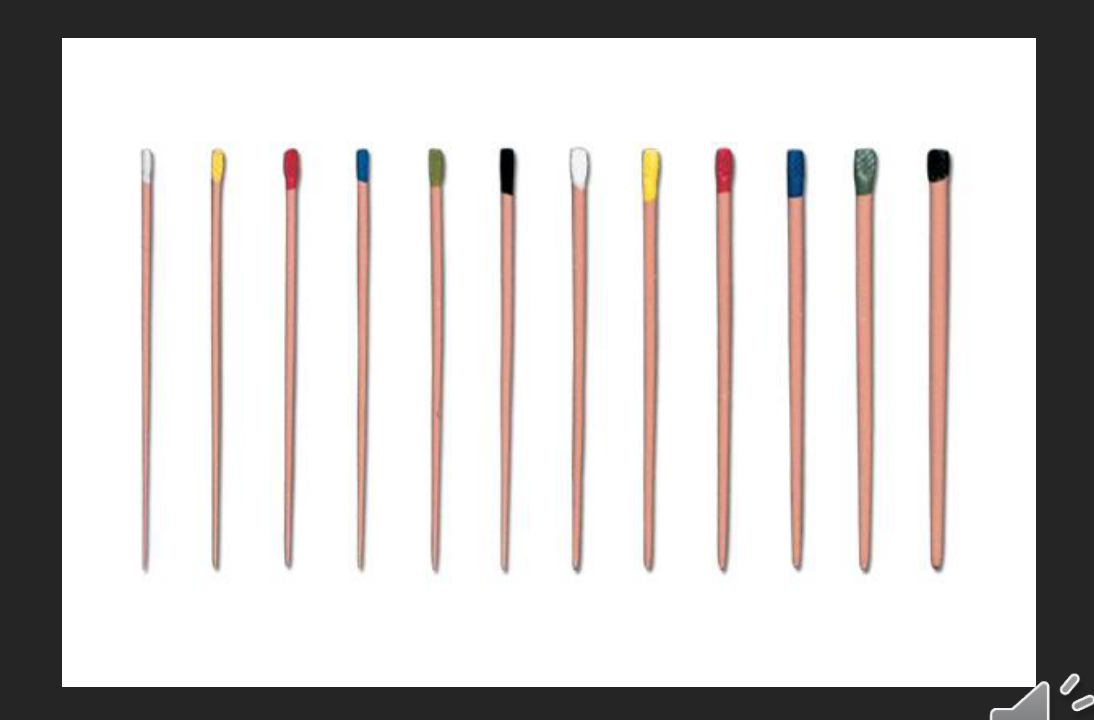
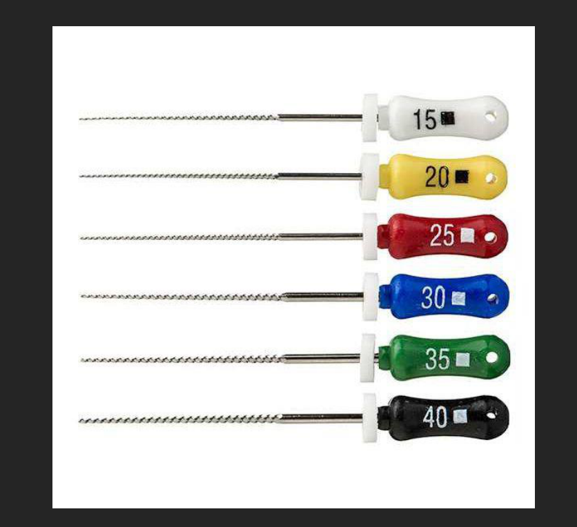
- Clinical Note: A radiopaque structure (gutta-percha) is used to trace a draining sinus tract to identify the source of infection.
There is:
- Periodontal status?
- Restorations? (Bonus: material?)
- Caries?
- Resorption?
- Periapical lesions? (not applicable for BW)
- Other findings?
Case Study: Anterior Maxillary Periapical (12-22)
- Normal Anatomy: Incisive foramen and canal, anterior nasal spine, floor of the nasal cavity (diamond-shaped), and intermaxillary suture.
- Findings: 11 mesial lucency (Differential: lucent restorative material, lost restoration, or caries).
- 12 periapical lucency consistent with apical periodontitis. 22 is endodontically treated with extruded material.
This is an intraoral periapical radiograph, showing the teeth numbered 22, 23, 24, and 25.
The image exhibits the following:
- Periodontal status: There is generalized horizontal alveolar bone loss, with bone crest levels approximately 3-5mm below the CEJ. The right of the crest of the second molar (tooth #24) shows first-degree furcation involvement.
- Restorations: There is evidence of a radiopaque restorative material (amalgam filling) in the right lingual portion of the right maxillary first premolar (#24).
- Caries: No obvious signs of caries are detected.
- Resorption: No signs of external or internal resorption.
- Periapical lesions: No evidence of periapical radiolucencies.
- Other findings: The right mandibular canine (#32) shows a significantly wider crown than the normal-root ratio, suggesting an anatomical variation or ectopic indentation.
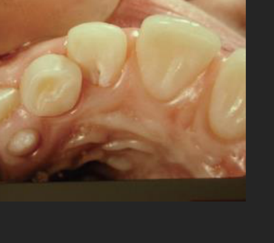
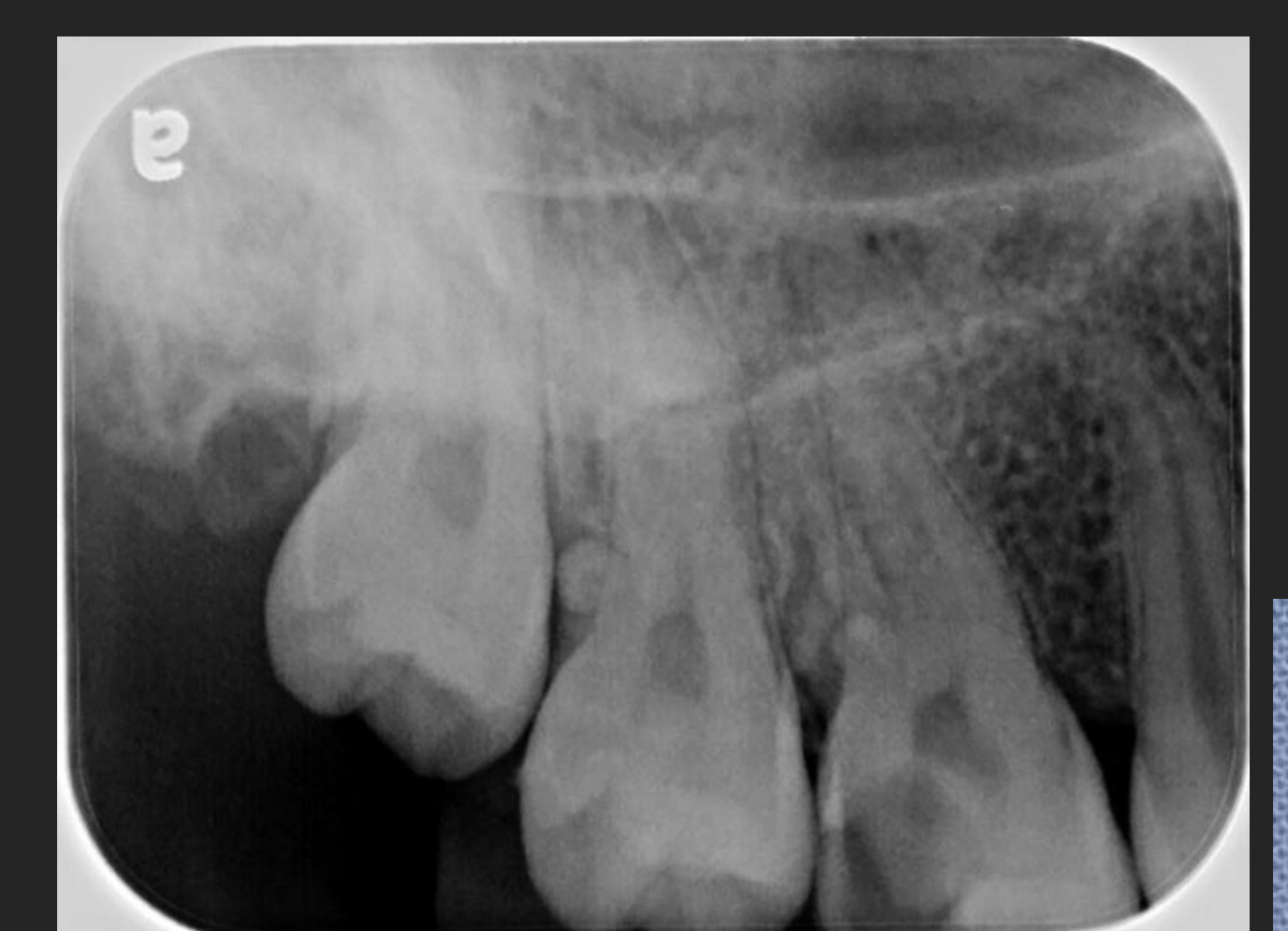
Case Study: Developmental Anomalies (Dens Invaginatus)
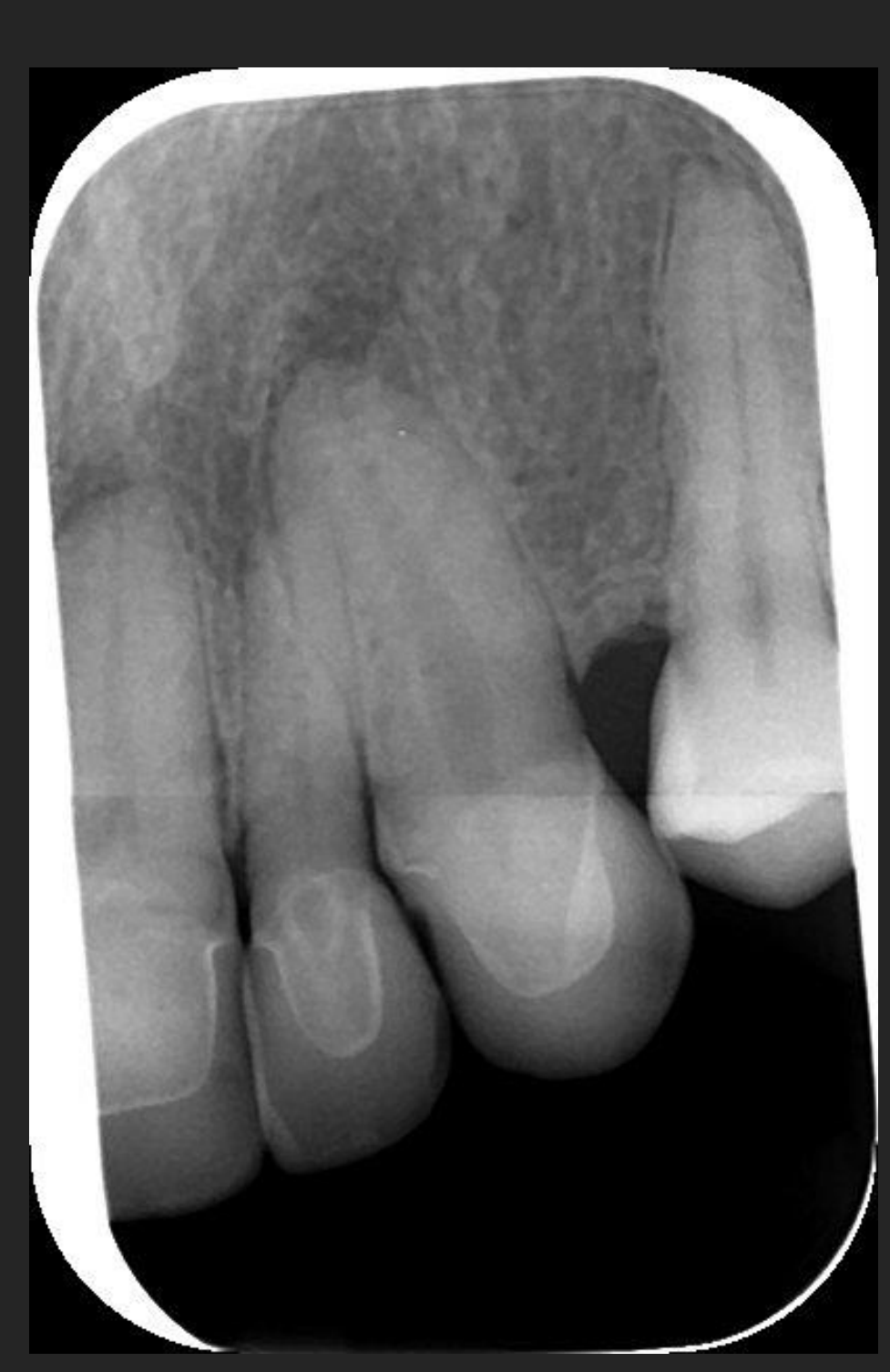
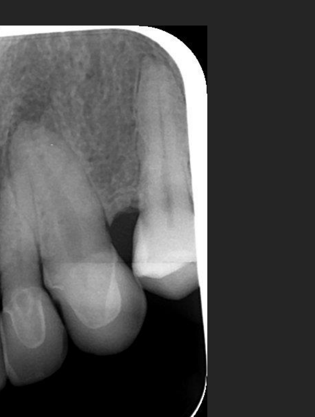
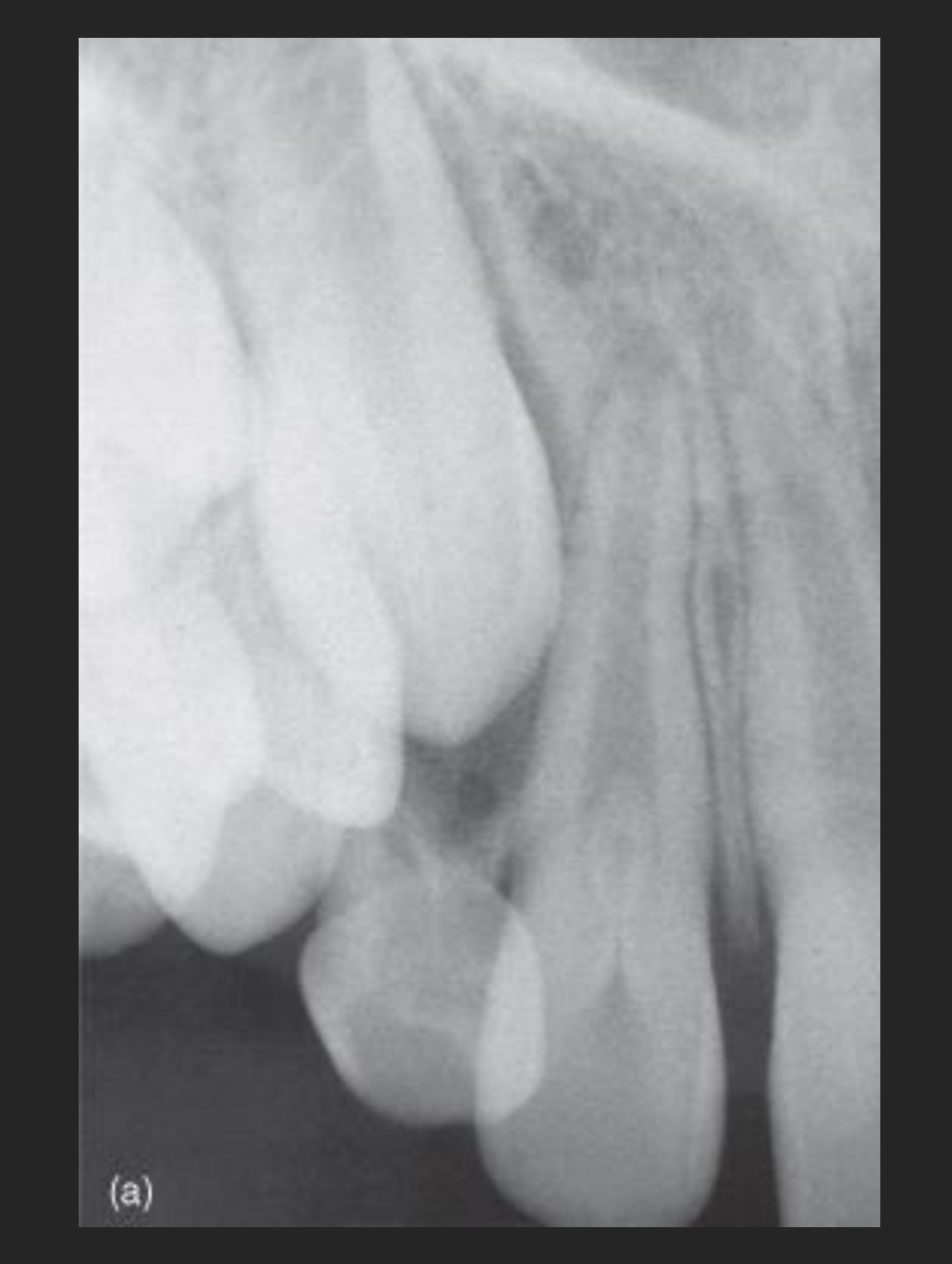
- Findings: Periapical of 12 and 13. Enamel density within the 12 root canal with a central lucency.
- Clinical Note: This “infolding” makes the tooth prone to bacterial ingress and pulp necrosis.
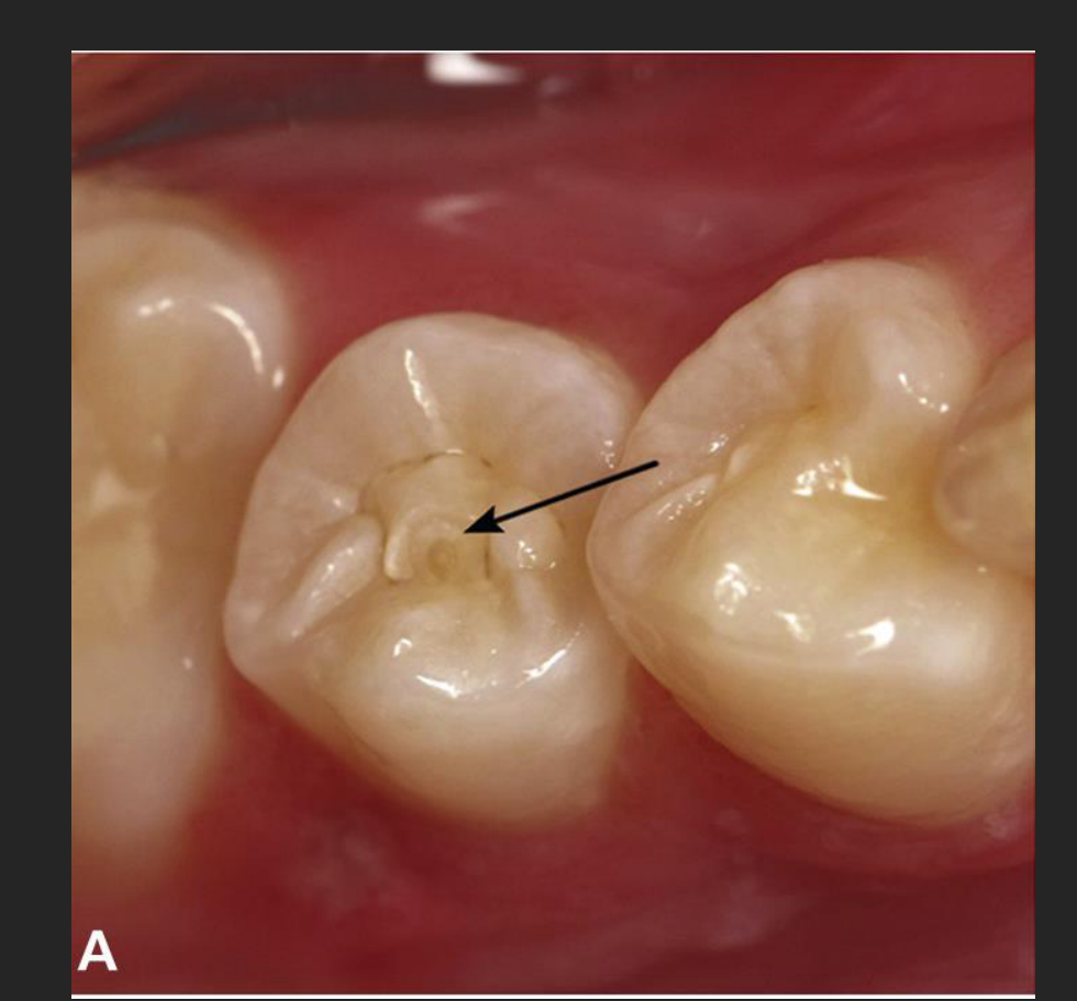
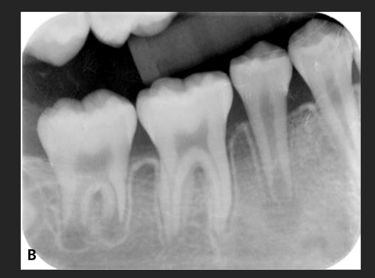
Case Study: Developmental Anomalies (Dens Evaginatus)
- Findings: Mandibular periapical (44-47). 45 shows a periapical lucency with adjacent sclerosis.
- Cause: An “outfolding” of enamel/dentine (tubercle) that broke off, exposing pulp tissue and leading to necrosis and halted root development.
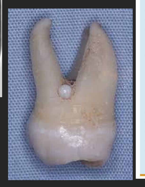
Case Study: Enamel Pearl
- Findings: Well-defined circular opacity of enamel/dentine density at the cervical region of 16 and 17.
- Clinical Note: Often associated with localized periodontal disease.
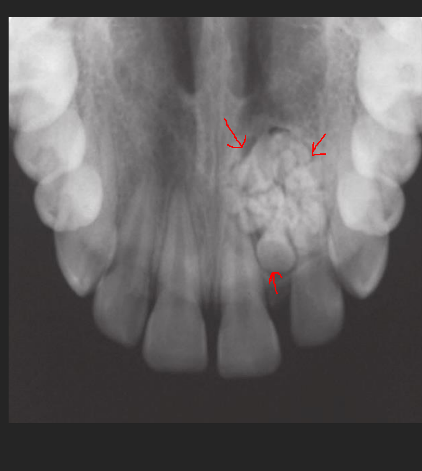
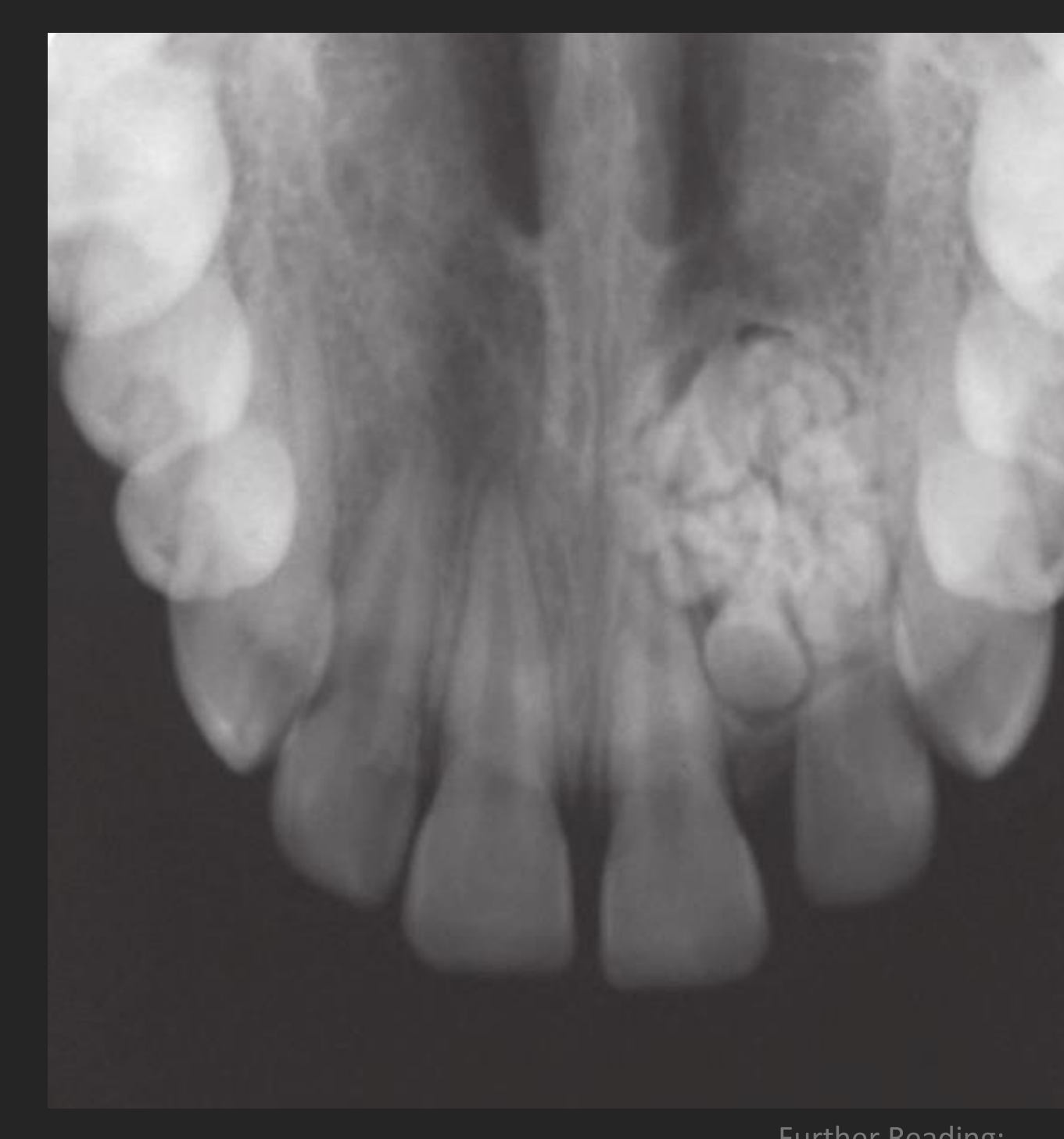
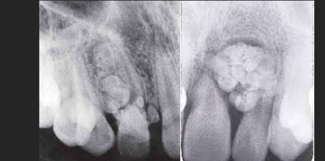
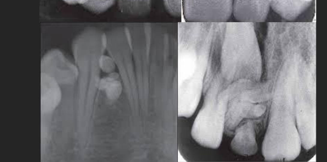
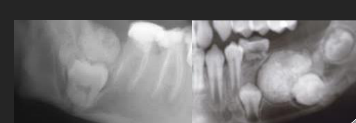
Case Study: Odontoma
- Findings: Maxillary occlusal radiograph showing a lesion between 12 and 22. Well-defined corticated border with internal “denticles” (small teeth).
- Types: Compound (anterior, small denticles) and Complex (posterior, amorphous mass).
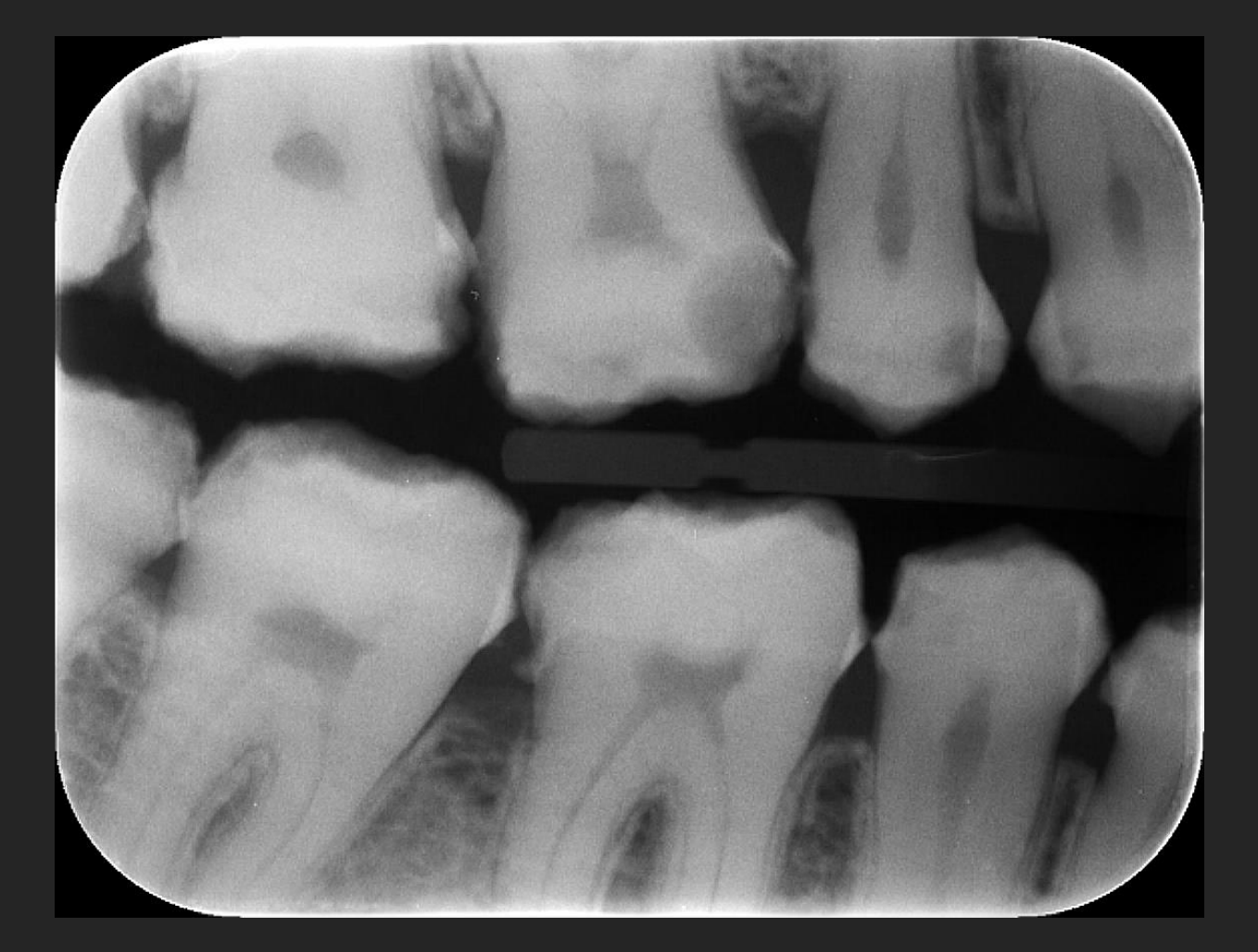
Case Study: Amelogenesis Imperfecta
- Findings: Bitewings showing generalized thin, malformed enamel on all teeth.
- Clinical Note: Enamel chips away under function, which can be mistaken for caries.
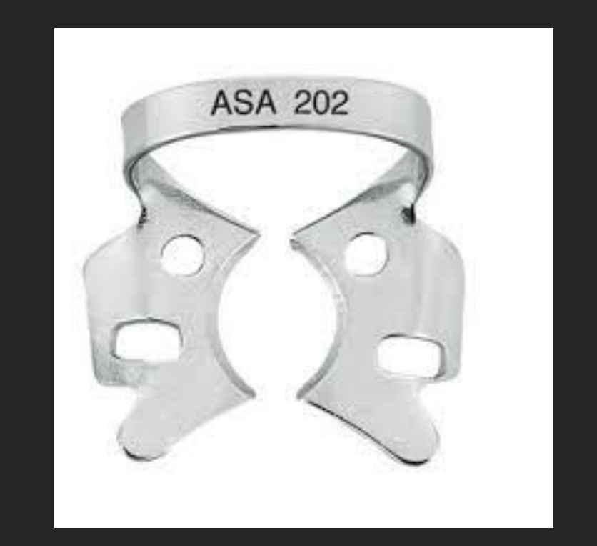
ASA 202 — one endo smoke evacuation, dual angle
 |  |  |
 |  |  |
 |  |  |
 |  |
Diagnostic Frameworks and Image Analysis
| Image analysis algorithm | |
| Normal | Abnormal |
| Developmental | |
| Acquired | |
| Cyst | Benign neoplasm |
| Malignant neoplasm | Inflammatory |
| Bone dysplasia | Vascular |
| Metabolic | Trauma |
White and Pharoah’s
ORAL RADIOLOGY
Principles and Interpretation
Image Analysis Algorithm Categories18192021
8th EDITION
ELSEVIER
Sanjay M. Mallya Ernest W.N. Lam
Further Reading: White & Pharoah’s Oral Radiology 8th Ed (Chapter 21)
 |  |  |
 |  |  |
 |  |
Detailed Lesion Analysis Criteria22
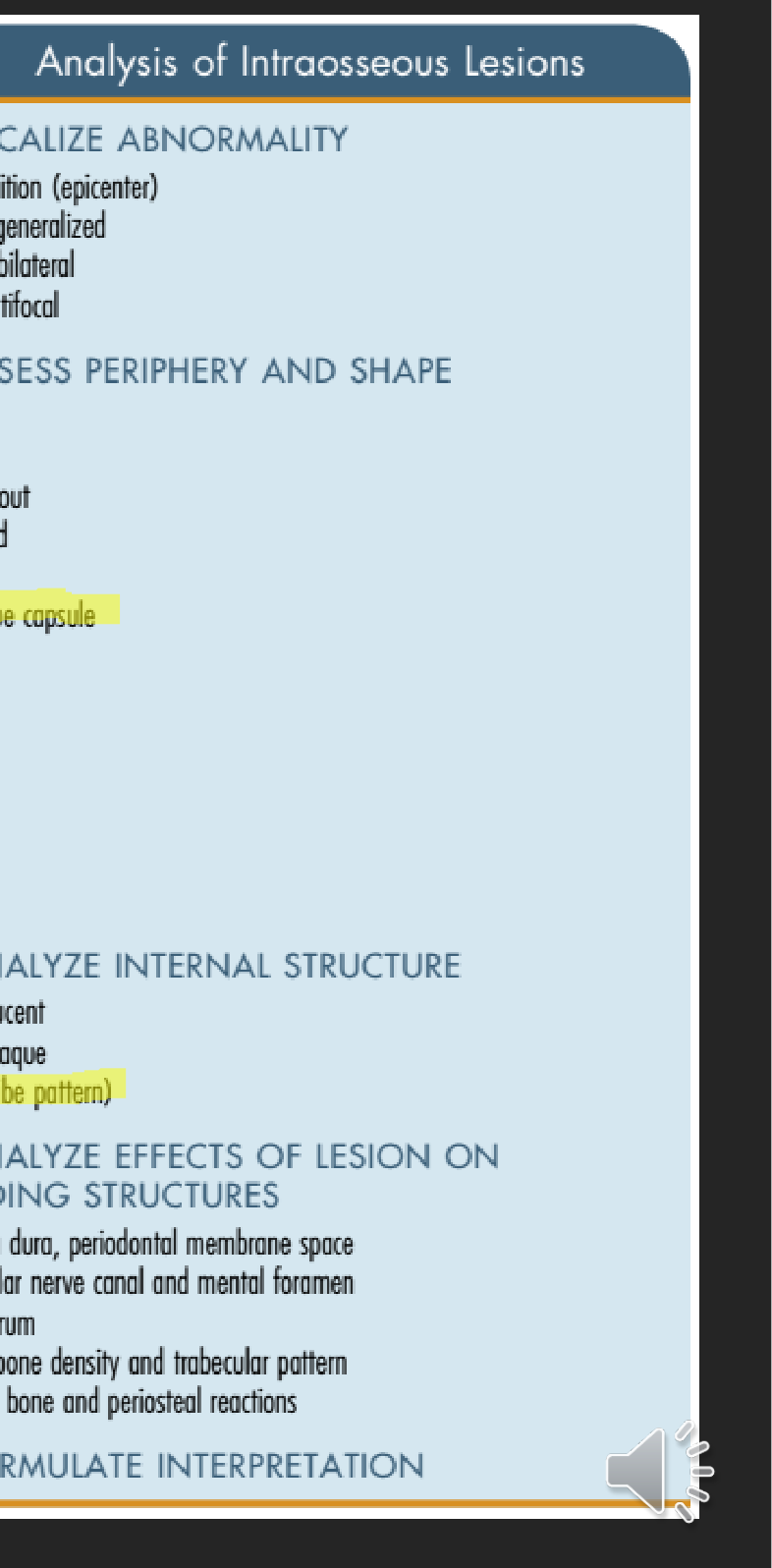
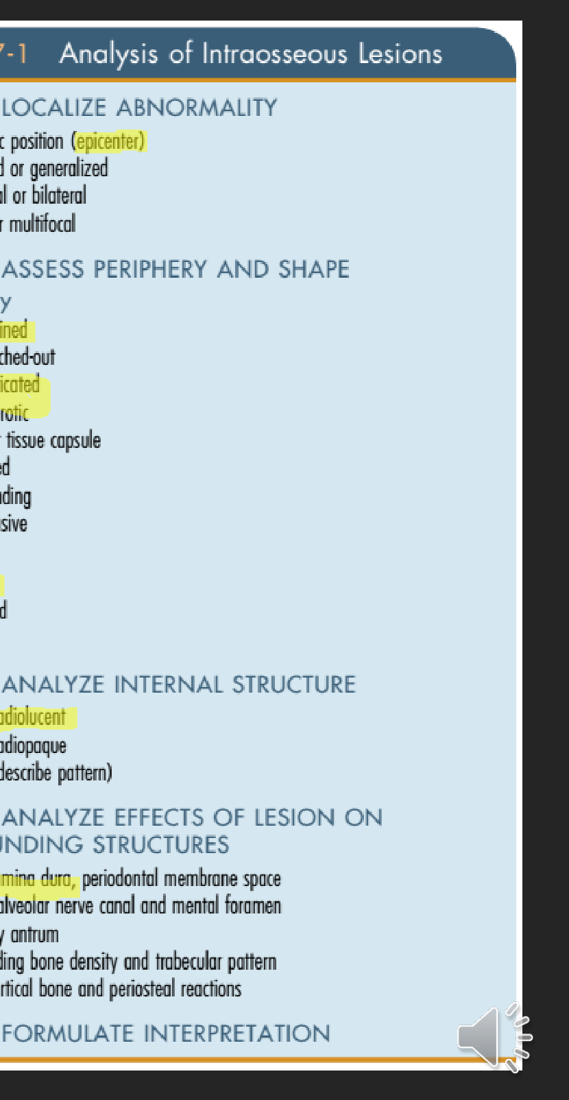
BOX 17-1 Analysis of Intraosseous Lesions
STEP 1: LOCALIZE ABNORMALITY
- Anatomic position (epicenter)
- Localized or generalized
- Unilateral or bilateral
- Single or multifocal
STEP 2: ASSESS PERIPHERY AND SHAPE
Periphery
- Well defined
- Punched-out
- Corticated
- Sclerotic
- Soft tissue capsule (highlighted)
- Ill defined
- Blending
- Invasive
Shape
- Circular
- Scalloped
- Irregular
STEP 3: ANALYZE INTERNAL STRUCTURE
- Totally radiolucent
- Totally radiopaque
- Mixed (describe pattern) (highlighted)
STEP 4: ANALYZE EFFECTS OF LESION ON SURROUNDING STRUCTURES
- Teeth, lamina dura, periodontal membrane space
- Inferior alveolar nerve canal and mental foramen
- Maxillary antrum
- Surrounding bone density and trabecular pattern
- Outer cortical bone and periosteal reactions
STEP 5: FORMULATE INTERPRETATION
 |  |
References and Further Reading
Further Reading:
Literature and Clinical Guidelines2324
DOI: 10.17096/jiufd.52886
Further Reading:
DOI: 10.1186/1750-1172-2-17
 |  |  |
 |  |  |
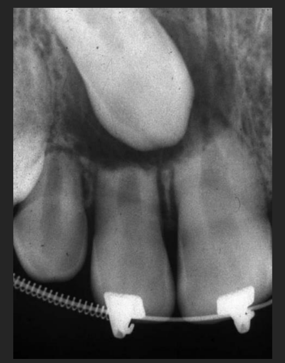
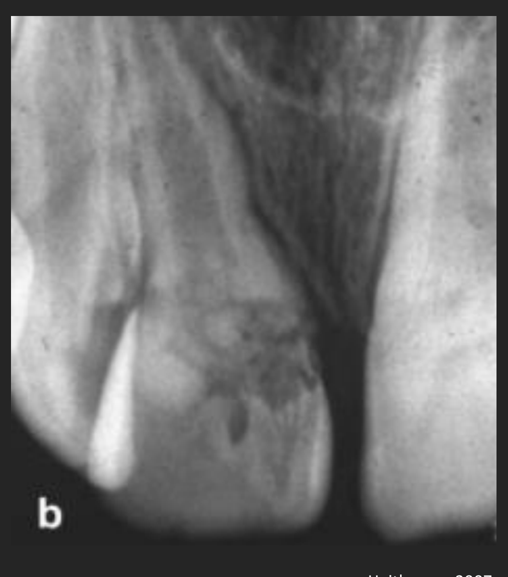
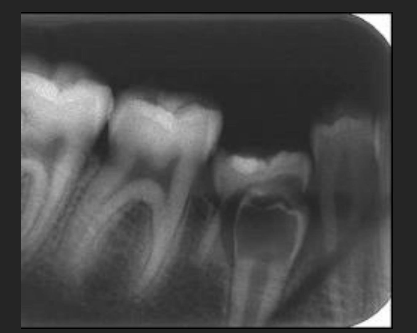
Resorption2526272829303132
Further Reading: Heithersay GS. Management of Tooth Resorption. Aust Dent J. 2007; 52:105-121
https://doi.org/10.1111/j.1834-7819.2007.tb00519.x
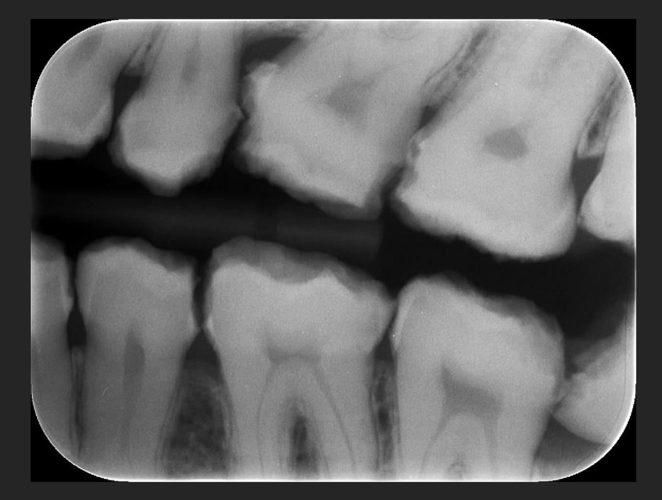
Pre-eruptive Intrachronal Resorption
Large coronal lucency in an unerupted tooth (Case: tooth 45).
Invasive Cervical Root Resorption
Irregular coronal lucency (Case: tooth 11).
Pressure Resorption
Case study of an ectopic canine (13) causing resorption of the 12 root.
FIGURE 17-26 Algorithm representing the diagnostic process that follows evaluation of the radiographic features of an abnormality.
Further Reading:
2020 IADT Guidelines for the Evaluation and Management of Traumatic Dental Injuries https://www.iadt-dentaltrauma.org/for-professionals.html
Von Arx & Bosshardt, 2016
 |  |  |
 |  |  |
 |
Advanced Diagnostic Tools
Image analysis algorithm33
- Normal
- Abnormal
- Acquired Cyst
- Malignant neoplasm
- Bone dysplasia
- Metabolic
- Benign neoplasm
- Inflammatory
- Vascular
- Trauma
- Developmental
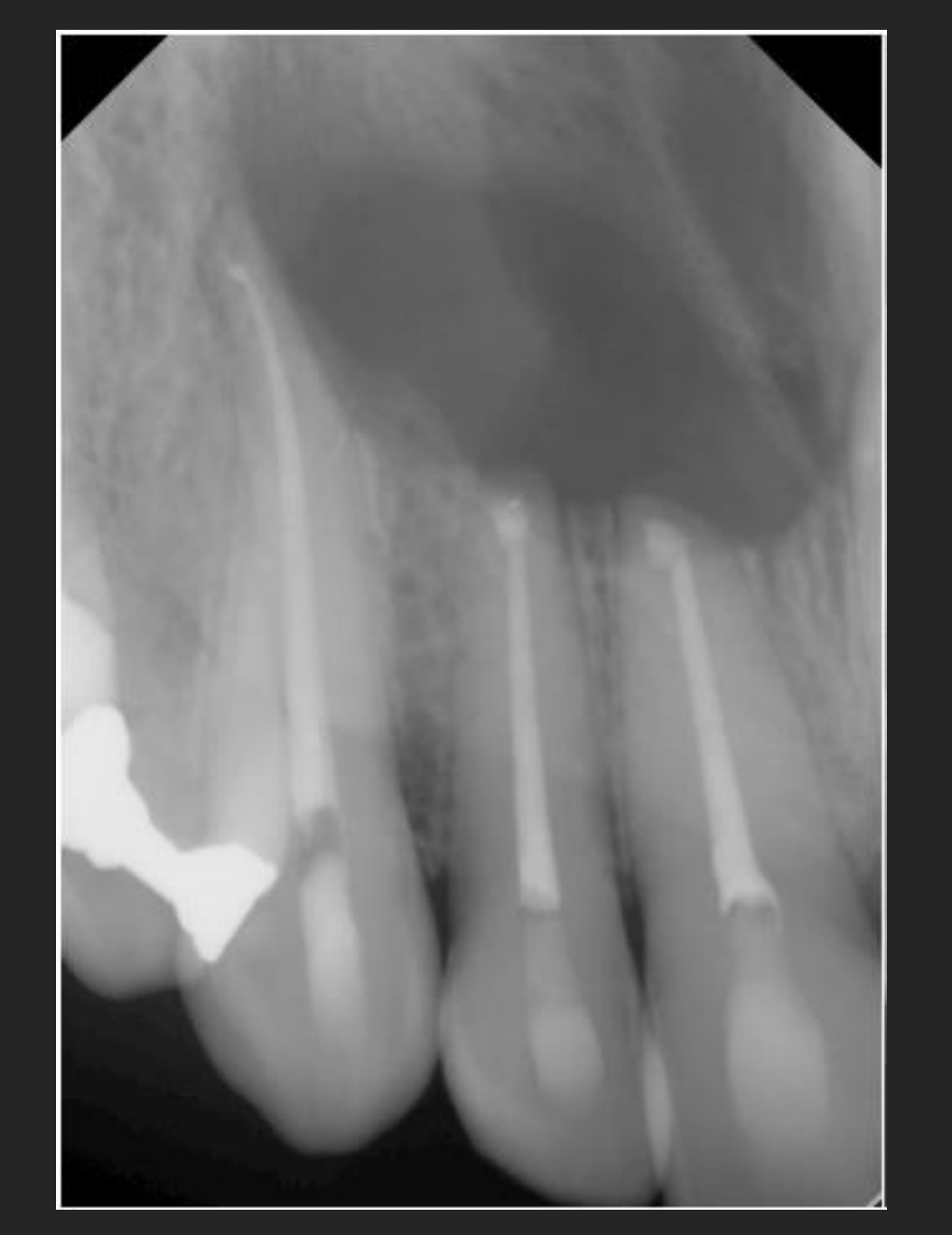
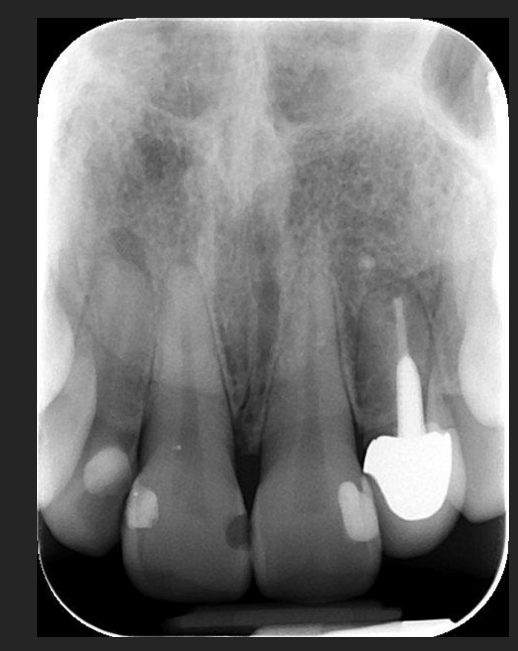
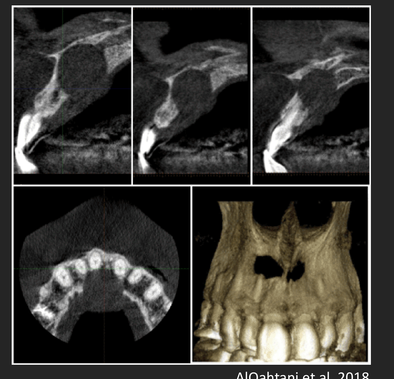
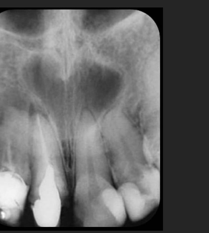
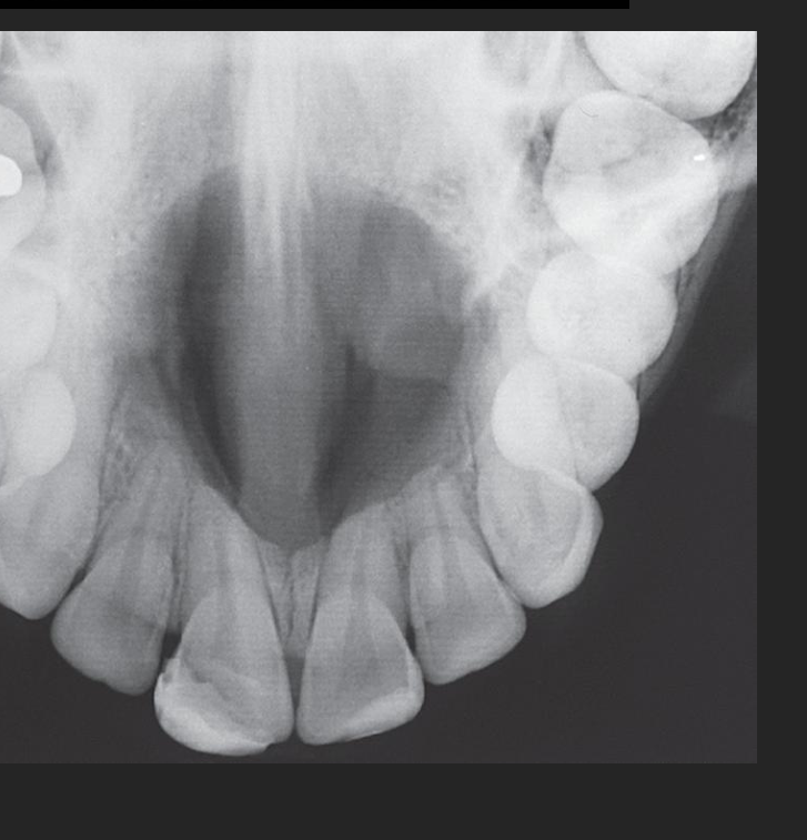
Case Study: Nasopalatine Duct Cyst vs. Apical Periodontitis
- A lesion in the anterior maxilla was initially misdiagnosed as inflammatory, leading to unnecessary root canal treatments.
- Inflammatory lesions have a “teardrop” shape centered on the apex, whereas this cyst was at right angles to the roots and centered on the incisive foramen.
- Cone Beam CT confirmed it was a Nasopalatine Duct Cyst, appearing heart-shaped due to the nasal spine.
 |  |
Oral Radiology Principles34353637
White and Pharoah’s ORAL RADIOLOGY Principles and Interpretation 8th EDITION Sanjay M. Mallya Ernest W.N. Lam ELSEVIER
Further Reading: White & Pharoah’s Oral Radiology 8th Ed (Chapter 23)
Further Reading: http://dx.doi.org/10.1016/j.path.2016.10.006
- Normal
- Abnormal
- Cyst
- Maligant neoplasm
- Bone dysplasia
- Inflammatory
- Metabolic
- Vascular
- Trauma
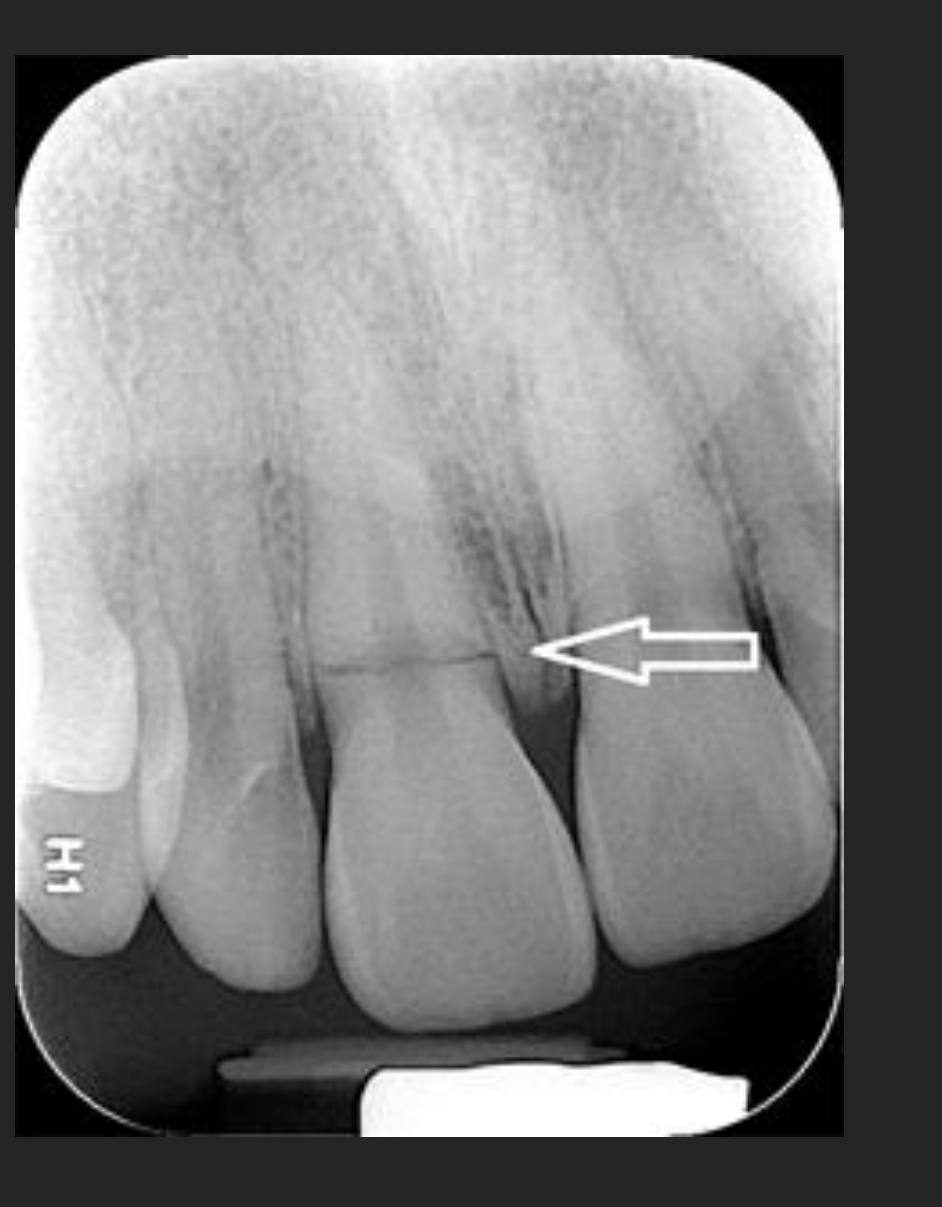
- Horizontal root fractures appear as lucent lines (e.g., tooth 11).
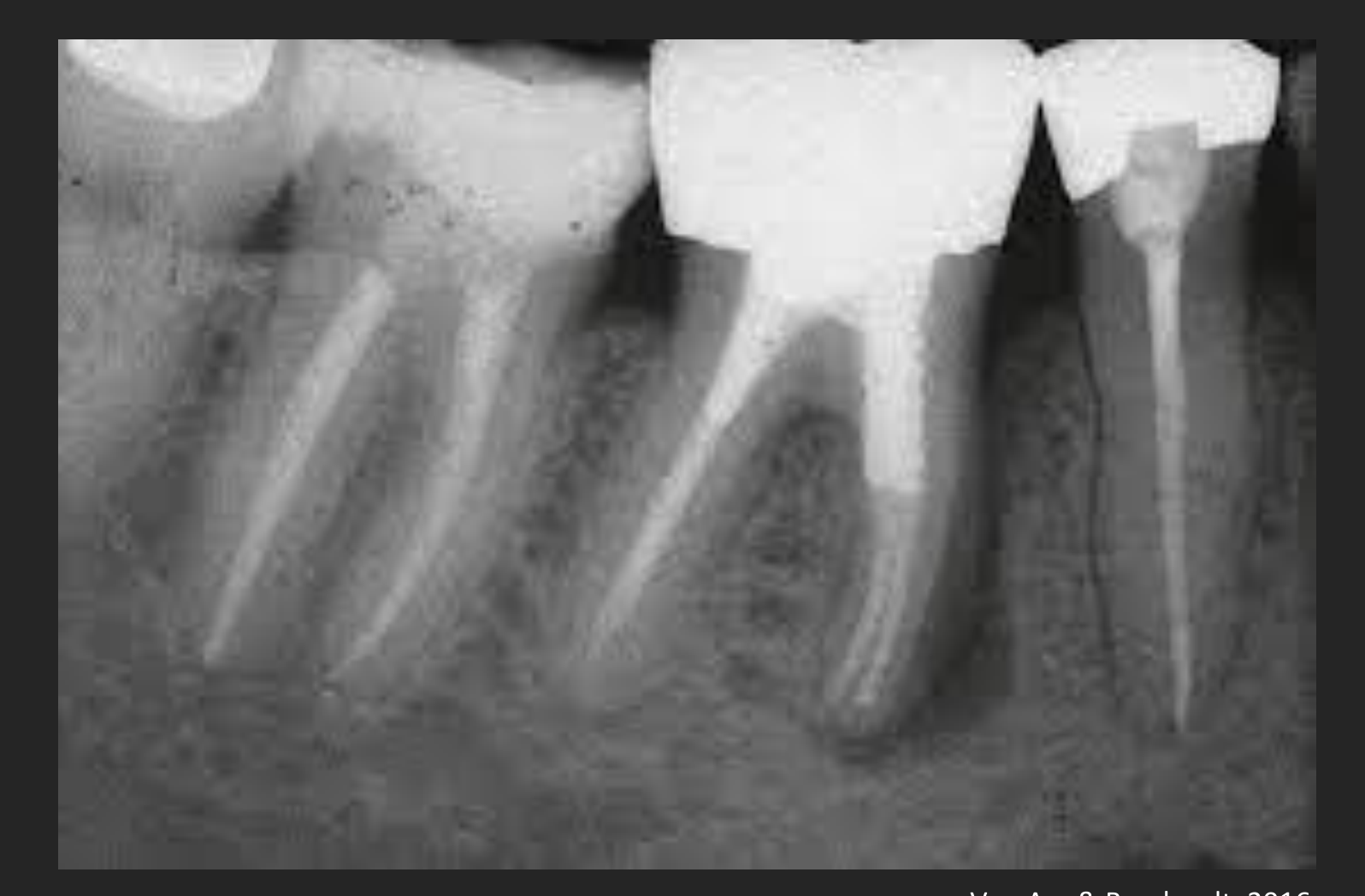
- Vertical root fractures often present with narrow, focal vertical bone loss and adjacent sclerosis (e.g., tooth 46).
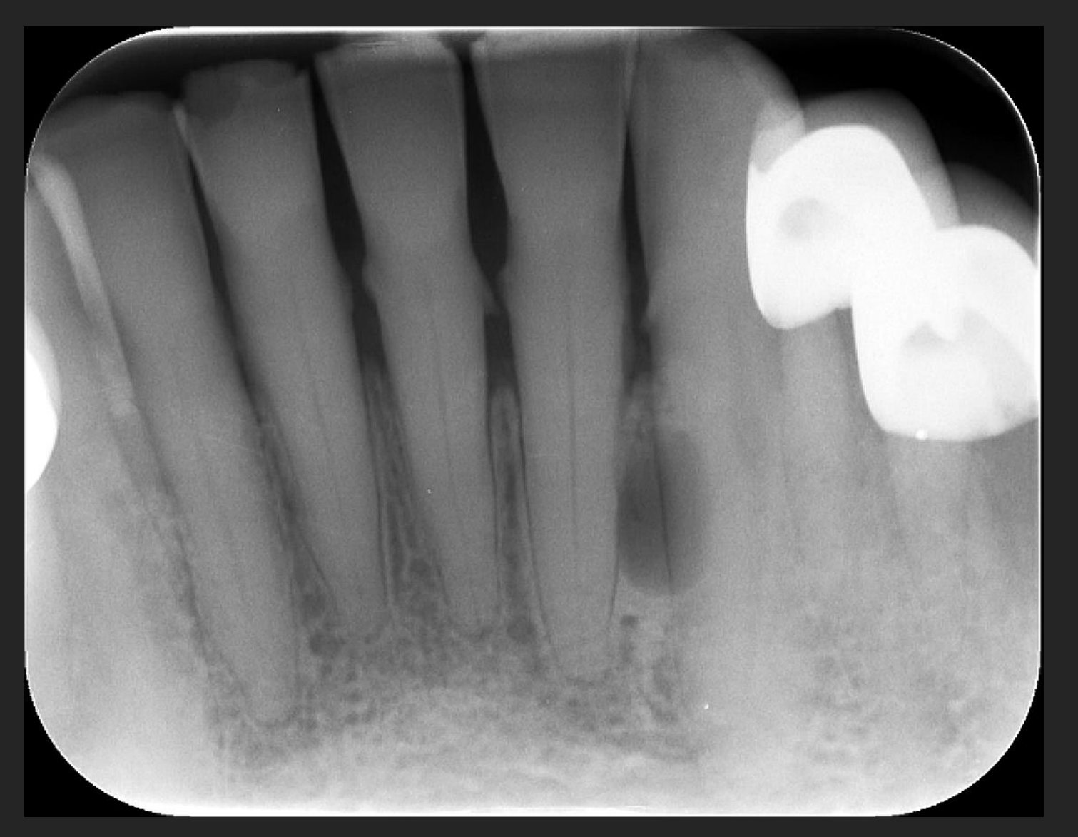
- Cysts are fluid-filled lesions with a membranous lining; for example, a lateral periodontal cyst is centered at mid-root with an intact PDL but effacement of the lamina dura.
White and Pharoah’s ORAL RADIOLOGY Principles and Interpretation 8th Edition Sanjay M. Mallya Ernest W.N. Lam ELSIEVIER Further Reading: White & Pharoah’s Oral Radiology 8th Ed (Chapter 25)
 |  |  |
 |  |  |
 |  |  |
Summary of Intraosseous Analysis3839
 |  |  |
 |  | 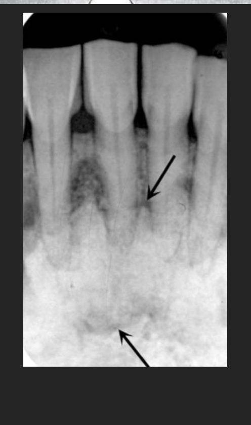 |
Box 17-1: Analysis of Intraosseous Lesions40
STEP 1: LOCALIZE ABNORMALITY
- Anatomic position (epicenter)
- Localized or generalized
- Unilateral or bilateral
- Single or multifocal
STEP 2: ASSESS PERIPHERY AND SHAPE Periphery
- Well defined
- Punched-out
- Corticated
- Sclerotic
- Soft tissue capsule
- Ill defined
- Blending
- Invasive Shape
- Circular
- Scalloped
- Irregular
STEP 3: ANALYZE INTERNAL STRUCTURE
- Totally radiolucent
- Totally radiopaque
- Mixed (describe pattern)
STEP 4: ANALYZE EFFECTS OF LESION ON SURROUNDING STRUCTURES
- Teeth, lamina dura, periodontal membrane space
- Inferior alveolar nerve canal and mental foramen
- Maxillary antrum
- Surrounding bone density and trabecular pattern
- Outer cortical bone and periosteal reactions
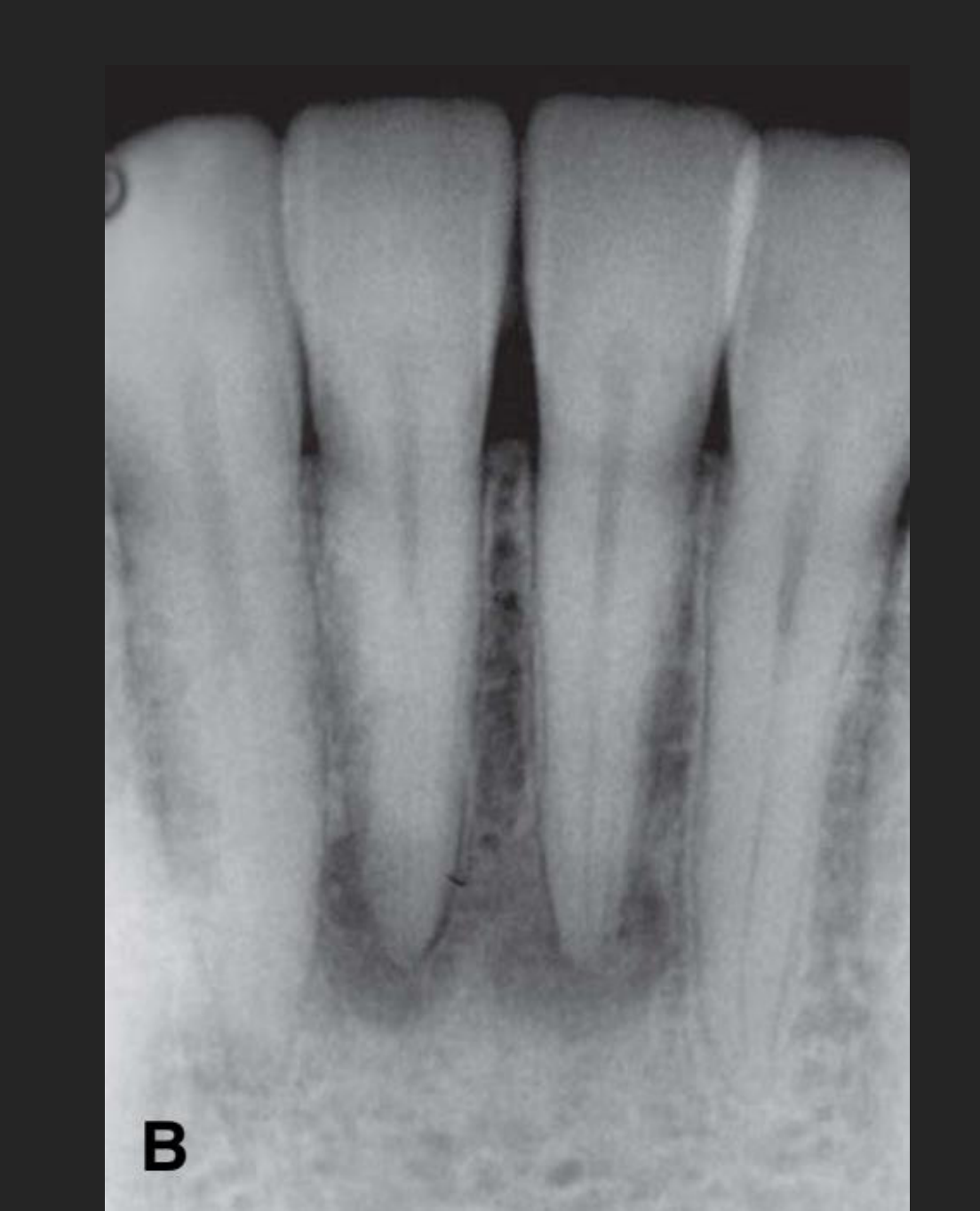
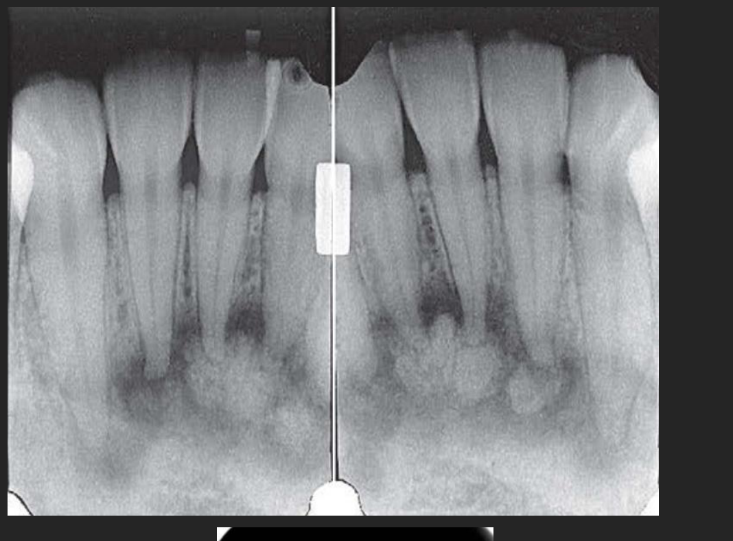
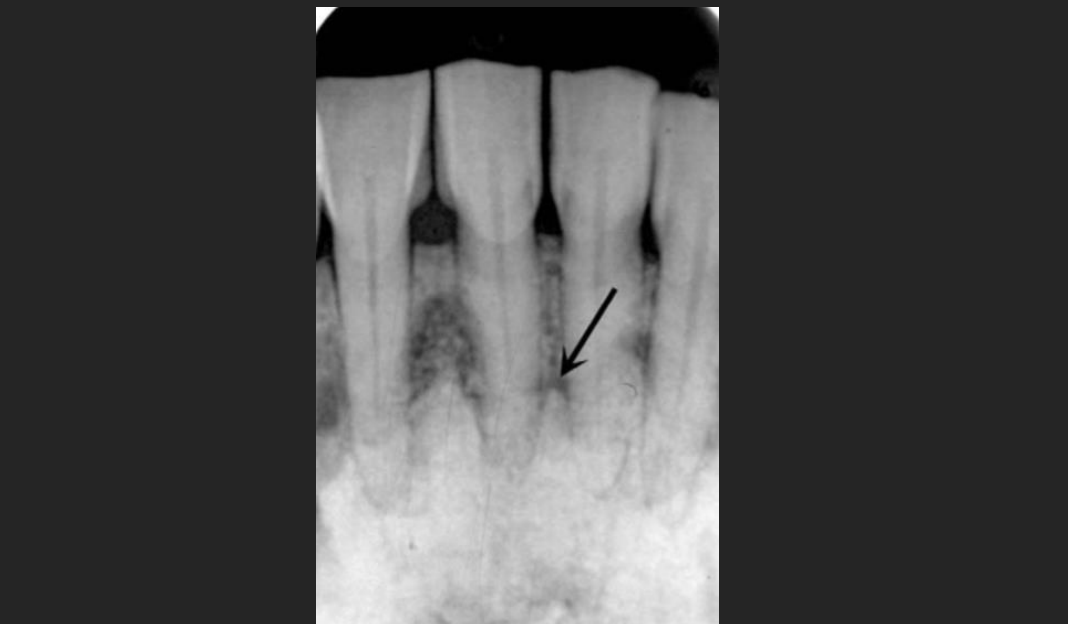
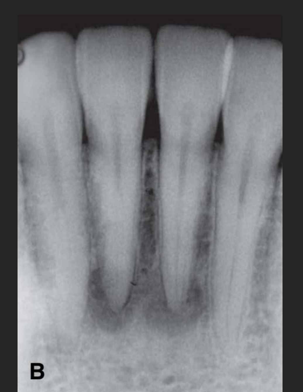
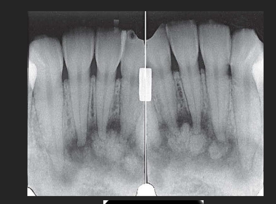
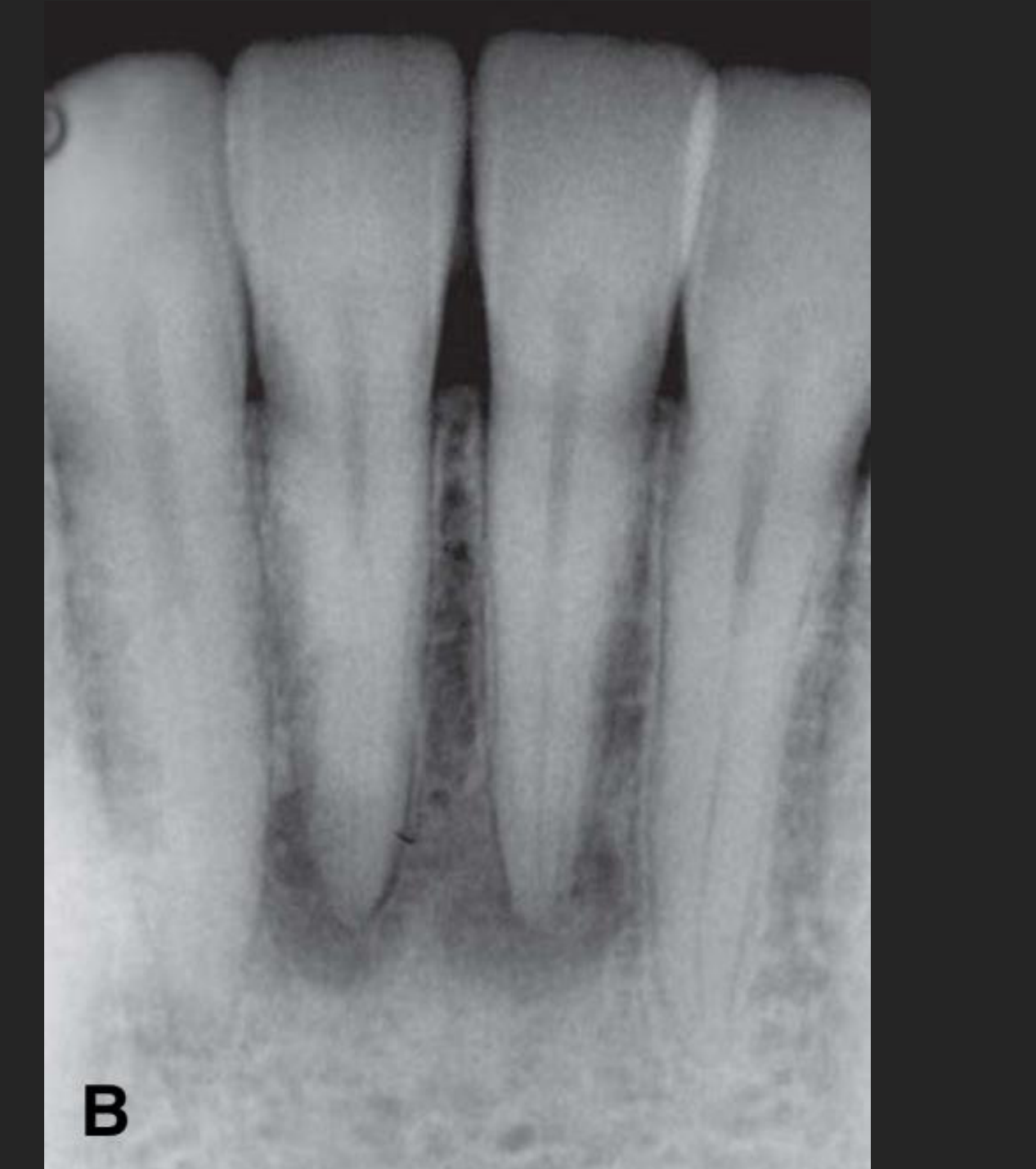
Case Study: Cemento-Osseous Dysplasia (COD)
- Phases: Early (radiolucent/hypodense, often misdiagnosed as apical periodontitis), Intermediate (mixed density), and Late (radiopaque clumps).
- Key Diagnostic Feature: Teeth are vital (pulp test positive) and the PDL space remains intact, unlike inflammatory lesions.
- Clinical Risk: These lesions are avascular; unnecessary endodontic treatment can lead to serious infection and bone necrosis.
STEP 5: FORMULATE INTERPRETATION
Clinical Challenge Case
Challenge Case41
Case Presentation
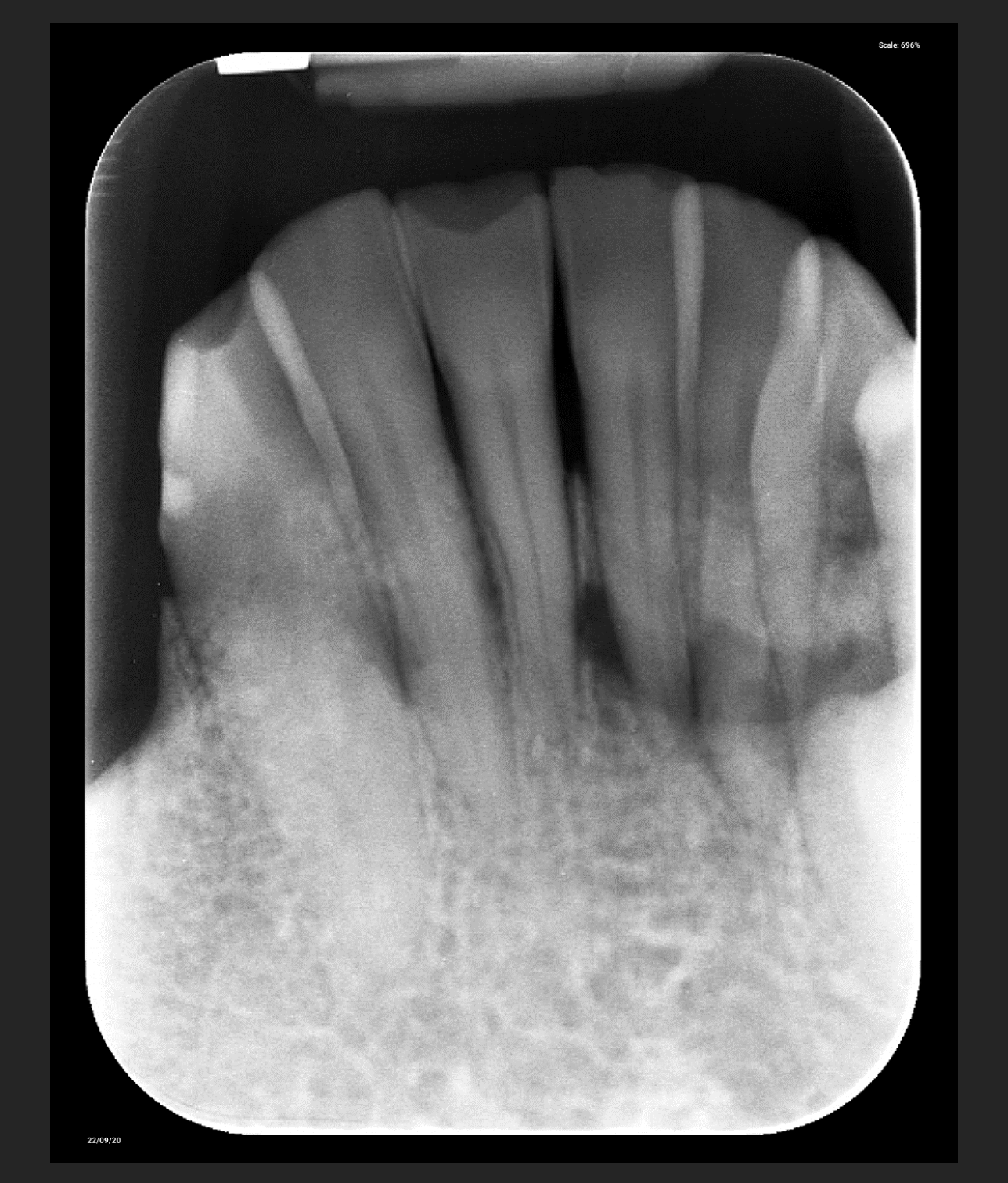
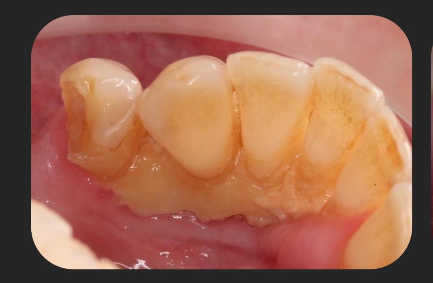
- Mandibular anterior periapical showing irregular bone loss at the mid-root level of 33 to 43.
- The alveolar crest remains intact, ruling out standard periodontal disease.
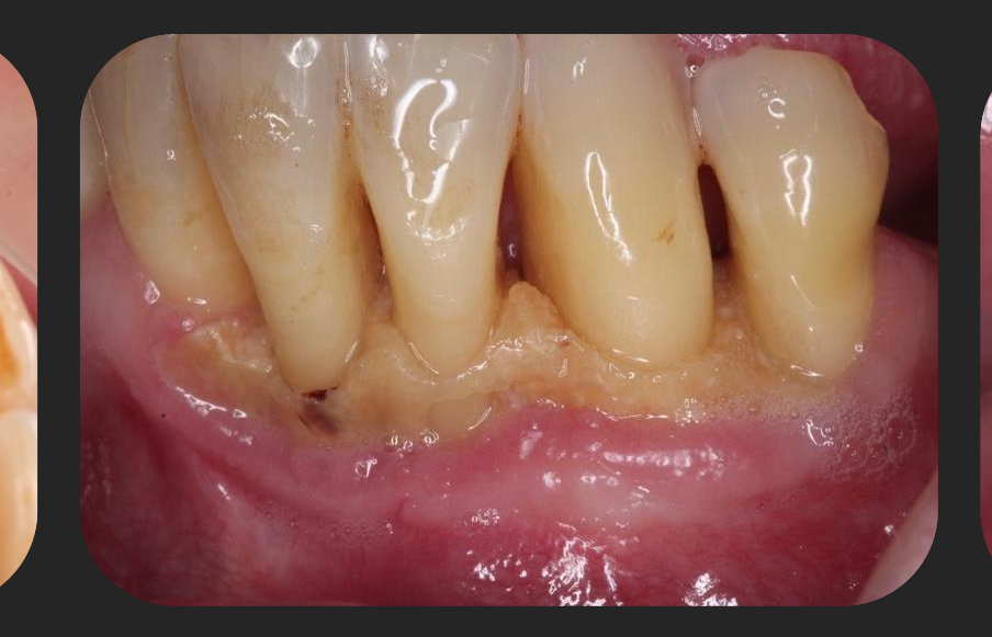
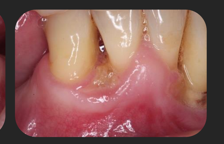
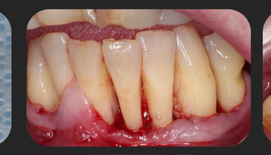
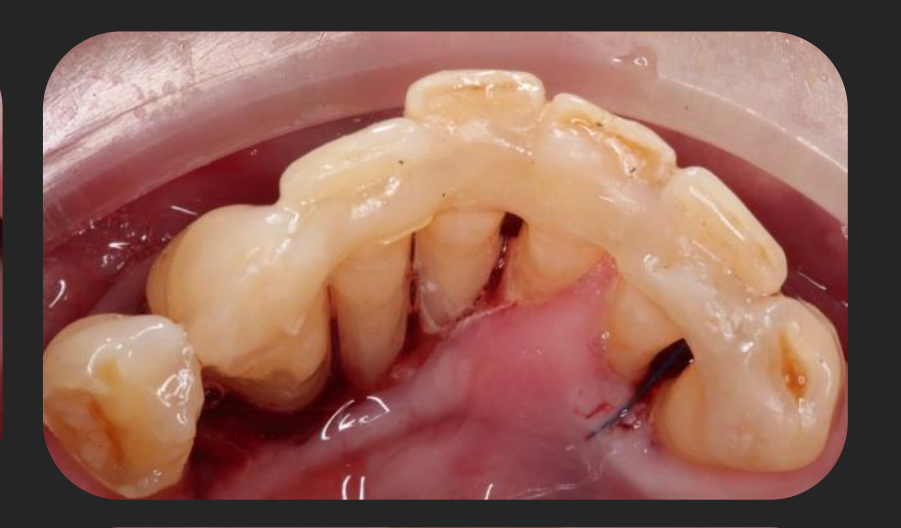
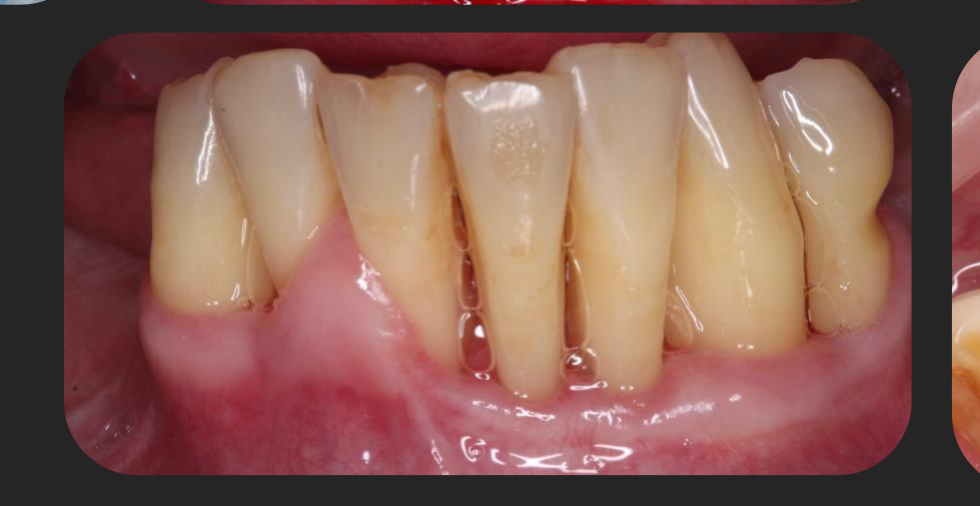
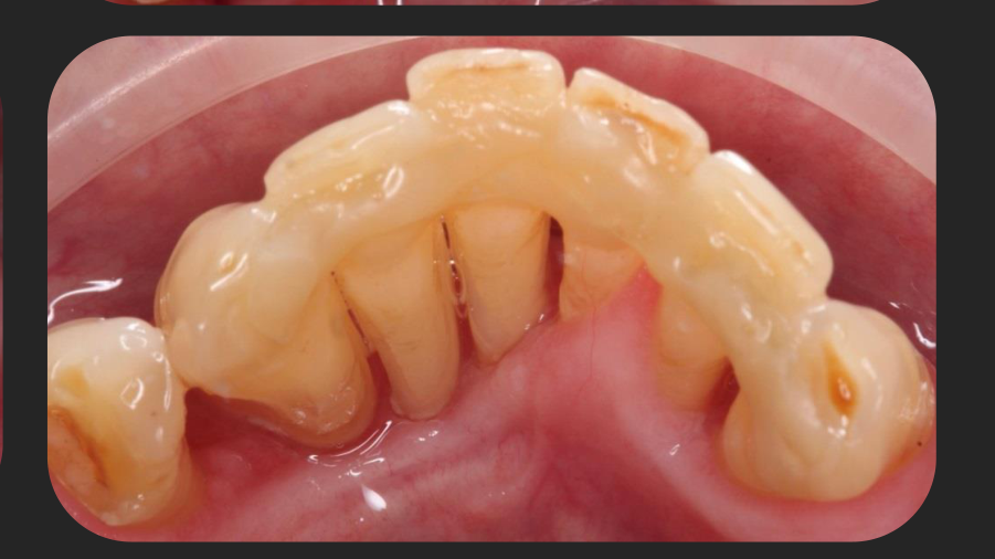
- Clinical photos showed exposed bone and missing gingiva.
Case Analysis and Final References4243
- Diagnosis: Localized Osteonecrosis.
- Cause: The patient had been over-applying “SM33” (an over-the-counter mouth ulcer medication) to the gingiva, causing tissue death and subsequent bone death.
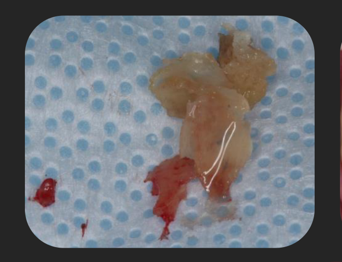
- The dead bone was eventually removed surgically.
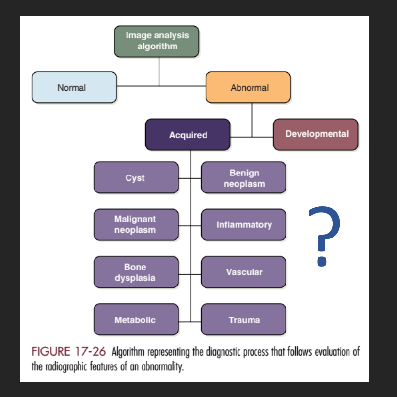
Table 1: Figure 17-26 Algorithm representing the diagnostic process that follows evaluation of the radiographic features of an abnormality.
- Normal
- Abnormal
- Acquired
- Cyst
- Benign neoplasm
- Malignant neoplasm
- Bone dysplasia
- Metabolic
- Developmental
- Inflammatory
- Vascular
- Trauma
- Acquired
Further Reading: http://dx.doi.org/10.1016/j.joms.2014.04.031
Courtesy of Dr. Thomas Briggs
 |  |  |
 |  |  |
 |  |  |
 |  |  |
Footnotes
-
Original PDF page 1: L7 Intraoral Radiographic Interpretation Part 2, p.1 ↩
-
Original PDF page 7: L7 Intraoral Radiographic Interpretation Part 2, p.7 ↩
-
Original PDF page 2: L7 Intraoral Radiographic Interpretation Part 2, p.2 ↩
-
Original PDF page 3: L7 Intraoral Radiographic Interpretation Part 2, p.3 ↩
-
Original PDF page 4: L7 Intraoral Radiographic Interpretation Part 2, p.4 ↩
-
Original PDF page 5: L7 Intraoral Radiographic Interpretation Part 2, p.5 ↩
-
Original PDF page 6: L7 Intraoral Radiographic Interpretation Part 2, p.6 ↩
-
Original PDF page 8: L7 Intraoral Radiographic Interpretation Part 2, p.8 ↩
-
Original PDF page 9: L7 Intraoral Radiographic Interpretation Part 2, p.9 ↩
-
Original PDF page 11: L7 Intraoral Radiographic Interpretation Part 2, p.11 ↩
-
Original PDF page 10: L7 Intraoral Radiographic Interpretation Part 2, p.10 ↩
-
Original PDF page 12: L7 Intraoral Radiographic Interpretation Part 2, p.12 ↩
-
Original PDF page 13: L7 Intraoral Radiographic Interpretation Part 2, p.13 ↩
-
Original PDF page 14: L7 Intraoral Radiographic Interpretation Part 2, p.14 ↩
-
Original PDF page 15: L7 Intraoral Radiographic Interpretation Part 2, p.15 ↩
-
Original PDF page 16: L7 Intraoral Radiographic Interpretation Part 2, p.16 ↩
-
Original PDF page 17: L7 Intraoral Radiographic Interpretation Part 2, p.17 ↩
-
Original PDF page 18: L7 Intraoral Radiographic Interpretation Part 2, p.18 ↩
-
Original PDF page 19: L7 Intraoral Radiographic Interpretation Part 2, p.19 ↩
-
Original PDF page 20: L7 Intraoral Radiographic Interpretation Part 2, p.20 ↩
-
Original PDF page 21: L7 Intraoral Radiographic Interpretation Part 2, p.21 ↩
-
Original PDF page 22: L7 Intraoral Radiographic Interpretation Part 2, p.22 ↩
-
Original PDF page 23: L7 Intraoral Radiographic Interpretation Part 2, p.23 ↩
-
Original PDF page 24: L7 Intraoral Radiographic Interpretation Part 2, p.24 ↩
-
Original PDF page 25: L7 Intraoral Radiographic Interpretation Part 2, p.25 ↩
-
Original PDF page 26: L7 Intraoral Radiographic Interpretation Part 2, p.26 ↩
-
Original PDF page 27: L7 Intraoral Radiographic Interpretation Part 2, p.27 ↩
-
Original PDF page 28: L7 Intraoral Radiographic Interpretation Part 2, p.28 ↩
-
Original PDF page 29: L7 Intraoral Radiographic Interpretation Part 2, p.29 ↩
-
Original PDF page 30: L7 Intraoral Radiographic Interpretation Part 2, p.30 ↩
-
Original PDF page 31: L7 Intraoral Radiographic Interpretation Part 2, p.31 ↩
-
Original PDF page 32: L7 Intraoral Radiographic Interpretation Part 2, p.32 ↩
-
Original PDF page 33: L7 Intraoral Radiographic Interpretation Part 2, p.33 ↩
-
Original PDF page 34: L7 Intraoral Radiographic Interpretation Part 2, p.34 ↩
-
Original PDF page 35: L7 Intraoral Radiographic Interpretation Part 2, p.35 ↩
-
Original PDF page 36: L7 Intraoral Radiographic Interpretation Part 2, p.36 ↩
-
Original PDF page 37: L7 Intraoral Radiographic Interpretation Part 2, p.37 ↩
-
Original PDF page 39: L7 Intraoral Radiographic Interpretation Part 2, p.39 ↩
-
Original PDF page 40: L7 Intraoral Radiographic Interpretation Part 2, p.40 ↩
-
Original PDF page 38: L7 Intraoral Radiographic Interpretation Part 2, p.38 ↩
-
Original PDF page 41: L7 Intraoral Radiographic Interpretation Part 2, p.41 ↩
-
Original PDF page 42: L7 Intraoral Radiographic Interpretation Part 2, p.42 ↩
-
Original PDF page 43: L7 Intraoral Radiographic Interpretation Part 2, p.43 ↩