Shining a Light on Anterior Aesthetics and Shade Selection
Front Matter and Copyright123
We are learning on Noongar land
The University of Western Australia
Material used in this recording may have been reproduced and communicated to you by or on behalf of The University of Western Australia in accordance with section 113P of the Copyright Act 1968.
Unless stated otherwise, all teaching and learning materials provided to you by the University are protected under the Copyright Act and is for your personal use only. This material must not be shared or distributed without the permission of the University and the copyright owner/s.
Black image with no visible text or content.
Case Study: Paediatric Bitewing Radiograph4
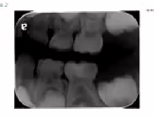
Case 2: Left bitewing, primary dentition. Teeth present: 26, 36, 63, 64, 65, 73, 74, 75. Findings on 8 teeth:

Maxillary Teeth5
- 26 — Unerupted
- 63 — Occlusal hard tissue missing into dentine
- 64 — Distal caries RA3 (EDJ / outer 1/3 dentine)
- 65 — Mesial caries RA1 (outer 1/2 enamel)
 |  |
Mandibular Teeth
- 36 — Unerupted
- 73 — Distal open contact (primate space)
- 74 — Distal caries RB4 (middle 1/3 dentine)
- 75 — Occlusal caries into middle 1/3 dentine
Patient age: 4–5 years
Presentation Title678910
Dr Amit Gurbuxani
MRACDS(DPH), MDPPH, BDS c, FADI, FICD, FPFA
Dr Amit Gurbuxani
MRACDS(DPH), MDPPH, BDSc, FADI, FICD, FPFA

Course Platform Screenshots111213
Main branch — “Main branch is protected. Protect this branch from force pushing or deletion, or require status checks before merging. [View documentation].”
- main
- 3 branches
- 1 tag

Code14
waterpolo14-star— “Mini redesign larger commits/adds/edits commit summary and metadata”- last commit: 10 hours ago
- Comments: 10
Files
/cli/deploy— “Minimal CLI deploy script” — last commit: last week/example images— “Lumen v1.0: offline dental clinical reference app in HTML & CSS” — last updated: 2 days ago/meta— “Auto-generated database write back to user — plus schema PCA” — yesterday/npm— “Mini npm registry larger commits/adds/edits commit summary and metadata” — 10 hours ago/design-input/design/random_layout— “Lumen v1.0: offline dental clinical reference app source code” — last week/prototype— “Lumen v1.0: offline dental clinical reference app source code” — last week/scripts— “JavaScript scripts for build process” — last week/polyglot.js— “Code.js: 3 tool wrapper — global namespace tag” — last weekSources-to-Add.md— “Lumen v1.0: offline dental clinical reference app source code” — last weeklumen-design-brief.md— “Lumen v1.0: offline dental clinical reference app source code” — last weeklumen-status.html— “Mini density larger commits/adds/edits commit summary and metadata” — 1 day ago
About
- Offline dental clinical guide
- lumen-v1.0: custom app
Activity
- ⭐ Star
- 👁 Watch
- 🚀 0 issues
- 🔒 0 issues
Releases
- 📦 1 tag
Deployments
- ✅ Production
- 🧪 Preview
- ➕ 28 deployments
Packages
- No packages found
- Fetch your first package
Contributors
- 1
Units — DENT5311_TS-B-3_2026 · Integrated Dental Practice 2
- Content
- Calendar
- Announcements
- Discussions
- Grade Centre
- Messages
- Groups
- Achievements
DENT5311 — Integrated Dental Practice 2
DENT5311_TS-B-3_2026 Integrated Dental Practice 2
Unit Content15
- ☐ C/O: Unit Outline
Getting Started
Start your learning journey with an overview of the unit here.
Academic, Wellbeing and Careers Support
Select this section to connect with support resources and services.
 |  |
Unit Contacts
Marina Osilarenvic Unit Co-ordinator
Details & Actions
- Attendance: [link]
- Books & Topics: [link]
Document showing “Lunon Build” in the top browser tab, 11:47 AM, 11/07/2024 on the taskbar
Request Timeout
This request takes too long to process, it is timed out by the server. If it should not be timed out, please contact administrator of this web site to increase Connection timeout.
Lecturer — Midline Decisions
A midline discrepancy does not automatically require treatment. If the remaining dental proportions are harmonious, correcting the midline may make treatment more invasive without producing a meaningful aesthetic improvement.
- The starting midline should be documented before treatment.
- The decision should consider facial structure, soft-tissue relationships, the maxillary and mandibular relationship, and the position most harmonious with the patient’s face.
Smile Analysis and Esthetic Design1617
Shining a Light on Anterior Aesthetics and Shade Selection. Dr Amit Gurbuxani. MRACDS(DPH), MDPPH, BDS, MSc, FADI, FICD, FPFA.
Dr Amit Gurbuxani
Components of Smile Analysis18192021
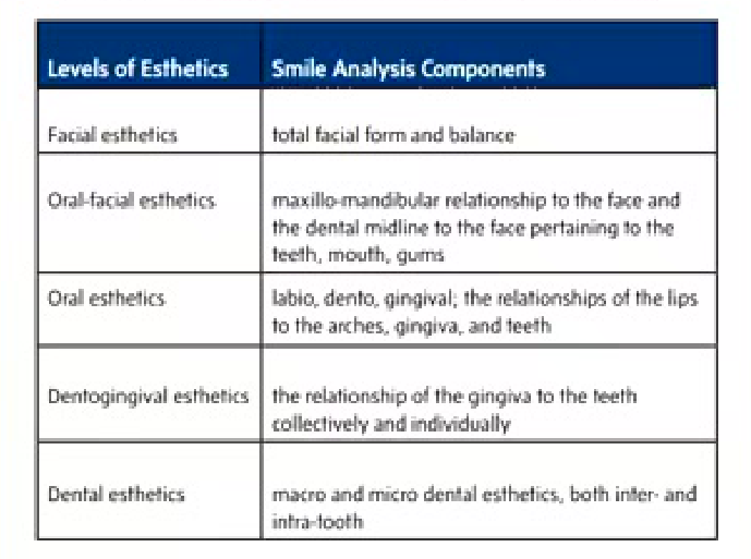
Table 1. Components of Smile Analysis and Esthetic Design.
| Levels of Esthetics | Smile Analysis Components |
|---|---|
| Facial esthetics | Total facial form and balance |
| Oral-facial esthetics | Maxillo-mandibular relationship to the face and the dental midline to the face pertaining to the teeth, mouth, gums |
| Oral esthetics | Labio, dento, gingival; the relationships of the lips to the arches, gingiva, and teeth |
| Dentogingival esthetics | The relationship of the gingiva to the teeth collectively and individually |
| Dental esthetics | Macro and micro dental esthetics, both inter- and intra-tooth |
Dental Press J Orthod May-Jun 2013;18(3):159-63. doi: 10.1590/S2176-94512013000300025.
Brachycephalic, dolichocephalic and mesocephalic: Is it appropriate to describe the face using skull patterns?
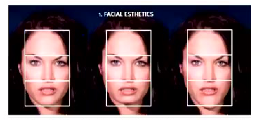
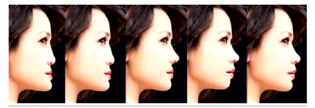
Figure 1: Three altered views of the same patient enable analysis of what can be accomplished to enhance facial and smile esthetics.
Figure: Side profile images of a woman’s face
Figure 2: Sagittal views best demonstrate which specialists should be involved in treatment, whether orthodontists or maxillofacial surgeons, to best esthetically alter the facial esthetics.
EA McIlwain, L Calp - J Cosmet Dent, 2013 – Volume 29
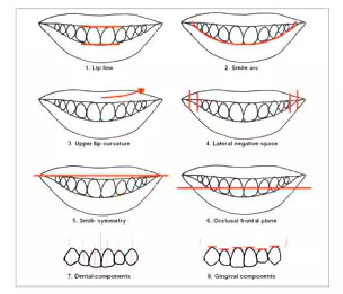
Dental diagram illustrating eight components of a balanced smile—including lip line, smile arc, upper lip curvature, lateral negative space, smile symmetry, occlusal frontal plane, dental components, and gingival components—drawn with red annotations on stylized mouths.
Overview: The Eight Components of a Balanced Smile
Roy Sabri, DDS, MS — Journal of Clinical Orthodontics

Midline2223242526
- Mid Line
Fixing the midline shift… Mission Impossible!
- Up to 4 mm midline shift barely anyone notices.
- Even though it’s one of the first things discussed in Smile evaluation.
Smile Analysis — EA McLaren, L. Culp - J Cosmet Dent, 2013 – Volume 29

Smile Curve2728293031
-
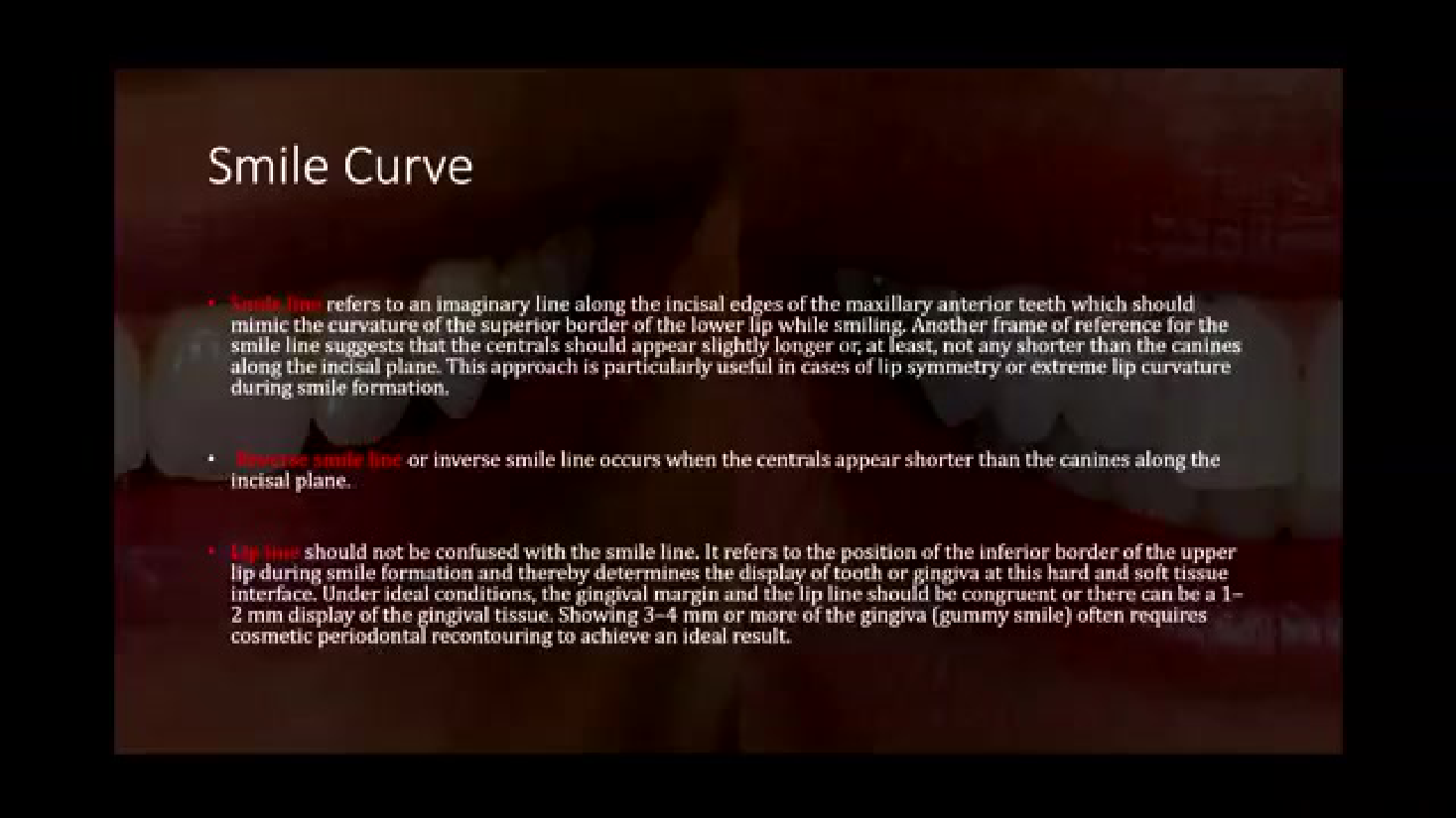
Smile line refers to an imaginary line along the incisal edges of the maxillary anterior teeth which should mimic the curvature of the superior border of the lower lip while smiling. Another frame of reference for the smile line suggests that the centrals should appear slightly longer or, at least, not any shorter than the canines along the incisal plane. This approach is particularly useful in cases of lip symmetry or extreme lip curvature during smile formation.
-
Reverse smile line or inverse smile line occurs when the centrals appear shorter than the canines along the incisal plane.
-
Lip line should not be confused with the smile line. It refers to the position of the inferior border of the upper lip during smile formation and thereby determines the display of tooth or gingiva at this hard and soft tissue interface. Under ideal conditions, the gingival margin and the lip line should be congruent or there can be a 1–2 mm display of the gingival tissue. Showing 3–4 mm or more of the gingiva (gummy smile) often requires cosmetic periodontal recontouring to achieve an ideal result.
Smile line refers to an imaginary line along the incisal edges of the maxillary anterior teeth which should mimic the curvature of the superior border of the lower lip while smiling. Another frame of reference for the smile line suggests that the centrals should appear slightly longer or, at least, not any shorter than the canines along the incisal plane. This approach is particularly useful in cases of lip symmetry or extreme lip curvature during smile formation.
-
Reverse smile line or inverse smile line occurs when the centrals appear shorter than the canines along the incisal plane.
-
Lip line should not be confused with the smile line. It refers to the position of the inferior border of the upper lip during smile formation and thereby determines the display of tooth or gingiva at this hard and soft tissue interface. Under ideal conditions, the gingival margin and the lip line should be congruent or there can be a 1–2 mm display of the gingival tissue. Showing 3–4 mm or more of the gingiva (gummy smile) often requires cosmetic periodontal recontouring to achieve an ideal result.
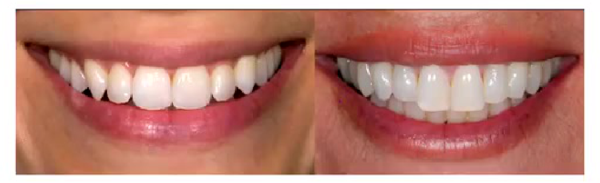 | 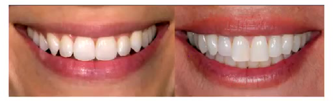 |
Interdental Proportion32333435363738394041
- Interdental proportion
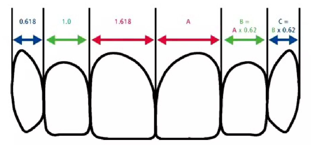
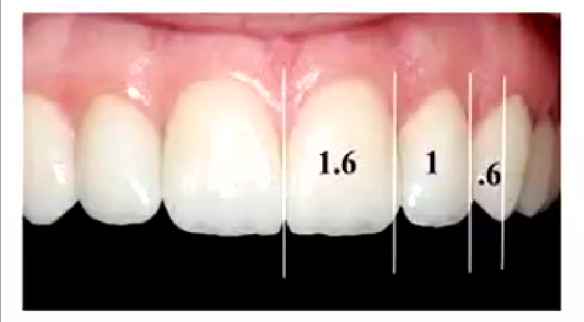
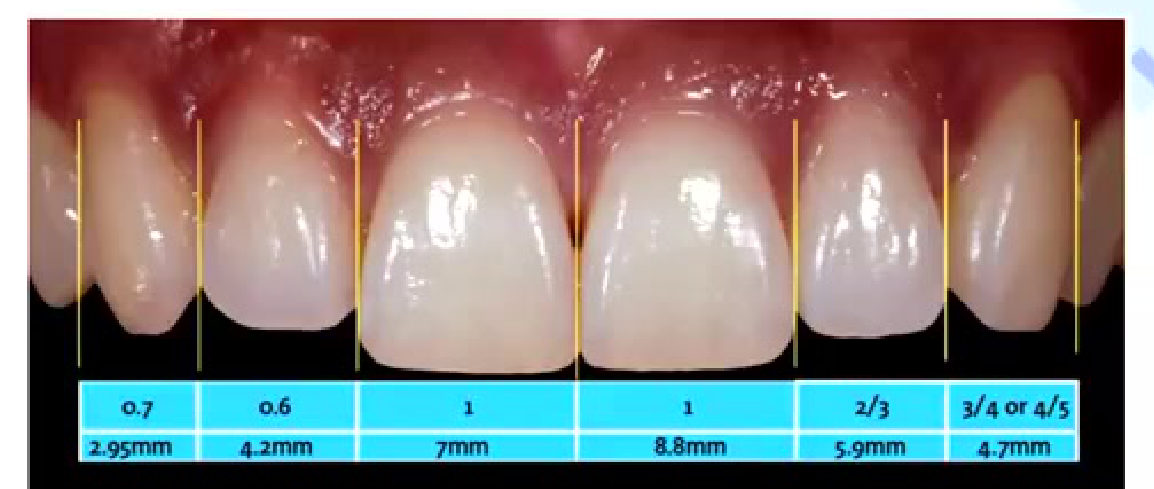
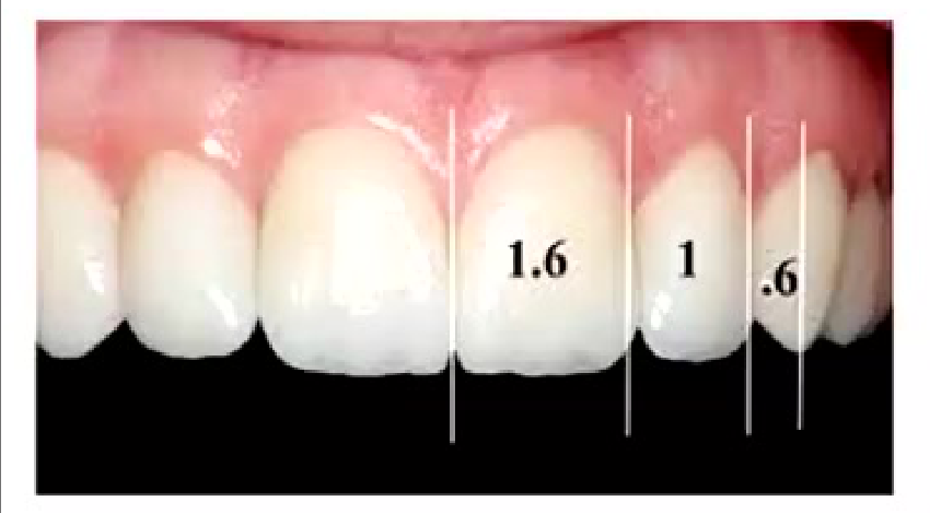
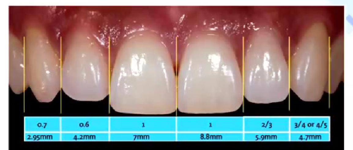
Width ratios across anterior teeth:
| 0.618 | 1.0 | 1.618 | A | B = A x 0.62 | C = B x 0.62 |
|---|
| 0.7 | 0.6 | 1 | 1 | 2/3 | 3/4 or 4/5 |
|---|---|---|---|---|---|
| 2.95mm | 4.2mm | 7mm | 8.8mm | 5.9mm | 4.7mm |
| 1.6 | 1 | .6 |
|---|
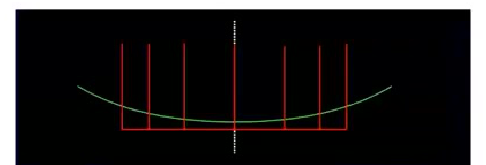
Dental Proportion and Central Incisor42434445
Correct dental proportion is related to facial morphology and is essential in creating an esthetically pleasing smile. Central dominance dictates that the centrals must be the dominant teeth in the smile and they must display pleasing proportions. They are the key to the smile.
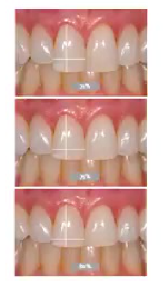
The proportions of the centrals must be esthetically and mathematically correct. The width-to-length ratio of the centrals should be approximately 4:5.
Lecturer — Central Incisor Matching
The central incisors are the most demanding anterior teeth to match because they sit next to each other and are directly visible to the patient. A small discrepancy in a lateral incisor may be less noticeable, but a mismatch between the central incisors can strongly affect the patient’s perception of the result.
- Before repairing a fractured central incisor, assess the contralateral tooth, whether it is a crown or veneer, the patient’s expectations, and their attention to detail.
- Giving the patient a mirror and observing how they identify the problem can reveal whether more detailed planning, a wax-up, and additional discussion are needed.
Principles of smile design — Mohan Bhavanth (Compendium Dent, 2010 Oct-Dec, 13(4): 225-232)
Acceptable width-to-length ratio falls between 70–85%.
Depending on facial form: long and dolichocephalic or square/brachycephalic.
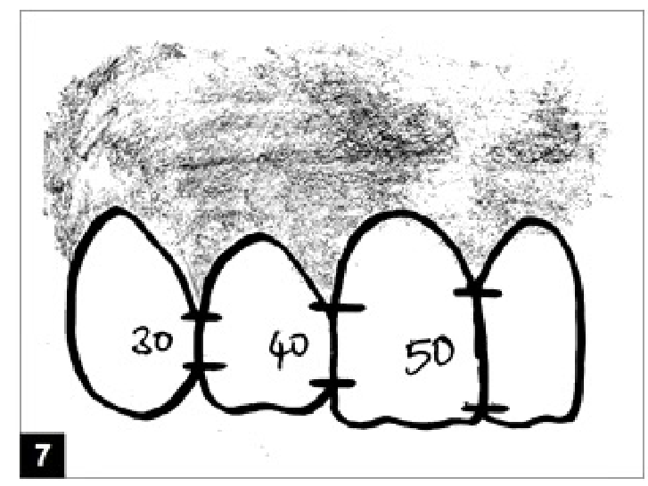
Interdental contact area and point
Interproximal contact area (ICA):
- It is defined as the broad zone in which two adjacent teeth touch.
- It follows the 50:40:30 rule in reference to the maxillary central incisor.
 |  |
Gingival Symmetry464748
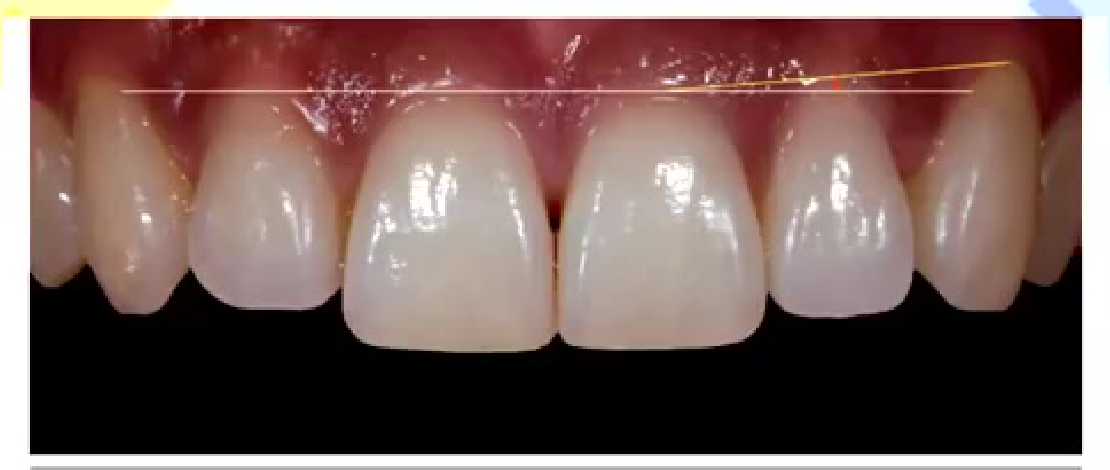
Figure 6: Gingival symmetry in relation to the centrals, laterals, and canines is essential to esthetics. Optimal esthetics is achieved when the gingival line is relatively horizontal and symmetrical on both sides of the midline, when considering the centrals and
Smith Analysis — EA McLaren, L Cupp - J Cosmet Dent 2013 – Volume 29
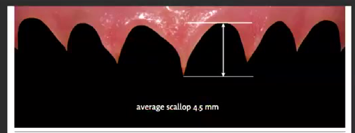
- Gingival Zenith
- Embrasure space
- Papillae Curve
The papillae curve should be between 4–5 mm.
 |  |
Labiolingual Inclination495051
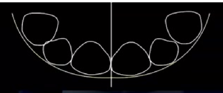
- Twelve o’clock analysis
The guide for labiolingual inclination is as follows:
- Maxillary central incisor – positioned vertically or slightly labial
- Maxillary lateral incisor – cervical is tucked in, incisal edge inclined slightly labially
- Maxillary canine – cervical area positioned labially, cusp tip lingually angulated
Lecturer — Twelve O’Clock View
A frontal view may appear satisfactory while a tooth is excessively bulky or incorrectly inclined from the incisal direction. During composite finishing, establish occlusion and approximate proportions first, then adjust length, assess the 12 o’clock view, and refine the marginal ridges and surface anatomy before the final finishing stage.
Angle Orthod. 2011 Jan; 81(1):121–129 doi: 10.1348/000398809x488466 — Effect of maxillary incisor labiolingual inclination and anteroposterior position on smiling profile esthetics. Le Cochec et al.
Incisal Display and Phonetics5253545556
Separate chapter all together.
4 mm of incisal display at rest
- 2 mm of gingival display
- 2 mm distance from the incisal edge to lower lip line
Variables and factors that may affect smile design: A mini review — Tan Ming Hoe, Jennifer Ting, Lu Siew Chul, Tan Mei Wen, Muhammed Jasim — International Journal of Contemporary Dental and Medical Reviews (2015)
-
M sound: After pronunciation, the lips return to their normal rest position, allowing evaluation of the amount of the tooth display in rest position.
-
E sound: The maxillary incisal edge position should be positioned halfway between the upper and lower lip during the “E” sound.
-
F and V sounds: Fricative sounds are produced by the interaction of the maxillary incisal edge with the inner edge of the lower lips’ vermilion border. Thus, fricative sounds help to determine the labiolingual position and length of the maxillary teeth.
-
S sound: During pronunciation, the mandibular central incisors are positioned 1 mm behind and 1 mm below the maxillary incisal edge.
-
The position of the upper incisal edges should be at the inner vermilion border of the lower lip or usually referred to as the wet-dry line. This is one of the most reliable guidelines used to determine the incisal edge length.
-
The importance of the smile line now becomes apparent with the understanding that control of escaping air between the upper incisal edges and the lower lip is necessary for proper phonetics. If the upper incisal edges are not correctly determined they will not relate to the lip correctly and a strained lip position will be required for making F and V sounds.
-
Because of variations of lower tooth position, the S sound is not the best determinant, but it serves as an excellent verification method. Since air can be restricted for the S sound between the lower incisal edges and either lingual surfaces or incisal edges of the uppers, an error on any part of the upper contour might affect the S sound. Too much space will cause a lisp. Too little space causes the teeth to bump.
-
If the contour of the upper cingulum is too bulky, the tongue may bump into it when making T and D sounds.
Lecturer — Phonetic Testing
Prepared sentences containing M, F, V and S sounds are more useful than asking patients to repeat isolated sounds. Recording the patient while reading may help communicate with the laboratory and reveal whether the teeth are too far forward or backward.
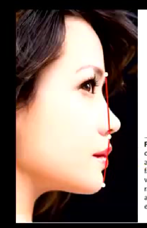
Figure 3: Drawing a line on the glabella, subnasale, and pogonion enables a fast evaluation of esthetics without the need for radiographs to determine alignment of ideal facial elements.
Smile Analysis — EA McLaren, L Culp - J Cosmet Dent, 2013 - Volume 29
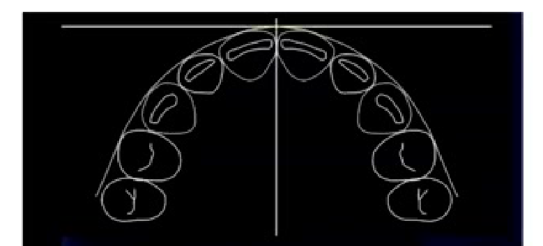 | 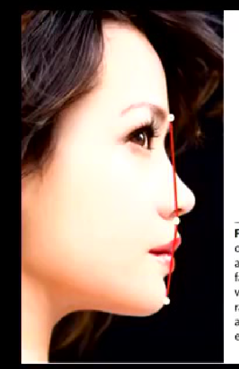 |
Case Application Review575859
Post Ortho (2014)
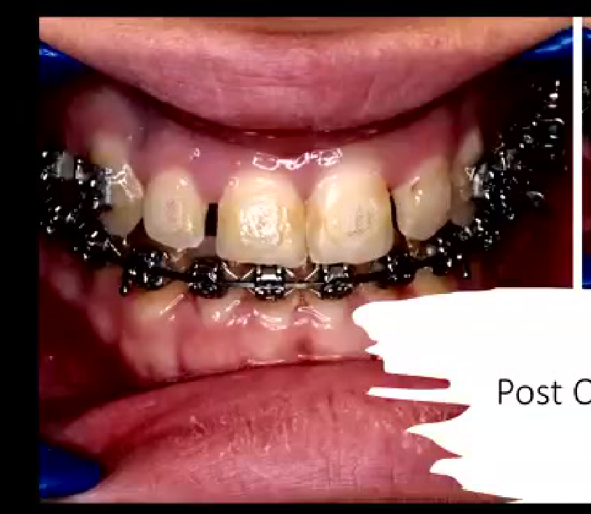 | 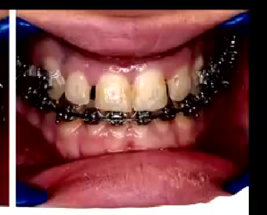 |
Smile Design Principles Revisited6061626364656667686970717273747576777879
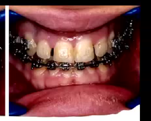
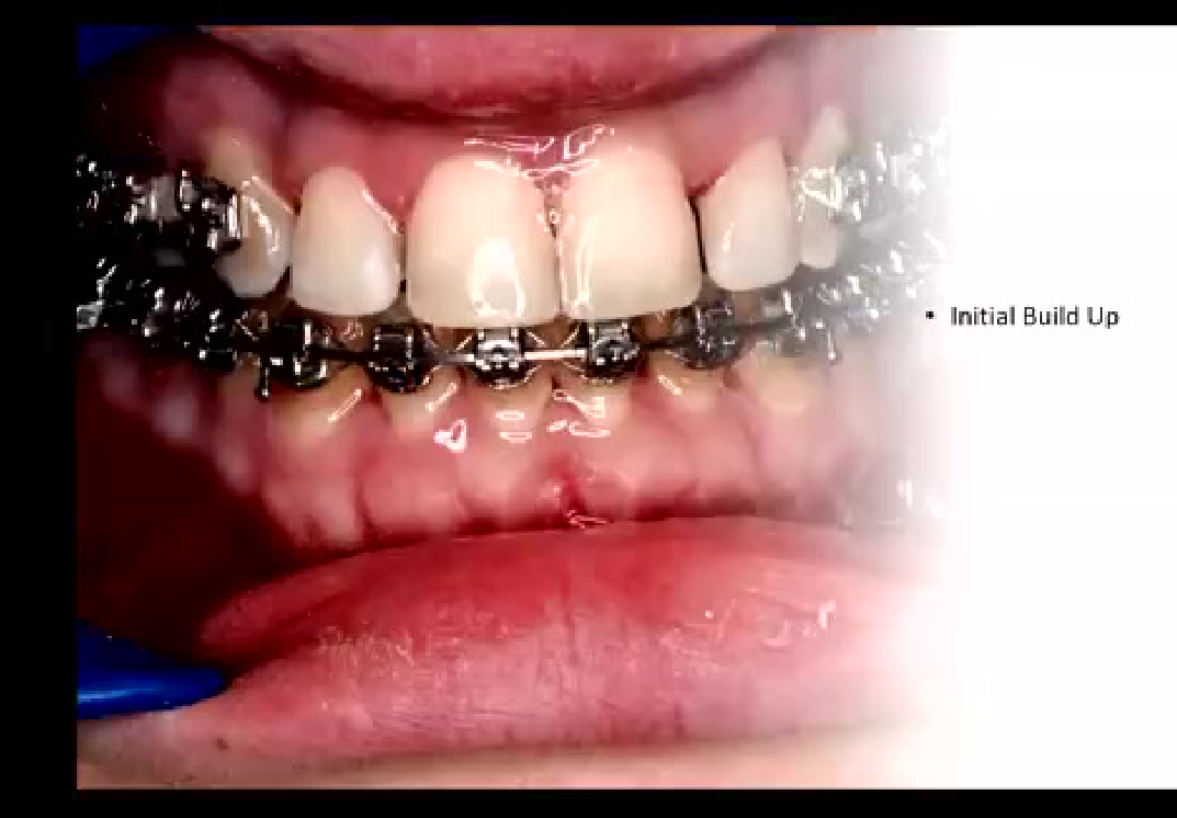
Orthodontic Space Closure and Build-Ups
An orthodontist referred a patient for restoration of the lateral incisors after orthodontic treatment. A laboratory wax-up was used to design the teeth according to the golden-proportion guide while leaving spaces for the orthodontist to close; after the build-ups, the patient returned for final space closure.
- The lecturer assessed the deep bite and other factors, and could use a digital scanner and digital wax-up instead of traditional impressions.
- Gingival zeniths, papillae and proportions were checked before the build-ups.
- A black triangle later remained because the interdental papilla and bone did not fill the space.
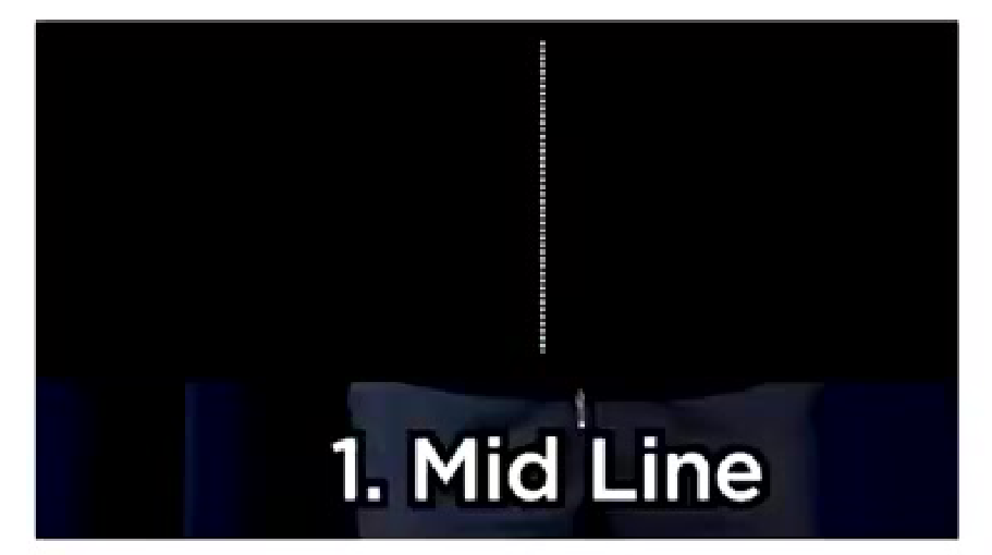
- Mid Line
Fixing the midline shift… Mission Impossible!
- Up to 4 mm midline shift barely anyone notices.
- Even though it’s one of the first things discussed in Smile evaluation.
Smile Analysis — EA McLaren, L. Culp - J Cosmet Dent, 2013 - Volume 29
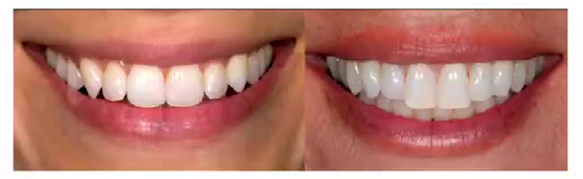
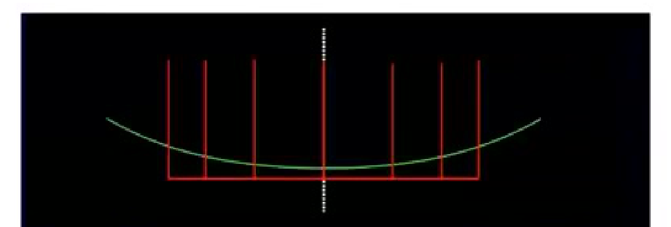
- Smile Curve
-
Smile line refers to an imaginary line along the incisal edges of the maxillary anterior teeth which should mimic the curvature of the superior border of the lower lip while smiling. Another frame of reference for the smile line suggests that the centrals should appear slightly longer or, at least, not any shorter than the canines along the incisal plane. This approach is particularly useful in cases of lip symmetry or extreme lip curvature during smile formation.
-
Reverse smile line or inverse smile line occurs when the centrals appear shorter than the canines along the incisal plane.
-
Lip line should not be confused with the smile line. It refers to the position of the inferior border of the upper lip during smile formation and thereby determines the display of tooth or gingiva at this hard and soft tissue interface. Under ideal conditions, the gingival margin and the lip line should be congruent or there can be a 1–2 mm display of the gingival tissue. Showing 3–4 mm or more of the gingiva (gummy smile) often requires cosmetic periodontal recontouring to achieve an ideal result.
Lecturer — Age and Display
The amount of upper and lower tooth display contributes to the appearance of age. As lip musculature weakens with age, less upper tooth and more lower tooth may be displayed; drooping lips, worn dentition and dentures may contribute to an older appearance.
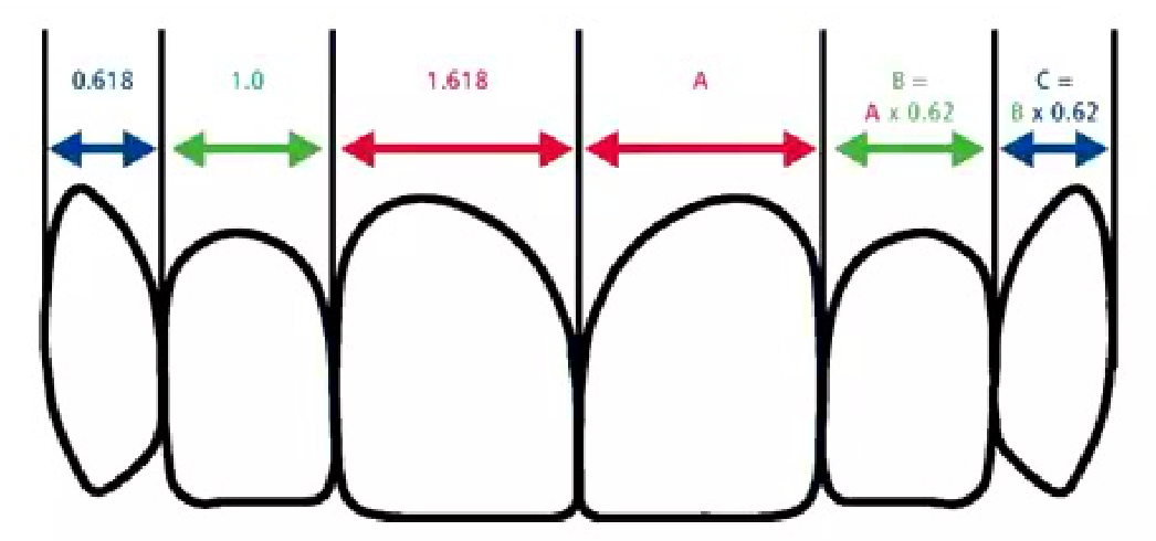
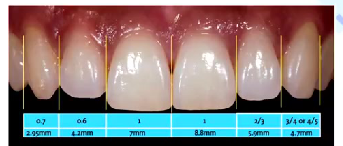
Golden proportion (Lombardi): When viewed from the facial, the width of each anterior tooth is 60% of the width of the adjacent tooth (mathematical ratio being 1.6:1:0.6).
| 0.618 | 1.0 | 1.618 | A | B = A x 0.62 | C = B x 0.62 |
|---|---|---|---|---|---|
| (blue double arrow) | (green double arrow) | (red double arrow) | (red double arrow) | (green double arrow) | (blue double arrow) |
| 0.7 | 0.6 | 1 | 1 | 2/3 | 3/4 or 4/5 |
|---|---|---|---|---|---|
| 2.95mm | 4.2mm | 7mm | 8.8mm | 5.9mm | 4.7mm |
- Central incisor proportion
Acceptable width-to-length ratio falls between 70–85%.
Depending on facial form: long and dolichocephalic or square/brachycephalic.
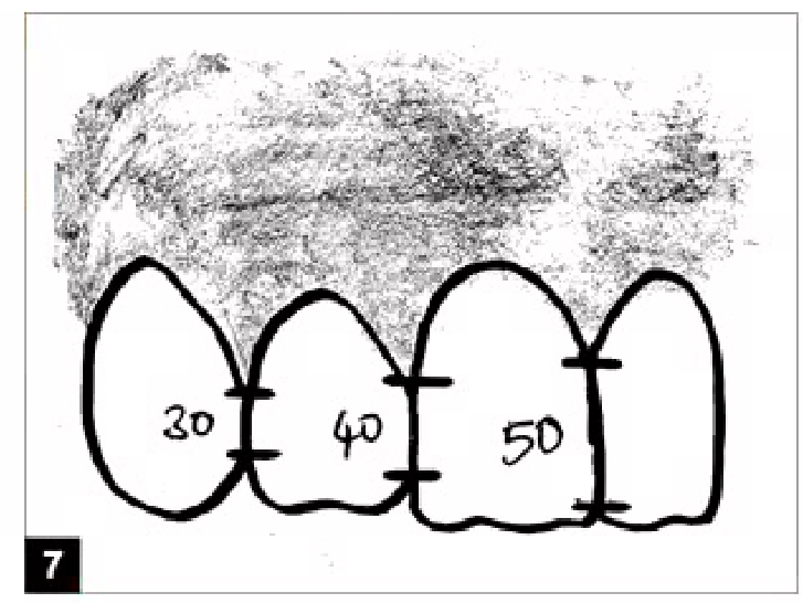
Interdental contact area and point
Interproximal contact area (ICA):
-
It is defined as the broad zone in which two adjacent teeth touch.
-
It follows the 50:40:30 rule in reference to the maxillary central incisor.
-
Gingival curve
- Gingival Zenith
- Embrasure space
- Papillae Curve
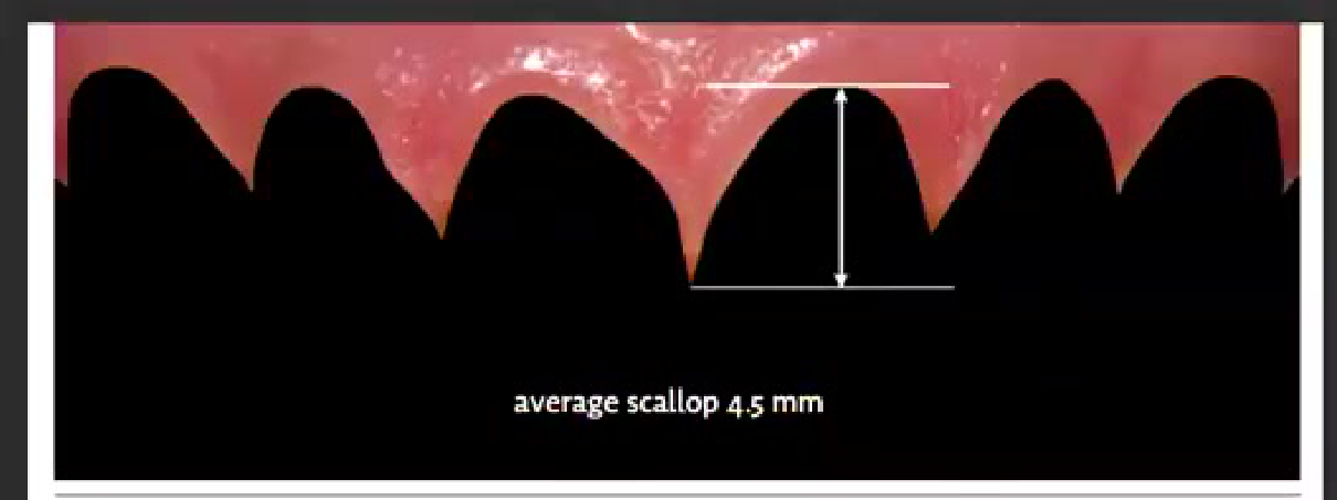
Average scallop: 4.5 mm
The papillae curve should be between 4–5 mm.
Lecturer — Periodontal Stability
Recession can make ideal gingival symmetry impossible, and restorative treatment alone may make teeth appear too long or disproportionate in a patient with recession and a gummy smile.
- Periodontal assessment may include evaluation of stability, grafting or tunnel grafting, recession classification and periodontal clearance before extensive composite or ceramic treatment.
- Future recession can expose restorative margins and compromise the appearance of the result.
Separate chapter all together.
The Rule of 42.2
- 1 mm display at rest
- Minus 3 mm gingival display
- 4 mm display edge to lower lip
4 mm of incisal display at rest
- 2 mm of gingival display
- 2 mm distance from the incisal edge to lower lip line
Variables and factors that may affect smile design: A mini review — Tan Ming Hoe, Jennifer Ting, Lu Siew Chui, Tan Mei Wen, Mohammed Jasim Al-Juboori — International Journal of Contemporary Dental and Medical Reviews (2015)

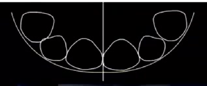
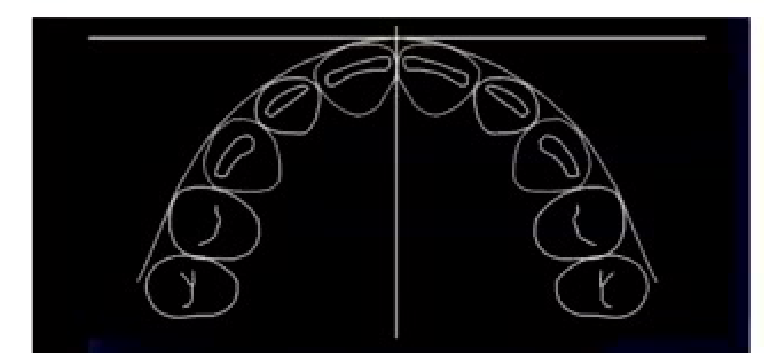
Phonetics and Clinical Implications80818283
- Buccal of the central from the profile view
-
M sound: After pronunciation, the lips return to their normal rest position, allowing evaluation of the amount of the tooth display in rest position.
-
E sound: The maxillary incisal edge position should be positioned halfway between the upper and lower lip during the “E” sound.
-
F and V sounds: Fricative sounds are produced by the interaction of the maxillary incisal edge with the inner edge of the lower lips’ vermilion border. Thus, fricative sounds help to determine the labiolingual position and length of the maxillary teeth.
-
S sound: During pronunciation, the mandibular central incisors are positioned 1 mm behind and 1 mm below the maxillary incisal edge.
-
The position of the upper incisal edges should be at the inner vermilion border of the lower lip or usually referred to as the wet-dry line. This is one of the most reliable guidelines used to determine the incisal edge length.
-
The importance of the smile line now becomes apparent with the understanding that control of escaping air between the upper incisal edges and the lower lip is necessary for proper phonetics. If the upper incisal edges are not correctly determined they will not relate to the lip correctly and a strained lip position will be required for making F and V sounds.
-
Because of variations of lower tooth position, the S sound is not the best determinant, but it serves as an excellent verification method. Since air can be restricted for the S sound between the lower incisal edges and either lingual surfaces or incisal edges of the uppers, an error on any part of the upper contour might affect the S sound. Too much space will cause a lisp. Too little space causes the teeth to bump.
-
If the contour of the upper cingulum is too bulky, the tongue may bump into it when making T and D sounds.
Smile Analysis — EA McLaren, L Culp - J Cosmet Dent, 2013 – Volume 29
Ten Steps of the Smile Frame848586878889
10 steps of the Smile Frame
- Initial Build Up
These principles are used as a guide rather than a rigid mathematical formula. Most authors recommend creating harmony and balance by eye via proper adjustment and evaluation rather than any formula.
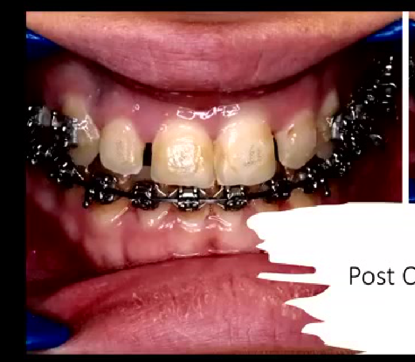
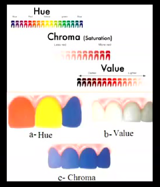
Shade Selection: Hue, Value and Chroma9091
What is hue, value and chroma?
Lecturer — Cured Shade Samples
When uncertain between similar composite shades, place small samples on the etched tooth, cure them, and compare them with the surrounding tooth. The shade that visually disappears or blends most closely is the better match, whereas the shade that stands out is less suitable.
Clinical Cases
Case: Facial Form Assessment
Question
Scenario: A gentleman in the audience is asked to turn around so the class can assess his facial form.
What’s shown: The physical appearance of the gentleman’s face and jaw structure.
Consider: How to classify his facial form (brachycephalic, dolichocephalic, or mesocephalic) based on his jaw and face shape.
Answer
Observations:
- The gentleman has a wide, square jaw.
Reasoning: Brachycephalic faces are generally associated with a Class 3 wide jaw and a more square shape, whereas dolichocephalic faces are more narrow, round, oval, or longish, and mesocephalic is somewhere in between.
Takeaway: Facial form can be quickly assessed in a clinical setting by observing the jaw width and face shape to classify the patient as brachycephalic, dolichocephalic, or mesocephalic.
Case: Midline Shift Evaluation
Question
Scenario: A classic photograph of an individual with a significant midline shift is presented to demonstrate midline disparity.
What’s shown: An image of a person’s smile and face showing a noticeable shift between the upper and lower dental midlines.
Consider: Whether to shift the upper or lower midline during cosmetic treatment and what factors influence this decision.

Answer
Observations:
- There is a visible midline shift or disparity between the upper and lower arches.
- The shift is up to 4 millimeters, which is often barely noticeable to the untrained eye.
Reasoning: The decision to move a midline depends on the facial structure, soft tissue relationship, and skeletal relationship. Moving a midline is difficult and may require orthodontics or orthognathic surgery, so a midline shift is often acceptable if proportions are correct.
Takeaway: A midline shift of up to 4 millimeters is often acceptable and should not automatically dictate treatment; the decision to correct it depends on overall facial and soft tissue proportions.
Case: Smile Curve Comparison
Question
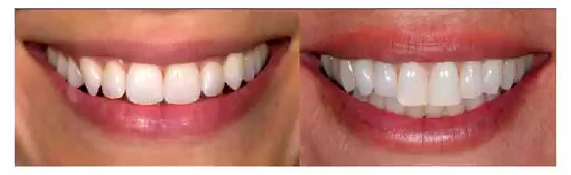
Scenario: Two images of smile curves (left and right) are shown to the class to evaluate aesthetic preference.
What’s shown: Two different smile curves, one of which is preferred by the majority of the class.
Consider: Why one smile curve is perceived as more pleasing and youthful compared to the other.
Answer
Observations:
- The preferred smile shows a more proportionate curve and greater display of upper teeth.
- The less preferred smile shows less upper tooth display.
Reasoning: As people age, the levator labii superioris muscle weakens, leading to less upper tooth display and more lower tooth display, which gives an “older” appearance. An ideal smile shows about 3/4 upper and less than 1/4 lower tooth display.
Takeaway: A pleasing, youthful smile curve mimics the curvature of the lower lip and displays more upper teeth, whereas reduced upper tooth display is associated with aging.
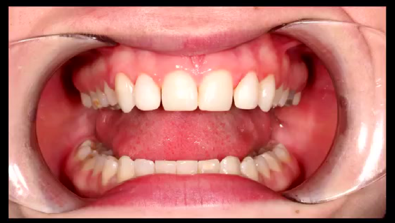
Case: Reverse Smile Line in Erosive Wear
Question
Scenario: An example of a reverse (or inverse) smile line is presented.
What’s shown: An image where the central incisors appear shorter than the canines along the incisal plane.
Consider: What clinical condition causes this specific incisal wear pattern.
Answer
Observations:
- The central incisors are worn down significantly.
- The incisal edges of the centrals are shorter than the canines.
Reasoning: This reverse smile line occurs in erosive cases where the central teeth have been worn away badly, altering the natural incisal plane where centrals should ideally be slightly longer than or equal to the canines.
Takeaway: A reverse smile line, where centrals appear shorter than canines, is a key indicator of severe erosive tooth wear.
Case: Orthodontic Case with Deep Bite
Question
Scenario: A patient with a deep bite is referred by an orthodontist for composite build-ups on the lateral incisors.
What’s shown: A digital wax-up and clinical scenario where the laterals are built up to the golden proportion, leaving spaces for the orthodontist to close.
Consider: How to manage the remaining spaces and maintain ideal proportions when combining restorative and orthodontic treatment.
Answer
Observations:
- The lateral incisors are built up following the 1:1.6:0.6 golden proportion rule.
- Spaces are intentionally left adjacent to the build-ups.
Reasoning: If the restorative dentist closes the spaces, the proportions of the teeth will be lost, making the laterals or centrals look disproportionately large. The orthodontist must close the remaining spaces to achieve the final ideal proportion.
Takeaway: When combining restorative build-ups with orthodontics, build the teeth to ideal proportions and leave spaces for the orthodontist to close, preventing the final restorations from looking disproportionately wide.
Case: The “Mirror Test” for a Chipped Central Incisor
Question
Scenario: A patient presents with a fractured central incisor and an existing crown or veneer on the other central.
What’s shown: A clinical scenario where the dentist uses a mirror to gauge the patient’s aesthetic expectations and perfectionism.
Consider: How to assess the patient’s psychological approach to aesthetics and adjust treatment planning and pricing accordingly.
Answer
Observations:
- The patient is handed a mirror to identify what is wrong with their smile.
- The distance at which the patient holds the mirror and their level of scrutiny vary.
Reasoning: If the patient holds the mirror close and scrutinizes minor details, they are highly particular and will require extensive planning, wax-ups, and higher fees. If they hold it further away and only notice the obvious chip, they are less particular and can be treated quickly in a standard appointment.
Takeaway: Evaluating how a patient examines their smile with a mirror helps gauge their perfectionism, allowing the dentist to tailor the treatment plan, time, and pricing to their psychological expectations.
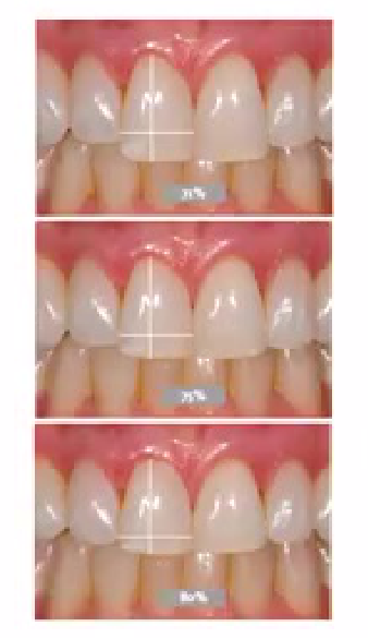
Case: Central Incisor Width-to-Length Ratio Selection
Question
Scenario: Three different images of central incisors with varying width-to-length ratios (top, middle, bottom) are shown to the class.
What’s shown: Three options for central incisor proportions, with the top one having a 71% height-to-width ratio, and varying lateral incisor lengths.
Consider: Which proportion the class prefers and why the top option is rejected despite having an acceptable ratio.
Answer
Observations:
- The class prefers the middle or bottom options.
- The top option is rejected by everyone.
Reasoning: The rejection of the top option is not due to the central incisor’s 71% ratio, but because the lateral incisors in that image are much shorter. The eye is drawn to the overall proportion and length of the adjacent teeth, not just the isolated central incisor ratio.
Takeaway: Aesthetic perception of a single tooth’s proportion is heavily influenced by the length and proportions of the adjacent teeth; harmony in the entire segment is more important than isolated mathematical ratios.
Case: Managing Black Triangles in Diastema Closure
Question
Scenario: A patient with gingival recession and a diastema undergoes composite build-up to close the space.
What’s shown: An image of a black triangle between the central incisors after space closure, and a proposed solution using a longer contact point.
Consider: Why the black triangle forms and how to aesthetically manage it when bone support is lacking.
Answer
Observations:
- A black triangle is visible between the centrals due to missing papilla.
- The contact point is extended apically using ceramic or composite.
Reasoning: According to Tarnow’s rule, if the distance from the bone crest to the contact point is greater than 5mm, the papilla will not fill the space. By artificially extending the contact point apically with the restoration, the visual black triangle is closed, even though the actual gingival margin hasn’t moved.
Takeaway: When closing diastemas in patients with gingival recession, extending the restorative contact point apically can hide black triangles by compensating for the lack of interdental papilla.
Case: Recession and Gummy Smile Referral
Question
Scenario: A patient presents with significant gingival recession and a gummy smile, requesting aesthetic improvement.
What’s shown: A clinical scenario where restorative treatment alone would compromise aesthetics.
Consider: The appropriate interdisciplinary management for a patient with unstable gingival margins and excessive gingival display.
Answer
Observations:
- The patient has recession defects and a gummy smile.
- Restorative lengthening would make the teeth look disproportionate.
Reasoning: Attempting to restore these teeth without addressing the gingival levels will result in disproportionate tooth lengths and poor aesthetics. The patient must be referred to a periodontist for gingival grafts or crown lengthening to stabilize the margins and correct the gummy smile before restorative work.
Takeaway: Patients with significant recession and a gummy smile require periodontal evaluation and soft tissue management prior to restorative treatment to ensure stable and proportionate aesthetic outcomes.
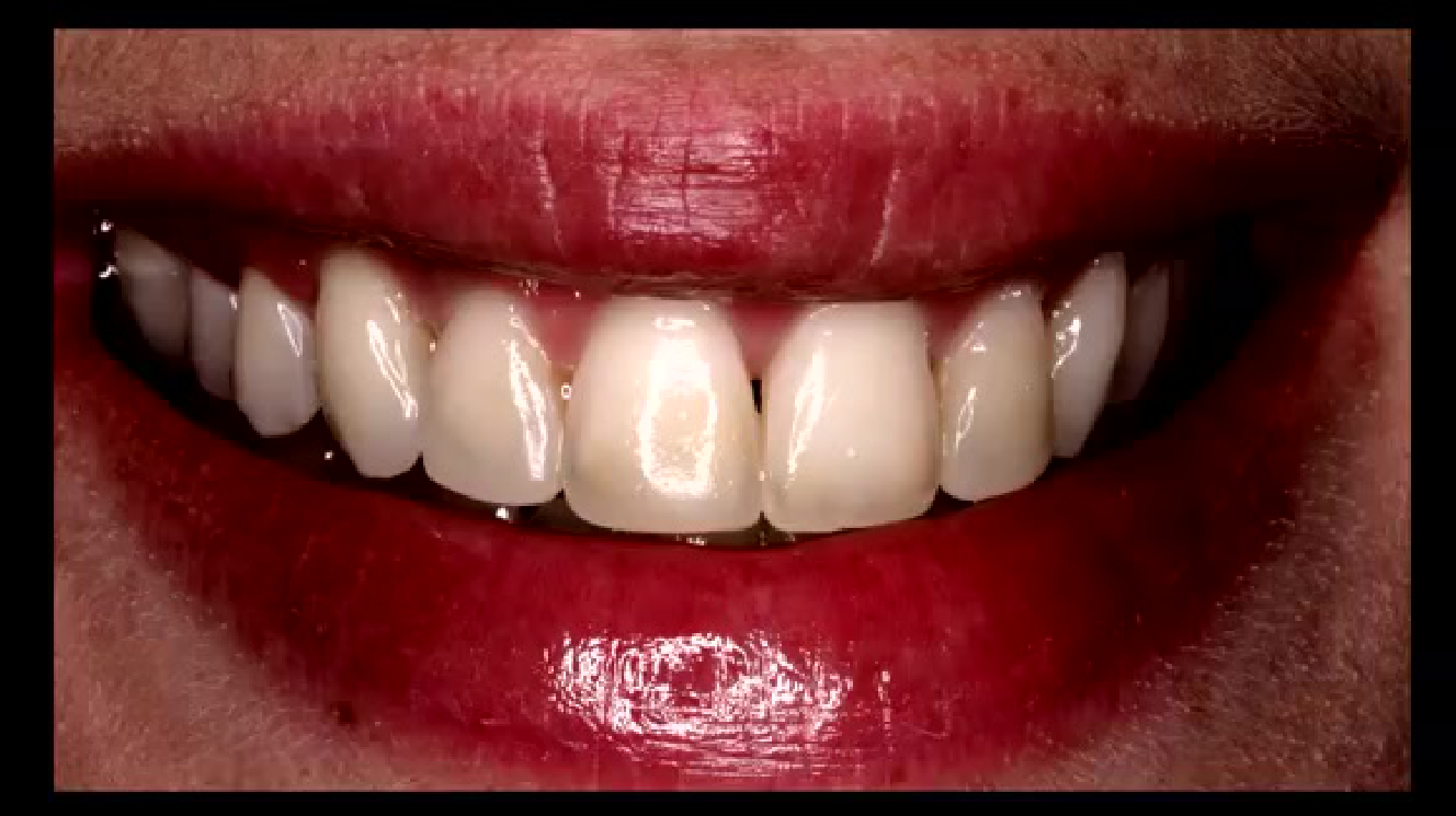
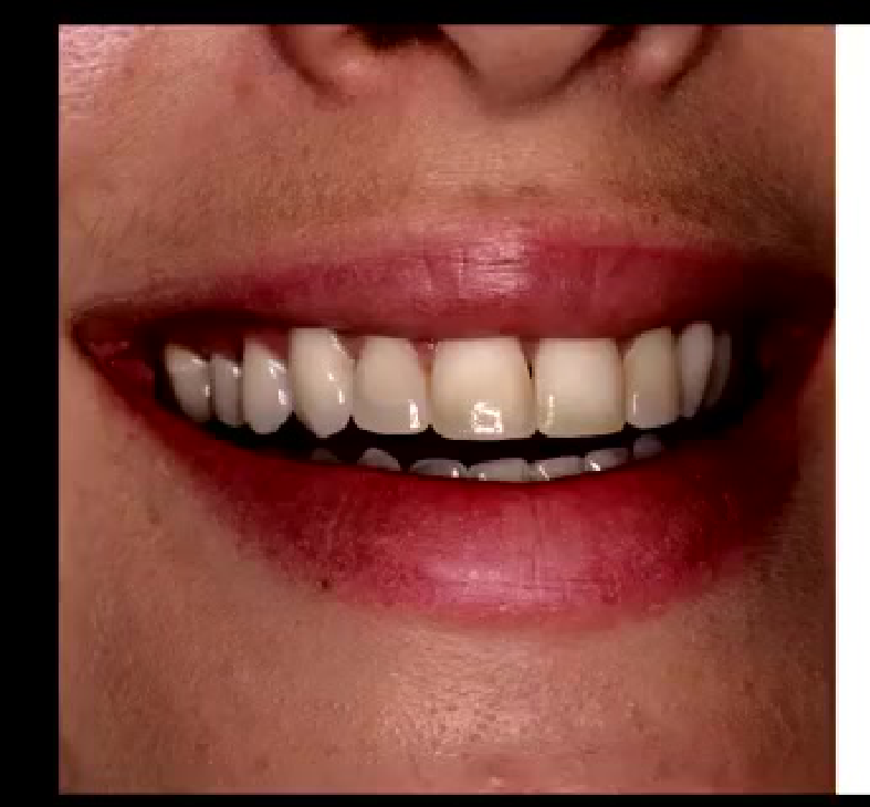
Case: Long-Term Follow-Up of Post-Ortho Composite Build-ups
Question
Scenario: A post-orthodontic case featuring composite build-ups with tints and colors is reviewed.
What’s shown: Clinical images of the case immediately after treatment and at a nine-year follow-up.
Consider: The long-term durability and aesthetic changes of multi-layered composite build-ups over time.
Answer
Observations:
- At nine years, the composite shows some wear and yellowing.
- The tints and colors are still visible and the build-ups remain functional.
Reasoning: While composites can show some surface wear and color changes over nearly a decade, well-executed multi-layered composites with tints can last many years, proving that composites can be a durable long-term option when placed correctly.
Takeaway: High-quality, multi-layered composite build-ups can remain functional and aesthetically acceptable for up to nine years, demonstrating the long-term viability of composite resin in anterior aesthetics.
Case: Polarized Filter for Enamel Hypoplasia
Question
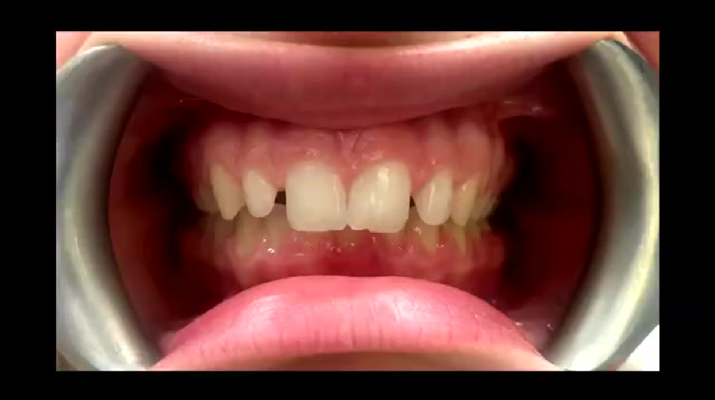
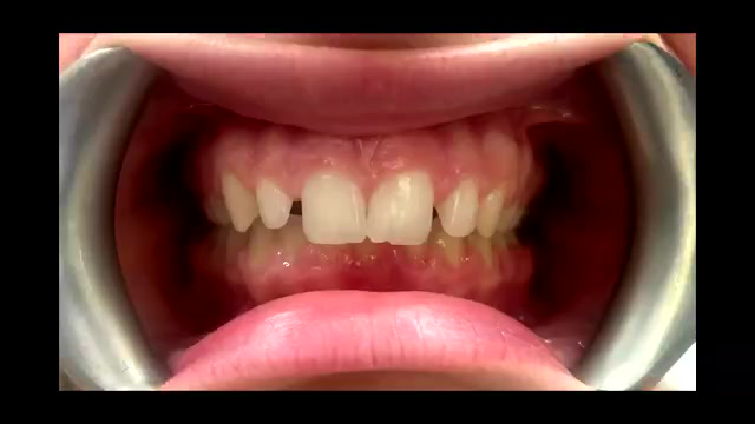
Scenario: A patient presents with a fractured central incisor and visible white patches.
What’s shown: An image taken with a polarized filter that reveals the depth and extent of the white patches.
Consider: How to accurately assess the depth of white spot lesions or hypoplasia before attempting a composite repair.
Answer
Observations:
- The polarized filter removes surface glare.
- The white patches are revealed to be deeper than they appear to the naked eye.
Reasoning: Surface glare can mask the true depth of enamel defects. Using a polarized filter allows the clinician to see through the surface and assess the actual depth of the hypoplasia, which is critical for planning the layering and opacity of the composite repair.
Takeaway: A polarized filter is a valuable diagnostic tool for assessing the true depth of enamel white patches or hypoplasia by eliminating surface glare, aiding in accurate composite shade and opacity selection.
Case: Lack of Opalescence in a Composite Lateral Incisor
Question
Scenario: A patient receives a composite build-up on a fractured lateral incisor using a new composite brand.
What’s shown: A clinical scenario where the restoration looks acceptable in the clinic but fails under specific lighting conditions.
Consider: Why the patient was unhappy with the restoration in a specific environment and how to prevent it.
Answer
Observations:
- The patient visited a disco/nightclub and the tooth appeared dark or invisible.
- The composite used lacked opalescence.
Reasoning: Natural enamel exhibits opalescence, reflecting blue light and transmitting orange light. A composite lacking this property will absorb light and appear dark under UV or disco lighting. Checking the composite’s opalescent properties before use is essential for patients who frequent such environments.
Takeaway: Always verify the opalescent properties of a composite material, as a lack of opalescence can cause the restoration to appear unnaturally dark under specific lighting conditions like nightclub UV lights.
Case: Opalescence Mismatch Between Ceramic Veneers and Composite
Question
Scenario: A patient receives ceramic veneers on the central incisors and a composite build-up on the lateral incisor.
What’s shown: A clinical scenario where the ceramic veneers appear dark compared to the composite lateral due to differing opalescent properties.
Consider: How to manage an aesthetic mismatch caused by differing light-reflecting properties between ceramic and composite materials.
Answer
Observations:
- The ceramic veneers lacked opalescence, making them look dark compared to the composite.
- The patient was unhappy with the dark appearance in certain lighting.
Reasoning: The mismatch in opalescence between the ceramic and composite materials caused the veneers to absorb light differently. The clinician attempted to layer composite over the veneers to fix it, but ultimately had to remove and replace the restorations a year later using flowable composite with matching opalescence for bonding.
Takeaway: When mixing ceramics and composites in the aesthetic zone, ensure their opalescent and fluorescent properties match, or use a bonding cement with matching opalescence to prevent dark appearances under specific lighting.
Case: Mimicking Unique White Patch Intensities
Question
Scenario: A dental student patient requests a composite build-up that mimics his unique, prominent white patch intensities.
What’s shown: A clinical scenario where the patient specifically demands the replication of his natural enamel intensities rather than their removal.
Consider: The challenges and techniques involved in replicating unique, patient-specific enamel characteristics.
Answer
Observations:
- The patient has distinct white patches on his natural teeth.
- The patient insists on copying these patches rather than treating them with microabrasion.
Reasoning: Replicating unique enamel characteristics like intensities is highly challenging and requires careful layering of white opacities or tints. It demands a high level of artistic skill and understanding of the patient’s specific aesthetic desires.
Takeaway: Replicating unique patient-specific enamel characteristics, such as white patch intensities, is one of the most challenging aesthetic procedures and requires careful communication and advanced layering techniques.
Case: Modified Layering for a Young Lawyer with Acid Wear
Question
Scenario: A young lawyer with acid wear, post-orthodontic status, and a tricky occlusion presents for anterior build-ups.
What’s shown: Pre-op images showing a reverse smile line and disproportionate centrals, followed by lab wax-up iterations and a modified layering technique.
Consider: How to restore severely worn anterior teeth with a reverse smile line while managing time and aesthetic demands.
Answer
Observations:
- Pre-op shows a reverse smile line and broad, disproportionate centrals.
- Multiple wax-up iterations were required with the lab.
- A modified layering technique was used: building the entire arch with a body shade, then cutting back the centrals to add tints, layers, and an enamel shade.
Reasoning: The reverse smile line and broad centrals required careful lab communication and wax-up adjustments. To save time while maintaining aesthetics for a demanding patient, a modified layering technique was employed, focusing detailed tinting and enamel layering only on the central incisors to restore the correct smile line and proportions.
Takeaway: A modified layering technique—using a uniform body shade for the bulk and cutting back specific teeth for detailed tinting and enamel layering—can efficiently restore complex cases like acid wear with a reverse smile line while meeting high aesthetic demands.
Footnotes
-
Original PDF page 1: [[L3 Anterior Composites [good][extended]_slides.pdf#page=1|L3 Anterior Composites [good][extended] slides, p.1]] ↩
-
Original PDF page 2: [[L3 Anterior Composites [good][extended]_slides.pdf#page=2|L3 Anterior Composites [good][extended] slides, p.2]] ↩
-
Original PDF page 3: [[L3 Anterior Composites [good][extended]_slides.pdf#page=3|L3 Anterior Composites [good][extended] slides, p.3]] ↩
-
Original PDF page 5: [[L3 Anterior Composites [good][extended]_slides.pdf#page=5|L3 Anterior Composites [good][extended] slides, p.5]] ↩
-
Original PDF page 4: [[L3 Anterior Composites [good][extended]_slides.pdf#page=4|L3 Anterior Composites [good][extended] slides, p.4]] ↩
-
Original PDF page 6: [[L3 Anterior Composites [good][extended]_slides.pdf#page=6|L3 Anterior Composites [good][extended] slides, p.6]] ↩
-
Original PDF page 7: [[L3 Anterior Composites [good][extended]_slides.pdf#page=7|L3 Anterior Composites [good][extended] slides, p.7]] ↩
-
Original PDF page 8: [[L3 Anterior Composites [good][extended]_slides.pdf#page=8|L3 Anterior Composites [good][extended] slides, p.8]] ↩
-
Original PDF page 9: [[L3 Anterior Composites [good][extended]_slides.pdf#page=9|L3 Anterior Composites [good][extended] slides, p.9]] ↩
-
Original PDF page 10: [[L3 Anterior Composites [good][extended]_slides.pdf#page=10|L3 Anterior Composites [good][extended] slides, p.10]] ↩
-
Original PDF page 13: [[L3 Anterior Composites [good][extended]_slides.pdf#page=13|L3 Anterior Composites [good][extended] slides, p.13]] ↩
-
Original PDF page 14: [[L3 Anterior Composites [good][extended]_slides.pdf#page=14|L3 Anterior Composites [good][extended] slides, p.14]] ↩
-
Original PDF page 15: [[L3 Anterior Composites [good][extended]_slides.pdf#page=15|L3 Anterior Composites [good][extended] slides, p.15]] ↩
-
Original PDF page 11: [[L3 Anterior Composites [good][extended]_slides.pdf#page=11|L3 Anterior Composites [good][extended] slides, p.11]] ↩
-
Original PDF page 12: [[L3 Anterior Composites [good][extended]_slides.pdf#page=12|L3 Anterior Composites [good][extended] slides, p.12]] ↩
-
Original PDF page 16: [[L3 Anterior Composites [good][extended]_slides.pdf#page=16|L3 Anterior Composites [good][extended] slides, p.16]] ↩
-
Original PDF page 17: [[L3 Anterior Composites [good][extended]_slides.pdf#page=17|L3 Anterior Composites [good][extended] slides, p.17]] ↩
-
Original PDF page 18: [[L3 Anterior Composites [good][extended]_slides.pdf#page=18|L3 Anterior Composites [good][extended] slides, p.18]] ↩
-
Original PDF page 19: [[L3 Anterior Composites [good][extended]_slides.pdf#page=19|L3 Anterior Composites [good][extended] slides, p.19]] ↩
-
Original PDF page 20: [[L3 Anterior Composites [good][extended]_slides.pdf#page=20|L3 Anterior Composites [good][extended] slides, p.20]] ↩
-
Original PDF page 21: [[L3 Anterior Composites [good][extended]_slides.pdf#page=21|L3 Anterior Composites [good][extended] slides, p.21]] ↩
-
Original PDF page 22: [[L3 Anterior Composites [good][extended]_slides.pdf#page=22|L3 Anterior Composites [good][extended] slides, p.22]] ↩
-
Original PDF page 23: [[L3 Anterior Composites [good][extended]_slides.pdf#page=23|L3 Anterior Composites [good][extended] slides, p.23]] ↩
-
Original PDF page 24: [[L3 Anterior Composites [good][extended]_slides.pdf#page=24|L3 Anterior Composites [good][extended] slides, p.24]] ↩
-
Original PDF page 25: [[L3 Anterior Composites [good][extended]_slides.pdf#page=25|L3 Anterior Composites [good][extended] slides, p.25]] ↩
-
Original PDF page 26: [[L3 Anterior Composites [good][extended]_slides.pdf#page=26|L3 Anterior Composites [good][extended] slides, p.26]] ↩
-
Original PDF page 27: [[L3 Anterior Composites [good][extended]_slides.pdf#page=27|L3 Anterior Composites [good][extended] slides, p.27]] ↩
-
Original PDF page 28: [[L3 Anterior Composites [good][extended]_slides.pdf#page=28|L3 Anterior Composites [good][extended] slides, p.28]] ↩
-
Original PDF page 29: [[L3 Anterior Composites [good][extended]_slides.pdf#page=29|L3 Anterior Composites [good][extended] slides, p.29]] ↩
-
Original PDF page 30: [[L3 Anterior Composites [good][extended]_slides.pdf#page=30|L3 Anterior Composites [good][extended] slides, p.30]] ↩
-
Original PDF page 31: [[L3 Anterior Composites [good][extended]_slides.pdf#page=31|L3 Anterior Composites [good][extended] slides, p.31]] ↩
-
Original PDF page 32: [[L3 Anterior Composites [good][extended]_slides.pdf#page=32|L3 Anterior Composites [good][extended] slides, p.32]] ↩
-
Original PDF page 33: [[L3 Anterior Composites [good][extended]_slides.pdf#page=33|L3 Anterior Composites [good][extended] slides, p.33]] ↩
-
Original PDF page 34: [[L3 Anterior Composites [good][extended]_slides.pdf#page=34|L3 Anterior Composites [good][extended] slides, p.34]] ↩
-
Original PDF page 35: [[L3 Anterior Composites [good][extended]_slides.pdf#page=35|L3 Anterior Composites [good][extended] slides, p.35]] ↩
-
Original PDF page 36: [[L3 Anterior Composites [good][extended]_slides.pdf#page=36|L3 Anterior Composites [good][extended] slides, p.36]] ↩
-
Original PDF page 37: [[L3 Anterior Composites [good][extended]_slides.pdf#page=37|L3 Anterior Composites [good][extended] slides, p.37]] ↩
-
Original PDF page 38: [[L3 Anterior Composites [good][extended]_slides.pdf#page=38|L3 Anterior Composites [good][extended] slides, p.38]] ↩
-
Original PDF page 39: [[L3 Anterior Composites [good][extended]_slides.pdf#page=39|L3 Anterior Composites [good][extended] slides, p.39]] ↩
-
Original PDF page 40: [[L3 Anterior Composites [good][extended]_slides.pdf#page=40|L3 Anterior Composites [good][extended] slides, p.40]] ↩
-
Original PDF page 41: [[L3 Anterior Composites [good][extended]_slides.pdf#page=41|L3 Anterior Composites [good][extended] slides, p.41]] ↩
-
Original PDF page 42: [[L3 Anterior Composites [good][extended]_slides.pdf#page=42|L3 Anterior Composites [good][extended] slides, p.42]] ↩
-
Original PDF page 43: [[L3 Anterior Composites [good][extended]_slides.pdf#page=43|L3 Anterior Composites [good][extended] slides, p.43]] ↩
-
Original PDF page 44: [[L3 Anterior Composites [good][extended]_slides.pdf#page=44|L3 Anterior Composites [good][extended] slides, p.44]] ↩
-
Original PDF page 45: [[L3 Anterior Composites [good][extended]_slides.pdf#page=45|L3 Anterior Composites [good][extended] slides, p.45]] ↩
-
Original PDF page 46: [[L3 Anterior Composites [good][extended]_slides.pdf#page=46|L3 Anterior Composites [good][extended] slides, p.46]] ↩
-
Original PDF page 47: [[L3 Anterior Composites [good][extended]_slides.pdf#page=47|L3 Anterior Composites [good][extended] slides, p.47]] ↩
-
Original PDF page 48: [[L3 Anterior Composites [good][extended]_slides.pdf#page=48|L3 Anterior Composites [good][extended] slides, p.48]] ↩
-
Original PDF page 49: [[L3 Anterior Composites [good][extended]_slides.pdf#page=49|L3 Anterior Composites [good][extended] slides, p.49]] ↩
-
Original PDF page 50: [[L3 Anterior Composites [good][extended]_slides.pdf#page=50|L3 Anterior Composites [good][extended] slides, p.50]] ↩
-
Original PDF page 51: [[L3 Anterior Composites [good][extended]_slides.pdf#page=51|L3 Anterior Composites [good][extended] slides, p.51]] ↩
-
Original PDF page 52: [[L3 Anterior Composites [good][extended]_slides.pdf#page=52|L3 Anterior Composites [good][extended] slides, p.52]] ↩
-
Original PDF page 53: [[L3 Anterior Composites [good][extended]_slides.pdf#page=53|L3 Anterior Composites [good][extended] slides, p.53]] ↩
-
Original PDF page 54: [[L3 Anterior Composites [good][extended]_slides.pdf#page=54|L3 Anterior Composites [good][extended] slides, p.54]] ↩
-
Original PDF page 55: [[L3 Anterior Composites [good][extended]_slides.pdf#page=55|L3 Anterior Composites [good][extended] slides, p.55]] ↩
-
Original PDF page 56: [[L3 Anterior Composites [good][extended]_slides.pdf#page=56|L3 Anterior Composites [good][extended] slides, p.56]] ↩
-
Original PDF page 57: [[L3 Anterior Composites [good][extended]_slides.pdf#page=57|L3 Anterior Composites [good][extended] slides, p.57]] ↩
-
Original PDF page 58: [[L3 Anterior Composites [good][extended]_slides.pdf#page=58|L3 Anterior Composites [good][extended] slides, p.58]] ↩
-
Original PDF page 59: [[L3 Anterior Composites [good][extended]_slides.pdf#page=59|L3 Anterior Composites [good][extended] slides, p.59]] ↩
-
Original PDF page 60: [[L3 Anterior Composites [good][extended]_slides.pdf#page=60|L3 Anterior Composites [good][extended] slides, p.60]] ↩
-
Original PDF page 61: [[L3 Anterior Composites [good][extended]_slides.pdf#page=61|L3 Anterior Composites [good][extended] slides, p.61]] ↩
-
Original PDF page 62: [[L3 Anterior Composites [good][extended]_slides.pdf#page=62|L3 Anterior Composites [good][extended] slides, p.62]] ↩
-
Original PDF page 63: [[L3 Anterior Composites [good][extended]_slides.pdf#page=63|L3 Anterior Composites [good][extended] slides, p.63]] ↩
-
Original PDF page 64: [[L3 Anterior Composites [good][extended]_slides.pdf#page=64|L3 Anterior Composites [good][extended] slides, p.64]] ↩
-
Original PDF page 65: [[L3 Anterior Composites [good][extended]_slides.pdf#page=65|L3 Anterior Composites [good][extended] slides, p.65]] ↩
-
Original PDF page 66: [[L3 Anterior Composites [good][extended]_slides.pdf#page=66|L3 Anterior Composites [good][extended] slides, p.66]] ↩
-
Original PDF page 67: [[L3 Anterior Composites [good][extended]_slides.pdf#page=67|L3 Anterior Composites [good][extended] slides, p.67]] ↩
-
Original PDF page 68: [[L3 Anterior Composites [good][extended]_slides.pdf#page=68|L3 Anterior Composites [good][extended] slides, p.68]] ↩
-
Original PDF page 69: [[L3 Anterior Composites [good][extended]_slides.pdf#page=69|L3 Anterior Composites [good][extended] slides, p.69]] ↩
-
Original PDF page 70: [[L3 Anterior Composites [good][extended]_slides.pdf#page=70|L3 Anterior Composites [good][extended] slides, p.70]] ↩
-
Original PDF page 71: [[L3 Anterior Composites [good][extended]_slides.pdf#page=71|L3 Anterior Composites [good][extended] slides, p.71]] ↩
-
Original PDF page 72: [[L3 Anterior Composites [good][extended]_slides.pdf#page=72|L3 Anterior Composites [good][extended] slides, p.72]] ↩
-
Original PDF page 73: [[L3 Anterior Composites [good][extended]_slides.pdf#page=73|L3 Anterior Composites [good][extended] slides, p.73]] ↩
-
Original PDF page 74: [[L3 Anterior Composites [good][extended]_slides.pdf#page=74|L3 Anterior Composites [good][extended] slides, p.74]] ↩
-
Original PDF page 75: [[L3 Anterior Composites [good][extended]_slides.pdf#page=75|L3 Anterior Composites [good][extended] slides, p.75]] ↩
-
Original PDF page 76: [[L3 Anterior Composites [good][extended]_slides.pdf#page=76|L3 Anterior Composites [good][extended] slides, p.76]] ↩
-
Original PDF page 77: [[L3 Anterior Composites [good][extended]_slides.pdf#page=77|L3 Anterior Composites [good][extended] slides, p.77]] ↩
-
Original PDF page 78: [[L3 Anterior Composites [good][extended]_slides.pdf#page=78|L3 Anterior Composites [good][extended] slides, p.78]] ↩
-
Original PDF page 79: [[L3 Anterior Composites [good][extended]_slides.pdf#page=79|L3 Anterior Composites [good][extended] slides, p.79]] ↩
-
Original PDF page 80: [[L3 Anterior Composites [good][extended]_slides.pdf#page=80|L3 Anterior Composites [good][extended] slides, p.80]] ↩
-
Original PDF page 81: [[L3 Anterior Composites [good][extended]_slides.pdf#page=81|L3 Anterior Composites [good][extended] slides, p.81]] ↩
-
Original PDF page 82: [[L3 Anterior Composites [good][extended]_slides.pdf#page=82|L3 Anterior Composites [good][extended] slides, p.82]] ↩
-
Original PDF page 83: [[L3 Anterior Composites [good][extended]_slides.pdf#page=83|L3 Anterior Composites [good][extended] slides, p.83]] ↩
-
Original PDF page 84: [[L3 Anterior Composites [good][extended]_slides.pdf#page=84|L3 Anterior Composites [good][extended] slides, p.84]] ↩
-
Original PDF page 85: [[L3 Anterior Composites [good][extended]_slides.pdf#page=85|L3 Anterior Composites [good][extended] slides, p.85]] ↩
-
Original PDF page 86: [[L3 Anterior Composites [good][extended]_slides.pdf#page=86|L3 Anterior Composites [good][extended] slides, p.86]] ↩
-
Original PDF page 87: [[L3 Anterior Composites [good][extended]_slides.pdf#page=87|L3 Anterior Composites [good][extended] slides, p.87]] ↩
-
Original PDF page 88: [[L3 Anterior Composites [good][extended]_slides.pdf#page=88|L3 Anterior Composites [good][extended] slides, p.88]] ↩
-
Original PDF page 89: [[L3 Anterior Composites [good][extended]_slides.pdf#page=89|L3 Anterior Composites [good][extended] slides, p.89]] ↩
-
Original PDF page 90: [[L3 Anterior Composites [good][extended]_slides.pdf#page=90|L3 Anterior Composites [good][extended] slides, p.90]] ↩
-
Original PDF page 91: [[L3 Anterior Composites [good][extended]_slides.pdf#page=91|L3 Anterior Composites [good][extended] slides, p.91]] ↩