Removable Appliances1
UNDER CONSTRUCTION
Dr Daniel Fernandes - Orthodontics
University of Western Australia - Dental School
Overview and Learning Objectives23
What You Need to Know
-
Why use a removable appliance
-
Who is involved in fabricating a removable appliance
-
Sequence of events in fabrication
-
Ideal properties of a removable appliance
-
Advantages and limitations of removable appliances
-
Principles of design
-
Communication
-
Wire bending
-
The active, retaining, stabilizing, and anchorage components of a removable appliance.
-
How appliance design affects tooth movement.
-
Common design and fabrication problems.
-
The properties and handling of stainless steel wire.
-
Basic wire-bending rules and the appropriate use of pliers.
Lecturer — Practical Wire Bending
The lecture was followed by practical wire-bending work in the CSSL.
- Students were expected to apply their previous experience with wire diameter, bending, springs, and appliance construction.
Why Use a Removable Appliance4
-
Simple tipping movements
-
Moving only a few teeth at a time
-
Less chair-time required
-
Relatively cheap; no stock needed
-
Oral hygiene is easier
-
Damaged appliance is readily removed
-
Follow-up, activation, and assessment of progress are relatively straightforward.
-
The patient should contact the dentist and bring a damaged appliance in for repair or adjustment.
-
A removable appliance can be used as a passive retainer or space retainer.
-
Space can sometimes be regained using springs.
-
Acrylic can be modified to provide a flat anterior bite plane.
-
In growing children, a removable appliance can address overbite while avoiding a lower appliance.
-
Who is involved in fabricating a removable appliance
-
Sequence of events in fabrication
-
Ideal properties of a removable appliance
-
Advantages and limitations of removable appliances
-
Principles of design
-
Communication
-
Wire bending
Who Is Involved in Fabricating a Removable Appliance56
- Dentist or Orthodontist
- Dental Technician
Lecturer — Team Communication
The dentist or specialist diagnoses the problem, establishes treatment objectives, plans the appliance, and communicates the required design.
- The dental technician bends the wires, constructs the appliance, and follows the dentist’s design.
- A good working relationship is important because inadequate communication can produce an appliance that does not fit or does not create the intended movement.
- Why use a removable appliance
- Who is involved in fabricating a removable appliance
- Sequence of events in fabrication
- Ideal properties of a removable appliance
- Advantages and limitations of removable appliances
- Principles of design
- Communication
- Wire bending
Sequence of Events in Fabrication
Lecturer — Clinical Understanding
The clinician does not necessarily need to construct every appliance personally, but must understand how the appliance is designed and what each component can achieve.
- The clinician must understand how the appliance is retained, how anchorage is obtained, how components are positioned, and how to identify errors before activation.
- The design must be communicated clearly to the technician.
Roles of the Dentist and Dental Technician789
| Dentist | Dental Technician |
|---|---|
| Clinical findings and cast analysis | |
| Treatment plan | |
| Alginate impression | Pour cast |
| Dentist | Dental Technician |
|---|---|
| Appliance design | Bend wire elements |
| Communication | Attach wire elements to cast |
| Fill in undercuts |
Lecturer — Laboratory Construction
The technician’s laboratory work extends beyond bending and attaching wires.
- The technician constructs the acrylic baseplate, polymerizes the acrylic, trims and polishes the appliance, and returns it for clinical fitting and adjustment.
- The dentist also specifies the intended tooth movement, acrylic limits, and screw position, then fits and adjusts the completed appliance and activates springs or screws when necessary.
Sequence to Follow to Fabricate a Removable Appliance1011
Dentist12
Dental Technician
-
Soak casts → Dry casts → Apply separating medium
-
Adjust clasps and springs
-
Instruct and motivate patient
-
Monitor treatment
Lecturer — Acrylic Construction
Acrylic is built using small increments of monomer and polymer, a method described as the salt-and-pepper technique.
- The acrylic is polymerized in a pressure pot or another closed environment to produce a smoother surface with less roughness.
- Digital scanning changes the logistics but not the basic process: the technician can print a working model from the scan and construct the appliance on that model.
What You Need to Know13
- Why use a removable appliance
- Who is involved in fabricating a removable appliance
- Sequence of events in fabrication
- Ideal properties of a removable appliance
- Advantages and limitations of removable appliances
- Principles of design
- Communication
- Wire bending
Ideal Properties of a Removable Appliance14
-
Simple
-
Strong
-
Good retention
-
Allow spontaneous movements
-
Long range of action
-
Wires should be strong enough not to break during repeated insertion and removal.
-
The appliance should tolerate repeated handling by the patient.
-
It should maintain activity between appointments, often for two or three weeks.
-
It should provide sufficient anchorage.
-
It should be compatible with the patient.
-
It should be capable of adjustment to the treatment requirements.
-
It should be sufficiently durable for normal use.
-
It should allow the patient to remove and insert it safely.
-
Why use a removable appliance
-
Who is involved in fabricating a removable appliance
-
Sequence of events in fabrication
-
Ideal properties of a removable appliance
-
Advantages and limitations of removable appliances
-
Principles of design
-
Communication
-
Wire bending
Advantages of Removable Appliances1516
-
Acrylic can be flattened to form a flat anterior bite plane or buccal capping
-
Useful as a passive retainer or space maintainer
-
Can be used to transfer forces to blocks of teeth
-
Can be removed for tooth brushing
-
Palatal coverage increases anchorage
-
Can be used for overbite correction in growing children avoiding a lower appliance
-
Acrylic can be adjusted according to the treatment requirement
-
Springs can be used to regain space
-
The acrylic provides a broad area of support and helps prevent unwanted tooth movement
-
Damage does not usually require an emergency appointment because the patient can remove the appliance
Limitations of Removable Appliances1718
-
Difficult to move teeth that are unfavorably inclined (tip and torque)
-
Difficult to correct rotations
-
Difficult to close residual spaces
-
Difficult to achieve approximal contacts
-
Lower appliances poorly tolerated
-
Only a limited number of teeth can be moved at one time.
-
Rotation is difficult because it requires force systems acting at more than one point.
-
Small residual spaces may be closed, but larger spaces are difficult to manage.
-
Appliances can be left out
-
Only tipping movements possible
-
Affects speech
-
Good technicians required
-
Intermaxillary traction not possible
-
Inefficient for multiple individual tooth movements
-
Speech usually improves during the first weeks as the patient becomes accustomed to the appliance.
-
Patient motivation and cooperation are essential.
-
Anchorage and retention limit the amount of activation that can be used.
What You Need to Know19
-
Why use a removable appliance
-
Who is involved in fabricating a removable appliance
-
Sequence of events in fabrication
-
Ideal properties of a removable appliance
-
Advantages and limitations of removable appliances
-
Principles of design
-
Communication
-
Wire bending
-
Success depends on the type of movement required, the number of teeth being moved, and the amount of available space.
-
The strength and design of the anchorage and the retention of the appliance affect success.
-
Success also depends on the patient’s ability to wear and handle the appliance, accurate laboratory construction, and clear communication between dentist and technician.
Principles of Design20
Four components need to be considered:
- Active Components (springs, bows, screws, elastics etc.)
- Retaining the appliance (clasps, bows)
- Anchorage (palate, extraoral)
- Baseplate (palatal acrylic coverage)
Active Components21
- Springs are the most commonly used active components
- Labial movements of incisors
- Palatal movement (retraction) of incisors
- Mesial/Distal movements of incisors, canines, premolars and molars
- Buccal movements of premolars and molars
- Habit breaking
- Bite opening (anterior bite plane)
- Stabilizing components (proximal spur, occlusal rest)
Springs for Labial Movement of Incisors
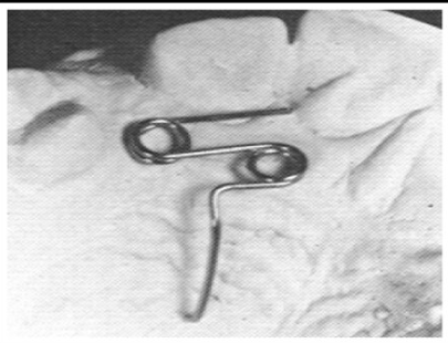
Z-spring22
- A small double helices cantilever spring fabricated in 0.5-0.6mm wire
- Needs good anterior retention
- Activated by pulling spring 1-2mm from baseplate at a 45°
Lecturer — Z-Spring Design
The Z-spring is used primarily for labial movement of incisors and correction of an anterior crossbite.
- The acrylic and clasp design must leave space on the anterior labial side for the tooth to move.
- If the clasp is too close to the tooth, the spring cannot move the tooth effectively.
- Both helices may be activated, and the wire must be bent accurately before the appliance is placed in service.
 |  |
Springs and Screws for Labial Movement of Incisors
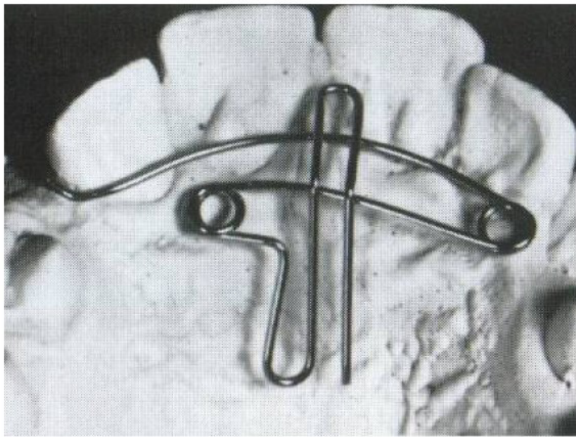
Double cantilever spring23
- Designed to move more than one tooth labially
- Fabricated in 0.7-0.8mm wire
- Activated by pulling spring 1-2mm from baseplate at a 45°
Lecturer — Double Cantilever
A double cantilever spring follows the same principle as the Z-spring but can produce broader movement involving the four incisors.
- Its helices can be activated.
- A thicker wire may be needed because movement is required across more teeth, providing greater force.
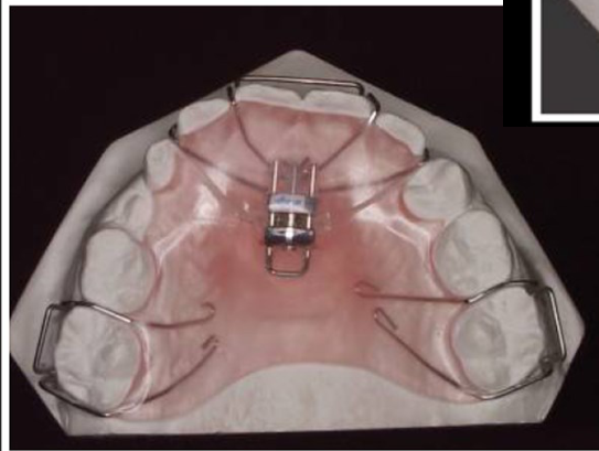
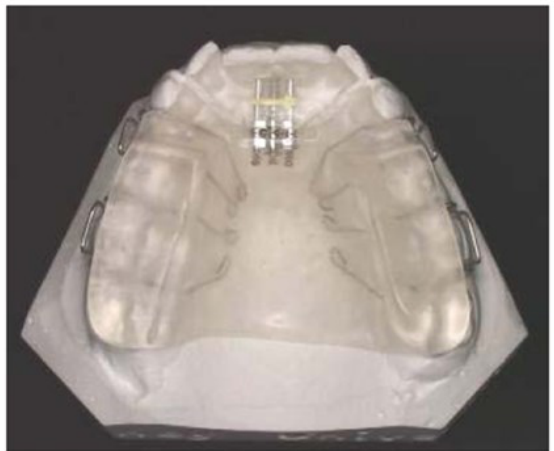
Screw24
- Can be useful where retention is limited
- Incisors clasped for additional retention
- Bulky
- Activated ¼ turn every 3-4 days
 |  |
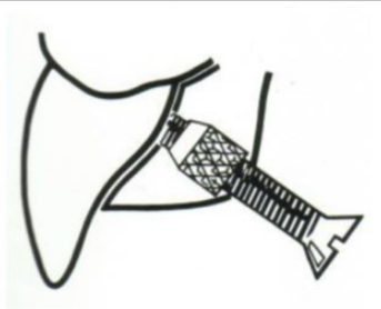
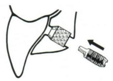
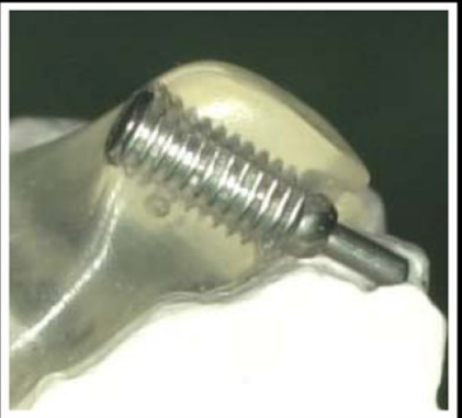
Landin screw25
Lecturer — Landin Screw
The Landin screw uses a piston-like active component beneath the acrylic.
- Activation moves the piston against the tooth intended to move labially.
- In an anterior crossbite, activation moves the incisor forward.
 |  |
 |  |
Springs and Elastics for Palatal Retraction of Incisors
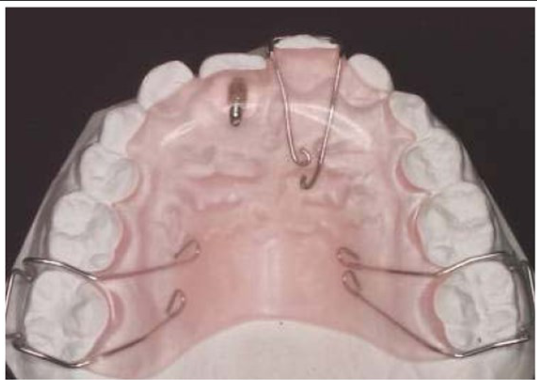
- Also called piston screw
- Used to procline one incisor; direction determined by placement of screw
- Activated by turning with flat plastic about 1mm
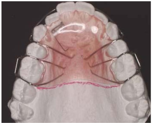
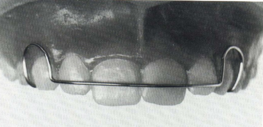
Labial Bow26
- Conventional labial bow can be too stiff for active overjet reduction
- 0.7-0.8mm wire
Lecturer — Labial Bow
A labial bow can act passively as a retainer or be activated to retract incisors and close residual spaces.
- It extends from approximately the middle of the canine toward the distal region and should contact the incisors.
- Adequate acrylic anchorage is required before the bow is activated.
Labial Bow Modifications27
- Added wire to increase the range of the wire (0.7-0.8mm wire)
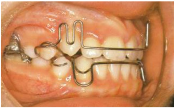
- Roberts retractor
- 0.5mm wire with sheathed tubing distal to the helices
- Useful to retract proclined incisors
- Need adequate sulcus depth
- Followed by Hawley retainer
Lecturer — Roberts Retractor
The thinner Roberts retractor wire increases resilience and range of movement but is easier for the patient to overbend during insertion and removal.
- The patient must be instructed carefully in insertion and removal.
- If the wire is overbent, the retractor may no longer be active.
Tubing
 | 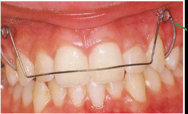 |
Elastics28
- Popular as less visible to retract to reduce overjet
- Can convert labial bow and bend hooks adjacent to canines
- 5/8” 3.5 oz elastics
- Need to trim palatal of base plate
Lecturer — Elastic Retraction
A clasp with a distal bend provides the point from which an intraoral elastic is stretched to retract the incisors.
- The patient must be taught correct placement and followed closely.
- If the elastic slips or is placed incorrectly, it can injure soft tissues or create problems for the appliance and treatment.
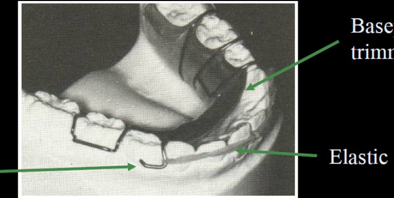
Components for Mesial and Distal Movement
Baseplate trimmed; elastic; labial bow cut and bent.
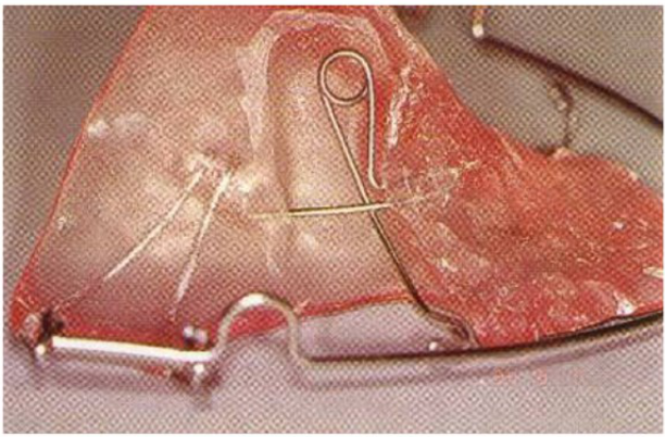
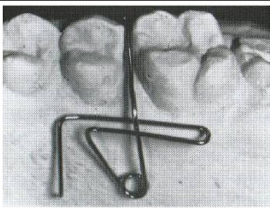
Palatal Finger Spring29
- Activation half a tooth width
- 0.5mm wire
 |  |
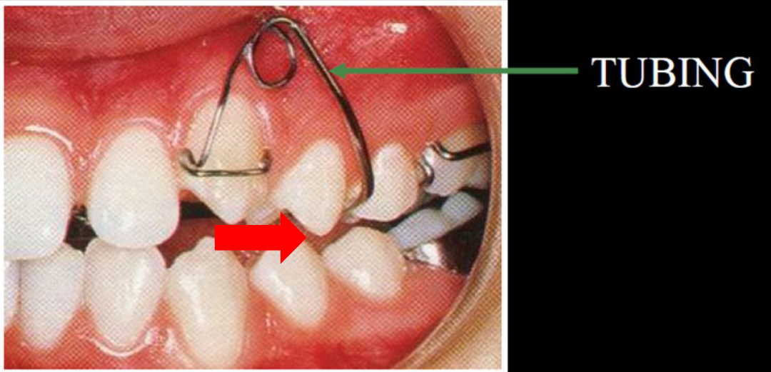
Buccal Canine Retractor30
- 0.7mm wire in a tube
- 1.0mm gives optimal retraction force
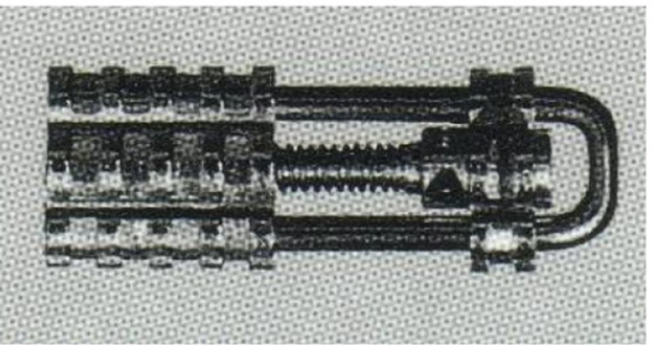
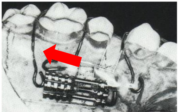
Open Screw31
- Used to CLOSE space
- 1 adjustment per week = (0.25mm space closure)
Lecturer — Open Screw
Each turn of the central jack screw produces approximately 0.25 mm of opening, so four activations produce approximately 1 mm.
- Screw position determines the movement produced.
- A centrally positioned screw can also be used for maxillary expansion.
 |  |
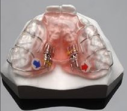
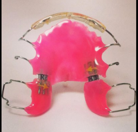
Small Slow Expansion Screw32
- Used to OPEN space
- 1-2 adjustments per week = (0.25-0.5mm space opening)
Lecturer — Slow Expansion
Slow activation is necessary because the appliance depends on clasp retention and acrylic anchorage.
- Even an appliance with four Adams clasps requires gradual activation.
- Two activations produce 0.5 mm of opening in the screw, corresponding to approximately 0.25 mm on each side.
 |  |
Components for Buccal Movement of Premolars and Molars
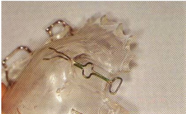
T-Spring33
- Used for single molar or premolar
- Requires good retention to resist displacing effect
- Activated by pulling wire away from acrylic at a 45° angle
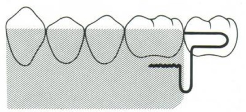
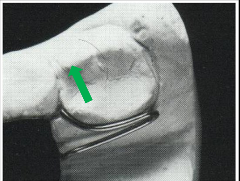
Molar spring34
- Used for buccal movement of molar
- Activated by bending out towards buccal
 |  |
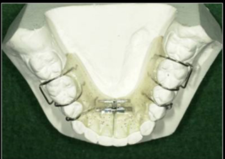
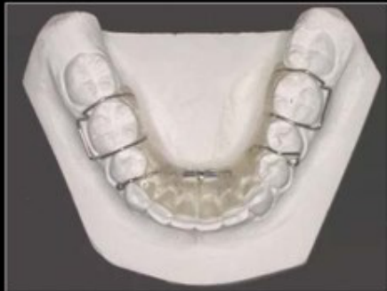
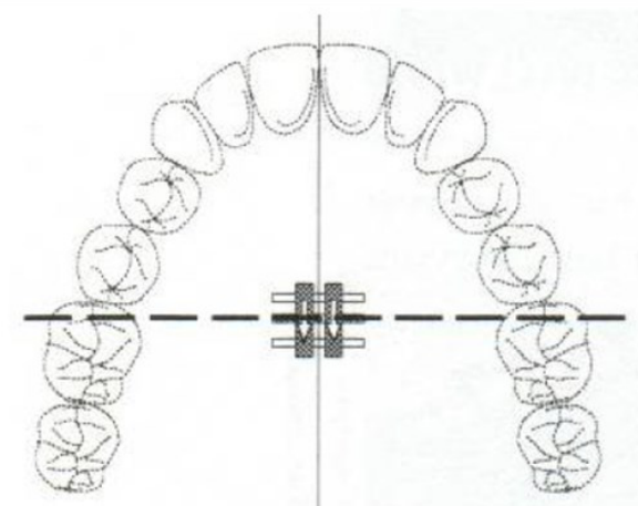
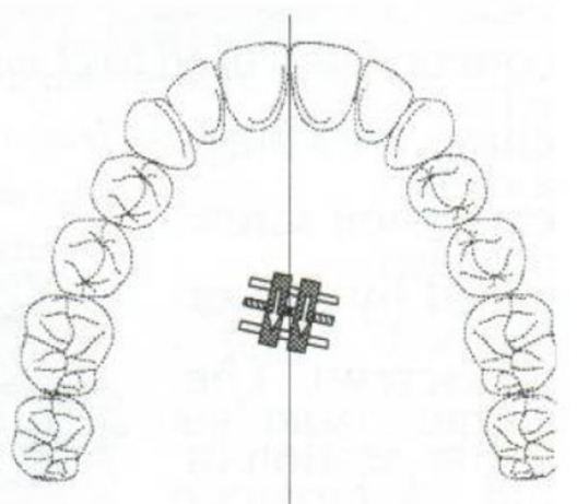
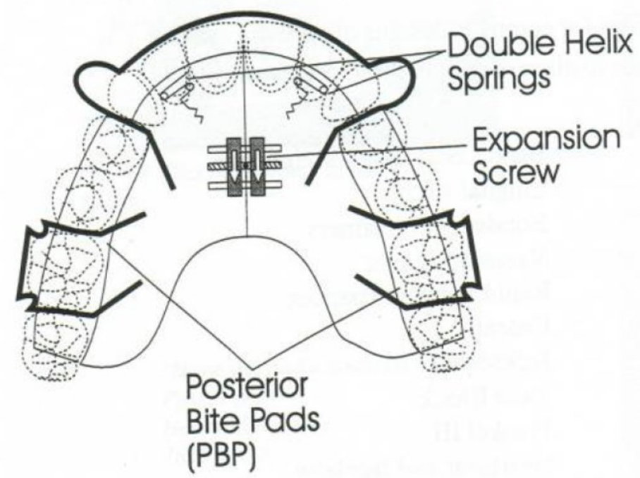
Expansion Appliances and Screw Positioning353637
 |  |
 |  |
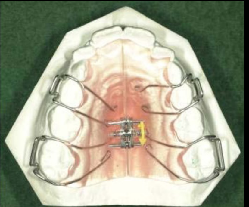
Expansion Appliance38
-
Used for more than one tooth, for example correction of a crossbite by upper arch expansion
-
Activated by one adjustment 1-2 times per week
-
Posterior bite plate may be necessary to increase anchorage
-
Can also be used in the lower arch
-
Activated by one adjustment 1-2 times per week
-
Posterior bite plate may be necessary to increase anchorage
-
Not as effective – limited to dental tipping
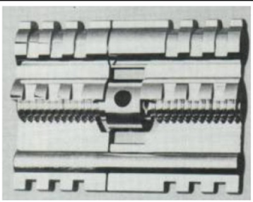
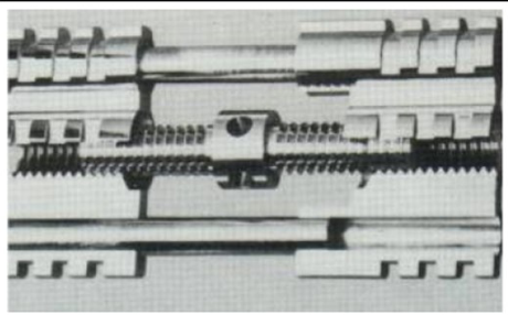
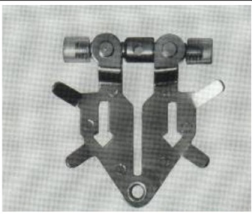
Types of expansion screws39
- Symmetrical bilateral expansion screw
- Fan screw
Fan screw: more expansion anterior/posterior as required.
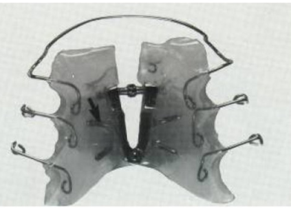
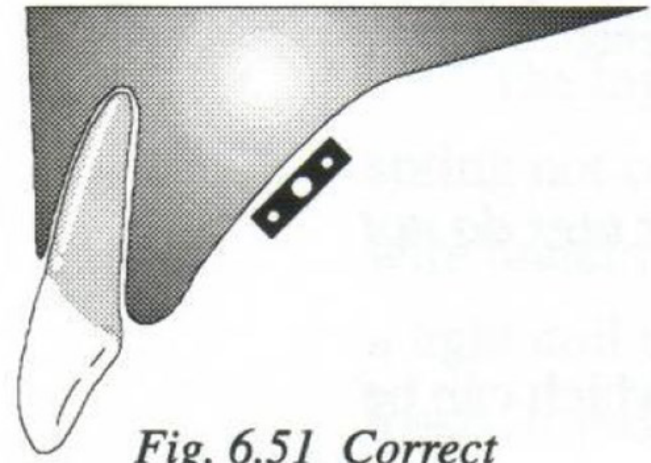
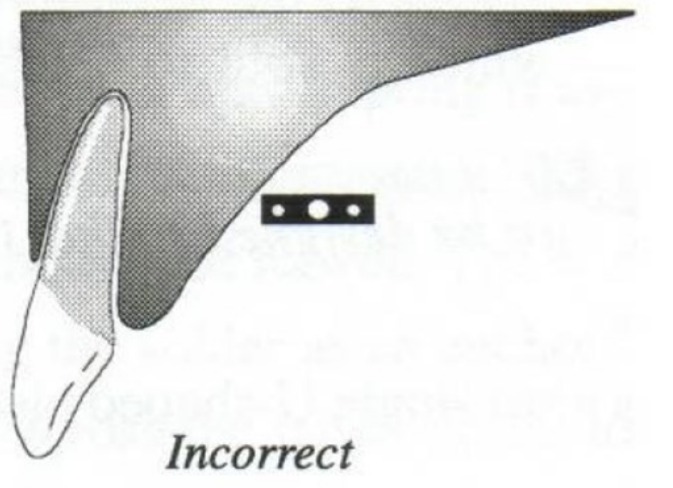
The screw has to be correct in 3 planes of space.
The screw has to be correct in 3 planes of space.
- Correct
- Incorrect: would result in lifting of the appliance off the right side.
 |  |
 |  |
Habit Breaking Cribs4041
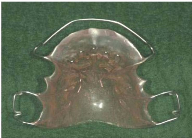
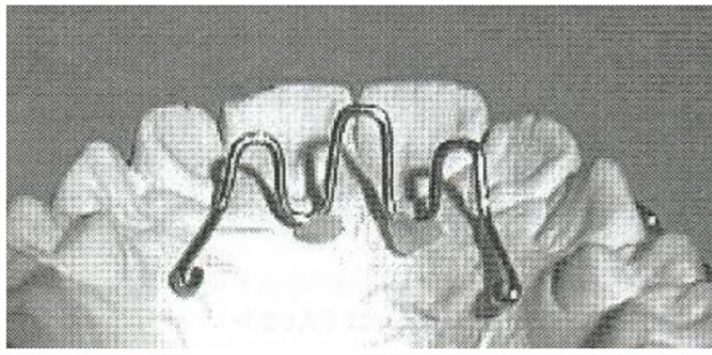
A wire is bent to protrude from the appliance to discourage the child from placement of their digit.
 |  |
 |  |
Bite Opening Appliances
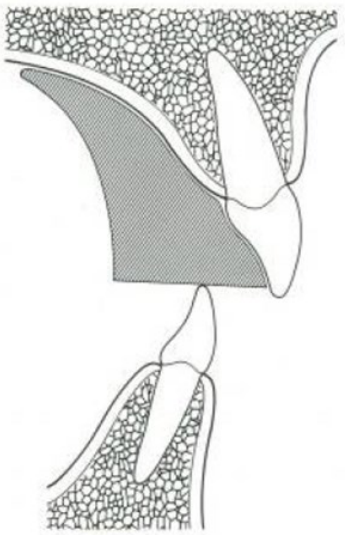
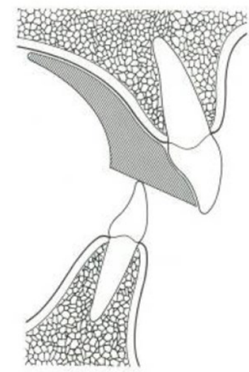
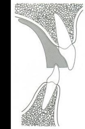
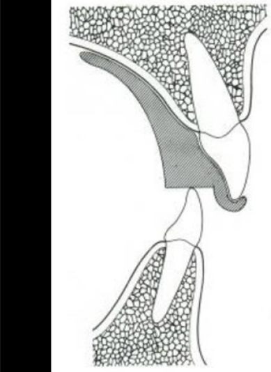
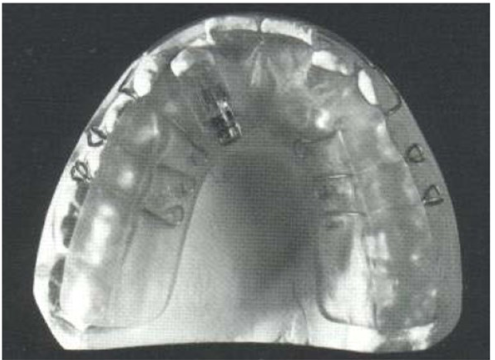
Anterior bite plane42
- Correction in the vertical dimension
 |  |
 |  |
Posterior bite plane43
- Correction in the vertical dimension
- Temporarily open the bite so as to allow a tooth that is in crossbite to be proclined
- Control the vertical development of the posterior teeth (can use attachments for headgear – extraoral traction)
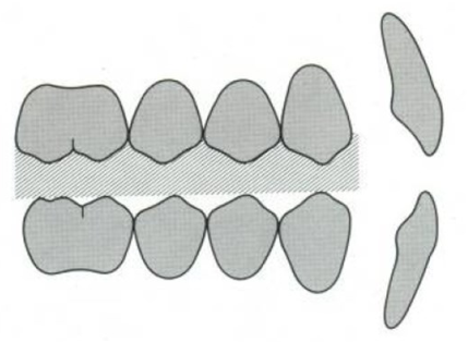
Lecturer — Anterior Bite Plane
An anterior bite plane can reduce a deep overbite by contacting the lower incisors and separating the posterior teeth.
- Posterior eruption may rotate the mandible clockwise.
- The acrylic should be approximately orthogonal to the lower incisors; if inclined, it may act as an inclined plane and procline the incisors instead of permitting eruption.
Lecturer — Posterior Bite Plane
A posterior bite plane may be used in a hyperdivergent patient to control posterior tooth eruption.
- Posterior encapsulation can prevent or limit eruption of the posterior teeth.
 |  |
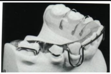
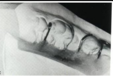
Stabilizing Components
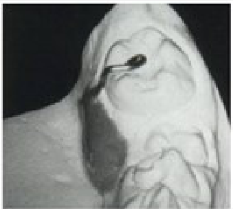
Proximal spur44
- Used to hold space preventing teeth from drifting
 |  |
 |
Retaining the Appliance45
Occlusal rest
- Adds stability to the appliance
Retention = what holds the appliance in the mouth.
- No suction … like full dentures
- Relies on mechanical retention
- That is placing a part of the appliance in an undercut
- Done by various clasps and labial bow
A properly designed and constructed clasp should be passive and exert no force on the tooth except when the appliance is dislodged.
Types of Clasps46
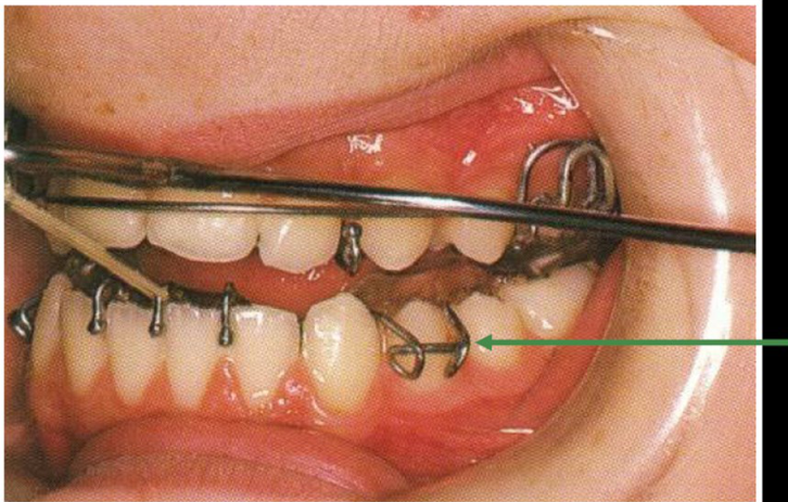
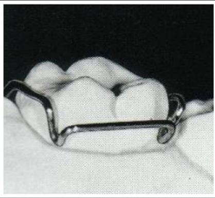
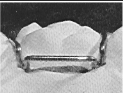
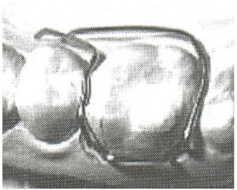
Adams clasp47
- Engages undercuts mesial and distal at the buccal surface
 |  |
 |
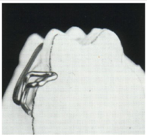
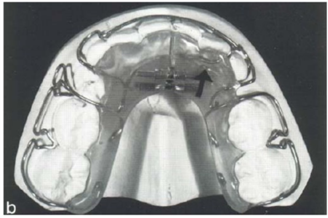
Arrowhead clasp48
- Engages undercuts interproximal undercut
 |  |
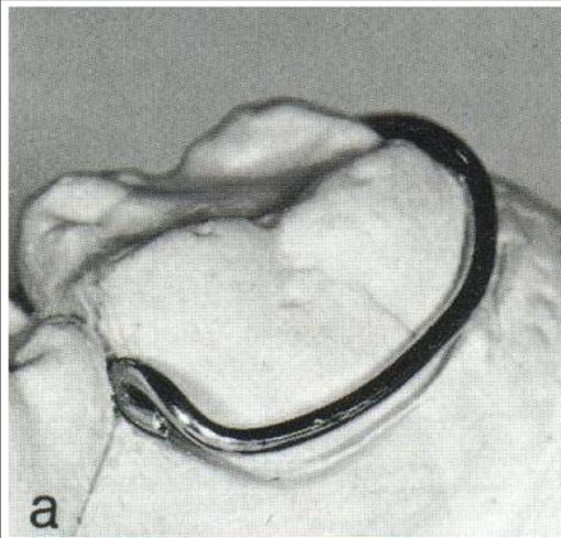
”C” clasp49
- Engages undercuts interproximal undercut
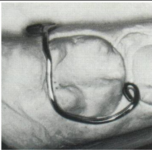
Vertical end
- Engages undercuts interproximal undercut
 |  |
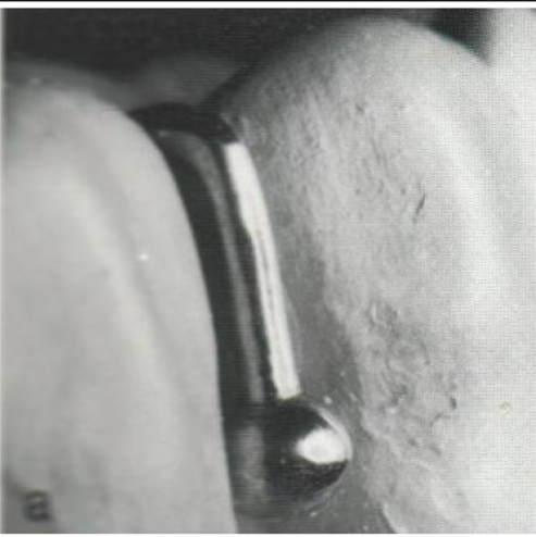
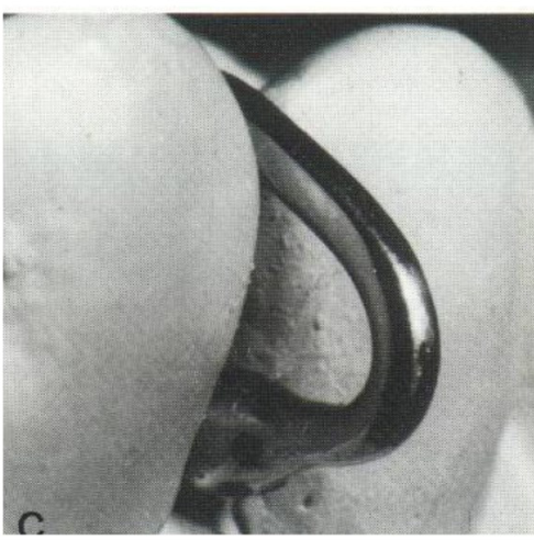
Ball clasp50
- Engages undercuts interproximal undercut
 |  |
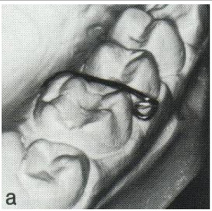
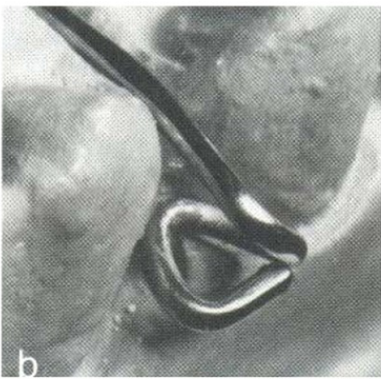
Variations and Other Clasps
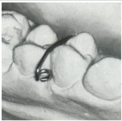
Variations of the Ball clasp51
- Engage undercuts interproximal undercut
Eyelet clasp and triangle clasps
 |  |
 |
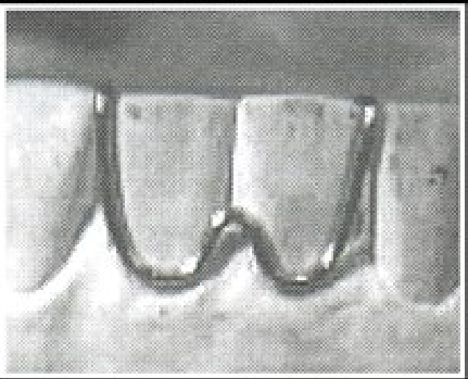
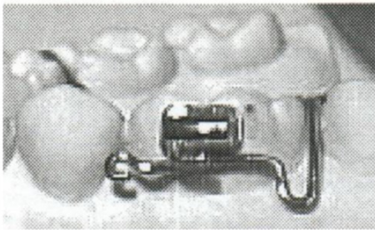
Other clasps52
- Engage undercuts interproximal undercut
 |  |
Anchorage53
- Townsend Clasp
- Other clasp used when fixed appliances in place
The resistance to unwanted tooth movement.
- When we exert force on a tooth, an equal and opposite force is placed on the appliance in the opposite direction.
- This means the unwanted force can move the anchor teeth.
- Therefore when we plan orthodontic tooth movement the reciprocal effects throughout the dental arches must be carefully analyzed, evaluated and controlled.
- The aim is to maximize the desired tooth movement while minimizing the undesirable effects.
Lecturer — Molar Distalization
When moving a molar distally to regain space for a premolar, anchorage is especially important.
- The upper arch permits greater palatal acrylic coverage, whereas the lower arch is limited by the tongue.
- A removable appliance generally cannot regain more than approximately 2 mm of space in this situation.
Ways to improve anchorage54
- Incorporate as many teeth as possible to resist the desired movement
- Maximize the coverage by the baseplate
- Correctly make active components so they work most efficiently (consider point of application, direction and the duration of forces)
- Increase anchorage by the use of inter-maxillary force (elastics) or extra-oral force (headgear)
Baseplate Construction55
The baseplate can be made from:
- Acrylic with a salt and pepper technique
- Plastic with a vacuum forming technique
Lecturer — Baseplate Construction
Construction includes blocking out undercuts, attaching wire components to the cast, applying separating medium, adding monomer and polymer in small increments, polymerizing the acrylic in a pressure pot or closed environment, and trimming and polishing the appliance.
- Should be extended to maximize anchorage and thick enough to give sufficient strength to prevent fracture
- However should not be too thick as it does overly interfere with speech
Communication Between Dentist and Technician56
There needs to be good communication between the dentist and the technician to ensure the appliance is made correctly.
There are two ways to do this:
- Draw directly onto the cast
- Complete a prescription form (sheet)
Lecturer — Laboratory Communication
A general instruction such as “make a removable appliance to regain space” is not sufficient because many designs could achieve that objective.
- Drawings, colour coding, digital-scan notes, photographs, or uploaded files can clarify the intended design more reliably than a clasp name alone.
Draw on the cast57
- Interdental spur or stops
- Screw
- Clasp
- Split baseplate
Fill in a prescription sheet.
Common Problems in Design and Fabrication5859606162
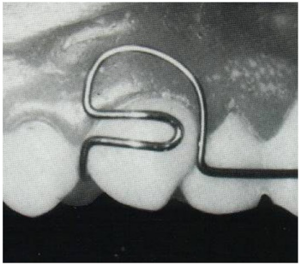
Failure to adapt the acrylic to the occlusal surface.
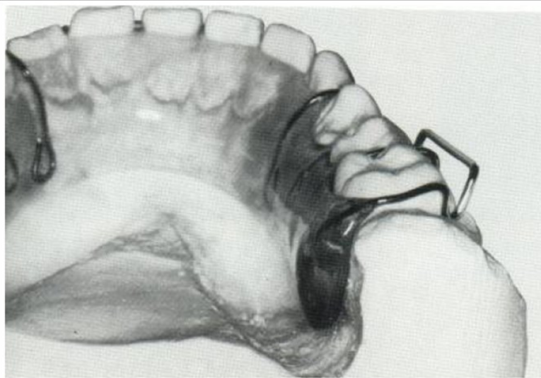
Framework prevents eruption of a tooth.
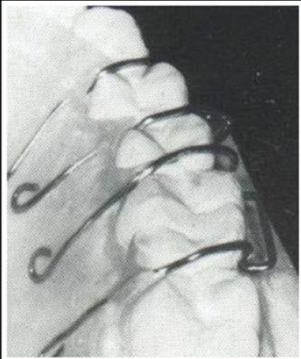
Bridge of the Adams clasp is too large and may interfere with occlusion and be traumatic to the cheek.
Lecturer — Design Failures
If retention is inadequate, activating a spring may dislodge the entire appliance instead of moving the intended tooth.
- Other failures include a distorted or incorrectly bent clasp, an inaccurate model or impression, an obstructed spring, and insufficient space for the intended tooth movement.
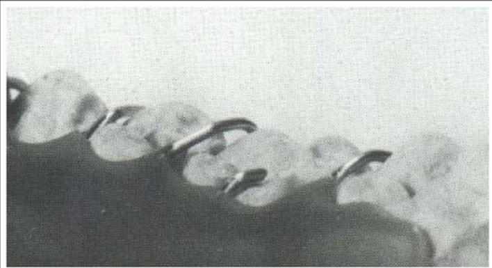
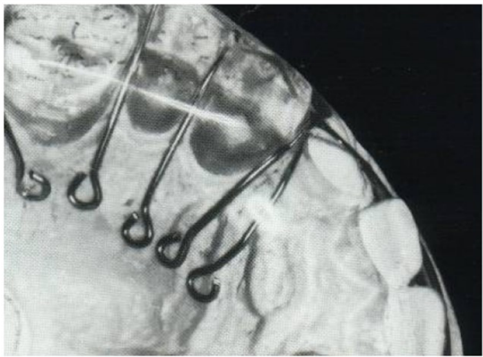
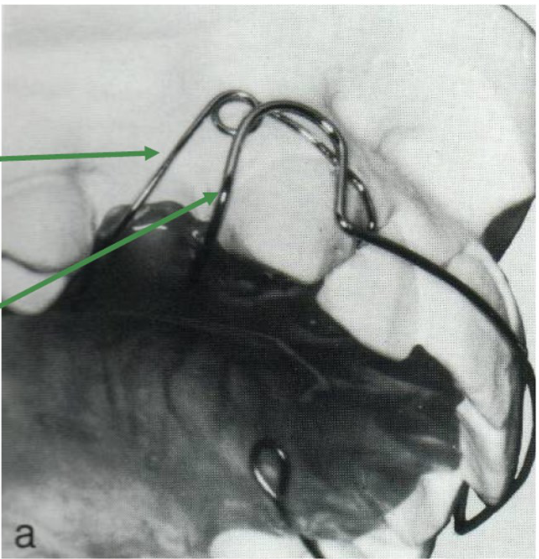
Interference with two aspects of design:
- For example the labial bow will prevent retraction of the canine
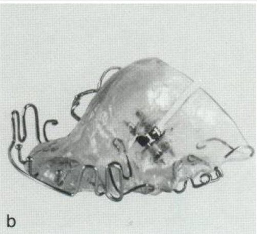
Failure to position the screw correctly63
- For example the screw is placed vertically and will just displace the appliance
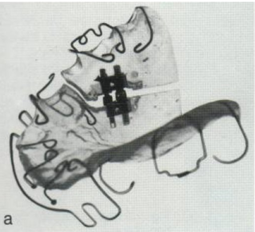 |  |
Wire Bending64
Under construction
J. Mike Razza Orthodontics University of Western Australia - Dental School
What You Need to Know65
- Why use a removable appliance
- Who is involved in fabricating a removable appliance
- Sequence of events in fabrication
- Ideal properties of a removable appliance
- Advantages and limitations of removable appliances
- Principles of design
- Communication
- Wire bending
Lecturer — Wire Bending
Wire bending is necessary for constructing removable appliances.
- Students should understand how wire diameter, spring design, activation, resilience, and repeated bending affect appliance performance.
Ideal Properties of Wire for Removable Appliances66
- Strength to withstand deformation
- Constant force over wide arch of deflection
- High resilience (energy for tooth movement)
- Biocompatible and environmentally stable
- Formable so can bend into hooks
- Joinable (weld or solder)
- Low cost
Lecturer — Wire Resilience
Resilience is the capacity of the wire to store elastic energy and release it over time.
- Resilience can be increased by reducing wire thickness, increasing wire length, incorporating loops or helices, and using an appropriate spring design.
Properties of Stainless Steel Wire67
What type of wire do we use?
18-8 Stainless Steel68
- An alloy of Iron and Carbon
- 18-8 indicates there is 18% Chromium and 8% Nickel with 71% Iron and 0.15% Carbon
- Chromium forms an oxide layer which is in effect what makes stainless steel stainless
Lecturer — Nickel Sensitivity
Nickel stabilizes the austenitic phase, and austenitic stainless steel is suitable for wire bending.
- Patients should be asked about reactions to earrings because nickel sensitivity may be relevant.
- Titanium-based wire may be considered for a patient who cannot tolerate nickel, although it is substantially more expensive.
Properties of Stainless Steel:
- Large Modulus of Elasticity / High stiffness
- Resists deformation
- Produces high forces for small deflection
- Requires frequent activations
Lecturer — Stainless Steel Wire
Stainless steel is commonly used because it is relatively inexpensive and can be soldered to other stainless steel components.
- Its stiffness means that wire design must be used to increase resilience.
- A thinner wire with additional loops can provide a greater range of deflection and lower force.
Properties of Stainless Steel:
Work Hardening69
- The more the wire is bent the more its hardness increases
- Excessive bending will break the wire due to fatigue
- Therefore if it has taken many bends to adapt the wire, start again, as it may break in the mouth which will require a replacement appliance
Lecturer — Work Hardening
Repeated bending creates microstructural changes called dislocations, making the wire harder and more brittle.
- A spring should not be repeatedly bent, unbent, and rebent; corrections should be completed before the appliance is placed in service.
- Excessive work hardening may require a new impression or scan, appliance remaking, and additional clinical and laboratory procedures.
Properties of Stainless Steel:
Heat Sensitivity and Soldering70
Can be soldered.
Stainless steel should never be heated to a point where it glows red hot (sensitive to heat in the range of 700-800°C).
- It will lose its temper and become annealed, which significantly softens the wire.
- The carbon and Chromium combine and are deposited at the grain boundaries, causing the metal to become brittle with reduced resistance to corrosion.
Lecturer — Soldering Heat
Stainless steel can be joined using silver soldering, which melts at approximately 700°C.
- The soldering procedure must be quick because excessive heating removes the mechanical effects of work hardening introduced during manufacture.
- An overheated piece should be discarded and replaced.
Basic Wire Bending Rules71
-
Hold both ends, as small cut-offs can fly across the room.
-
If the cut-off is too short to hold, then place lab cutters against something to control the cut piece to ensure it doesn’t hit anyone.
-
Wear safety glasses at all times.
-
Ensure that wire ends are not sharp.
-
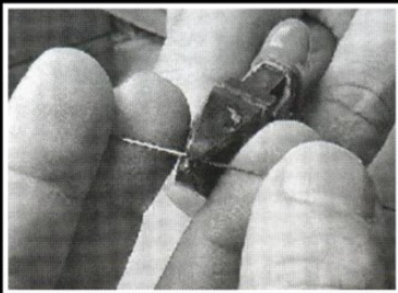
Pliers are used to hold the wire, like a vice.
-
Do not use the pliers to apply force that bends the wire, as it results in excessive wear and possible damage of the pliers.
-
The forces to bend the wire are applied by the fingers and thumb.
Types of Pliers7273
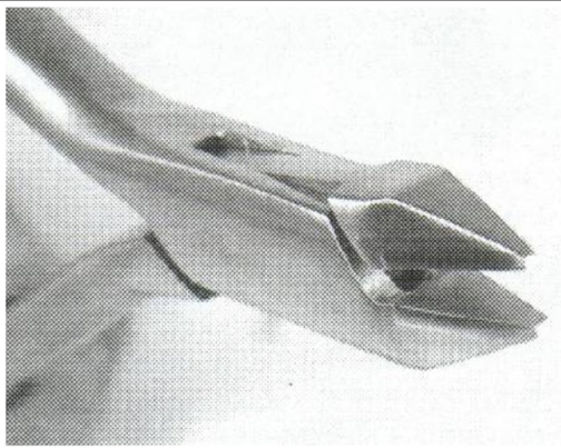
Adams Pliers (Square Jaw)74
- Two square jaws terminating at a 1mm square tip
- Available in a number of sizes to bend wire from light to heavy sizes
- Can be used to place torqueing bends
Lecturer — Adams Pliers
Adams pliers are appropriate for sharp-edged, square-shaped, angular, or square bends.
- They should not be used to form loops or adjust the helices of a Z-spring because repeated corrections can increase work hardening at the same point and the risk of wire failure.
Loop or Spring Forming Pliers75
-
One square, one round jaw
-
Available in a number of sizes to bend wire from light to heavy sizes
-
The stepping allows you to form uniform loops of various sizes
-
Pressing too hard will leave nicks in the wire
-
A 139 plier, with one square and one round tip, may be used depending on the required design.
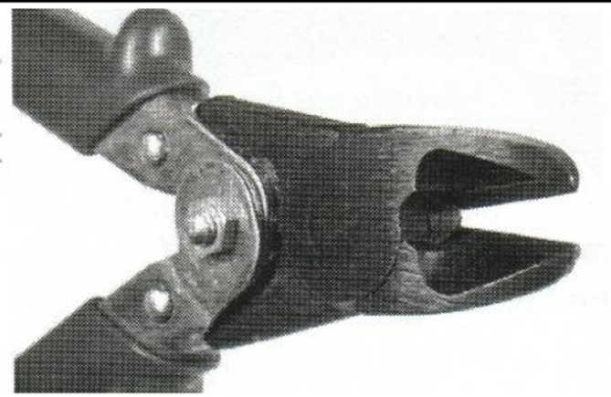
Wire Cutters76
- Orthodontic wire cutters have a hardened tip to cut all materials easily.
Course Limitations Disclaimer77
At the end of this course you DO NOT have the didactic knowledge or clinical skills to treat comprehensive orthodontic cases.
Lecturer — Practical Expectations
Students are expected to understand the principles sufficiently to follow fabrication, recognize appropriate designs, identify construction errors, and communicate effectively with the dental technician.
- They should also recognize problems with retention, anchorage, screw position, and wire bending, and apply wire-bending knowledge during practical work.
- Assistance with wire bending and appliance adjustments is available after the lecture and during practical sessions.
Clinical Cases
Case: Removable appliance with Z-spring for lateral incisor crossbite
Question
Scenario: A study model showing a removable orthodontic appliance designed to correct an anterior crossbite involving a lateral incisor.
What’s shown: An appliance embedded in an acrylic plate featuring a Z-spring and a clasp on the adjacent tooth.
Consider: How the design of the clasp and spring allows for the planned tooth movement.
Answer
Observations:
- The Z-spring is embedded in the acrylic plate.
- There is a clasp (hollow clasp) adjacent to the lateral incisor.
- Space is provided on the anterior and labial part for the lateral incisor to be inclined.
Reasoning:
- To correct the anterior crossbite, the lateral incisor needs space to move labially.
- If the clasp is in close relation to the tooth, it blocks movement, so force must be applied labially with adequate space provided.
- The spring is fabricated with 0.5 or 0.6 mm wire to improve the range and resilience, allowing activation of both helices to change the position of the lateral incisor.
Outcome: The design allows for the correction of the lateral incisor’s position in the anterior crossbite.
Takeaway: When designing a removable appliance for an anterior crossbite, ensure adequate labial space for tooth movement and use an appropriate wire gauge (0.5-0.6 mm) for spring resilience.
Case: Double cantilever spring for incisor movement
Question
Scenario: A clinical photograph showing a double cantilever spring on an orthodontic appliance.
What’s shown: A spring design with helices that spans across the anterior teeth.
Consider: The indication for this spring design and the required wire modifications compared to a standard Z-spring.
Answer
Observations:
- The design is a double cantilever spring.
- It spans across and considers all four incisors.
Reasoning:
- This design achieves broader movement across multiple teeth (all four incisors).
- Because the movement is across more teeth, a thicker wire is needed to increase the amount of force delivered.
Outcome: The appliance achieves broader movement of the four incisors.
Takeaway: A double cantilever spring is used for broader anterior movement and requires a thicker wire to deliver the necessary increased force.
Case: Expansion screws for retroclined central incisors
Question
Scenario: An orthodontic appliance mounted on a model, featuring screws in the anterior part.
What’s shown: An appliance with screws positioned in the anterior acrylic plate, adjacent to retroclined central incisors.
Consider: How the positioning and activation of the screws modulate the required tooth movement.
Answer
Observations:
- The central incisors are retroclined.
- Screws are positioned in the anterior part of the acrylic plate.
Reasoning:
- The screws can be positioned in different places to modulate the specific movement needed.
- Activating the screw increases the separation between the parts of the acrylic plate, applying force to move the incisors labially.
Outcome: The central incisors are moved labially to correct the retroclination.
Takeaway: Expansion screws offer a flexible technique where their placement modulates the specific direction and type of anterior tooth movement.
Case: Landing screw for anterior crossbite
Question
Scenario: A dental study model fitted with a removable appliance featuring a landing screw.
What’s shown: An appliance with a threaded screw and a piston-like active part underneath the acrylic, contacting an incisor in anterior crossbite.
Consider: The mechanism of action of the landing screw in correcting the crossbite.
Answer
Observations:
- The incisor is in an anterior crossbite.
- The appliance features a landing screw with a piston-like component underneath the acrylic.
Reasoning:
- The piston is in direct contact with the tooth to be moved labially.
- Activating the screw drives the piston forward, pushing the central incisors labially to correct the crossbite.
Outcome: The central incisors are moved forward to resolve the anterior crossbite.
Takeaway: A landing screw uses a piston mechanism under the acrylic to directly push teeth labially, effective for correcting anterior crossbites.
Case: Labial bow for closing a diastema
Question
Scenario: A close-up view of the upper part of a removable orthodontic appliance featuring a labial bow.
What’s shown: A labial bow made of 0.7 or 0.8 mm stainless steel wire with loops extending from the canine to the distal part, touching all incisors.
Consider: How the labial bow can be activated to manage residual spaces or a diastema.
Answer
Observations:
- The labial bow is made of 0.7 or 0.8 mm stainless steel wire.
- It features loops and touches all the incisors.
- There is a diastema or residual space present.
Reasoning:
- If passive, the bow acts as a retainer.
- By activating the loops/springs, the bow can be used to close residual spaces or a diastema.
- Sufficient anchorage from the acrylic plate is required to allow the clasp to be activated effectively.
Outcome: The activated labial bow closes the diastema or residual space.
Takeaway: A labial bow can be activated to close spaces, but requires adequate anchorage from the acrylic baseplate to function effectively.
Case: Roberts retractor and modified hollow clasp
Question
Scenario: Clinical and intraoral photographs showing a Roberts retractor appliance and a variant of a hollow clasp.
What’s shown: A Roberts retractor made of 0.5 mm stainless steel wire, and a clasp with a double loop on the canine.
Consider: The advantages, limitations, and patient instructions required for these specific clasp designs.
Answer
Observations:
- The Roberts retractor uses 0.5 mm stainless steel wire.
- The modified hollow clasp features a double loop on the canine instead of a single loop.
Reasoning:
- The 0.5 mm wire in the Roberts retractor increases resilience and range of movement.
- However, the thin wire is prone to over-bending if the patient removes and inserts the appliance improperly, rendering it inactive.
- The double loop on the canine clasp improves retention compared to a single loop.
Outcome: The appliances provide effective retention and movement, provided the patient is well-instructed.
Takeaway: Thinner wires (0.5 mm) increase resilience but require careful patient instruction to prevent over-bending; double loops on clasps improve retention.
Case: Incisor retraction using elastics
Question
Scenario: A clinical photograph showing an orthodontic appliance with a labial bow modified for elastics.
What’s shown: An appliance with a clasp featuring a distal bend, allowing an intraoral latex elastic to be stretched across the anterior teeth.
Consider: The mechanism of retraction and the potential risks associated with this design.
Answer
Observations:
- The clasp has a distal bend to hold an intraoral latex elastic.
- The elastic is stretched across the incisors.
Reasoning:
- Stretching the elastic applies force to retract the incisors.
- There is a risk of the elastic sliding and hurting the patient’s soft tissues.
- The patient must be able to place the elastic properly.
Outcome: The incisors are retracted using the elastic force.
Takeaway: Elastics can be used for incisor retraction on a removable appliance, but require close follow-up and patient instruction to prevent soft tissue injury from slipping.
Case: Space regaining for a mesially drifted first molar
Question
Scenario: A removable orthodontic appliance featuring a modified Z-spring with the active part in the proximal area.
What’s shown: An appliance with a helix and an active proximal part designed to engage a first molar that has drifted mesially following the early loss of a primary molar.
Consider: The design considerations and limitations of using a removable appliance to distalize a molar and regain space for a premolar.
Answer
Observations:
- The first molar has drifted mesially due to the early loss of a primary molar.
- The premolar cannot erupt due to lack of space.
- The appliance uses a modified Z-spring with a helix and proximal active part.
Reasoning:
- Activating the helix moves the first molar distally to regain space for the premolar to erupt.
- Moving a molar backwards requires significant anchorage.
- In the upper arch, the acrylic plate can cover the palate for anchorage. In the lower arch, the plate must be thinner due to the tongue, requiring different clasps to compensate and increase anchorage and retention.
- Limitations include the inability to regain more than 2 mm, especially if the adjacent second molar has also drifted forward and blocks the movement.
Outcome: The first molar is moved distally to open space for the premolar, within the limitations of the appliance.
Takeaway: Removable appliances can distalize mesially drifted molars to regain space, but require careful anchorage design and are limited in the amount of space that can be regained (maximum 2 mm).
Case: Orthodontic appliance clasp interfering with canine eruption
Question
Scenario: An orthodontic case involving a removable appliance and an erupting canine is presented for design evaluation.
What’s shown: A black-and-white photograph of a removable appliance with wire clasps on a dental cast.
Consider: How the current clasp design affects the erupting canine and what modifications should be made.
Answer
Observations:
- The clasp is positioned in a way that prevents the canine from erupting.
Reasoning: If a canine is in eruption, the clasp design must be altered to avoid blocking its path. The clasp can be extended to the premolar area to avoid interference.
Outcome: The design must be changed to accommodate the erupting canine.
Takeaway: When designing a removable appliance, ensure that clasps do not impede the eruption path of developing teeth; modify the clasp extension if necessary.
Case: Upper removable appliance with unadapted Adams clasp
Question
Scenario: A maxillary dental cast with a removable orthodontic appliance is evaluated for fit and retention.
What’s shown: A clinical photograph of a maxillary dental cast showing an Adams clasp on the appliance.
Consider: The adaptation of the Adams clasp and its effect on the appliance’s retention.
Answer
Observations:
- The bridge or buccal face of the Adams clasp on the left side is not adapted and sits far away from the tooth.
- The right side appears to be adequately adapted.
Reasoning: An unadapted clasp provides no retention. Because the left side of the clasp is not in contact with the tooth, the left side of the upper removable appliance will not achieve enough retention, and the plate will not stay in position.
Outcome: The appliance will lack retention on the left side and fail to stay in place.
Takeaway: Proper adaptation of the Adams clasp bridge to the tooth surface is critical for achieving adequate retention of a removable appliance.
Case: Removable appliance design with labial bow interfering with canine retraction spring
Question
Scenario: A wire orthodontic removable appliance is being evaluated for potential design interferences during canine retraction.
What’s shown: A close-up clinical photograph of a wire orthodontic appliance featuring a labial bow and a spring.
Consider: The interaction between the labial bow and the spring used for canine retraction, and how to resolve any interference.
Answer
Observations:
- A labial bow is present to increase retention.
- A spring is intended to retract the canine distally.
- The regular labial bow rests on the distal aspect of the canine, preventing the spring from being activated.
Reasoning: If the labial bow contacts the distal face of the canine, it blocks the activation of the retraction spring. To resolve this, the spring must be kept in place to move the canine distally, and the labial bow must be modified so it does not contact the distal face of the canine.
Outcome: The labial bow design must be changed to clear the distal face of the canine to allow spring activation.
Takeaway: When designing a removable appliance for canine retraction, ensure that the retentive labial bow does not interfere with the activation path of the retraction spring.
Footnotes
-
Original PDF page 1: L8.2 Removable Appliances Construction, p.1 ↩
-
Original PDF page 2: L8.2 Removable Appliances Construction, p.2 ↩
-
Original PDF page 3: L8.2 Removable Appliances Construction, p.3 ↩
-
Original PDF page 4: L8.2 Removable Appliances Construction, p.4 ↩
-
Original PDF page 5: L8.2 Removable Appliances Construction, p.5 ↩
-
Original PDF page 6: L8.2 Removable Appliances Construction, p.6 ↩
-
Original PDF page 7: L8.2 Removable Appliances Construction, p.7 ↩
-
Original PDF page 8: L8.2 Removable Appliances Construction, p.8 ↩
-
Original PDF page 9: L8.2 Removable Appliances Construction, p.9 ↩
-
Original PDF page 11: L8.2 Removable Appliances Construction, p.11 ↩
-
Original PDF page 12: L8.2 Removable Appliances Construction, p.12 ↩
-
Original PDF page 10: L8.2 Removable Appliances Construction, p.10 ↩
-
Original PDF page 13: L8.2 Removable Appliances Construction, p.13 ↩
-
Original PDF page 14: L8.2 Removable Appliances Construction, p.14 ↩
-
Original PDF page 15: L8.2 Removable Appliances Construction, p.15 ↩
-
Original PDF page 16: L8.2 Removable Appliances Construction, p.16 ↩
-
Original PDF page 17: L8.2 Removable Appliances Construction, p.17 ↩
-
Original PDF page 18: L8.2 Removable Appliances Construction, p.18 ↩
-
Original PDF page 19: L8.2 Removable Appliances Construction, p.19 ↩
-
Original PDF page 20: L8.2 Removable Appliances Construction, p.20 ↩
-
Original PDF page 21: L8.2 Removable Appliances Construction, p.21 ↩
-
Original PDF page 22: L8.2 Removable Appliances Construction, p.22 ↩
-
Original PDF page 23: L8.2 Removable Appliances Construction, p.23 ↩
-
Original PDF page 24: L8.2 Removable Appliances Construction, p.24 ↩
-
Original PDF page 25: L8.2 Removable Appliances Construction, p.25 ↩
-
Original PDF page 26: L8.2 Removable Appliances Construction, p.26 ↩
-
Original PDF page 27: L8.2 Removable Appliances Construction, p.27 ↩
-
Original PDF page 28: L8.2 Removable Appliances Construction, p.28 ↩
-
Original PDF page 29: L8.2 Removable Appliances Construction, p.29 ↩
-
Original PDF page 30: L8.2 Removable Appliances Construction, p.30 ↩
-
Original PDF page 31: L8.2 Removable Appliances Construction, p.31 ↩
-
Original PDF page 32: L8.2 Removable Appliances Construction, p.32 ↩
-
Original PDF page 33: L8.2 Removable Appliances Construction, p.33 ↩
-
Original PDF page 34: L8.2 Removable Appliances Construction, p.34 ↩
-
Original PDF page 36: L8.2 Removable Appliances Construction, p.36 ↩
-
Original PDF page 38: L8.2 Removable Appliances Construction, p.38 ↩
-
Original PDF page 39: L8.2 Removable Appliances Construction, p.39 ↩
-
Original PDF page 35: L8.2 Removable Appliances Construction, p.35 ↩
-
Original PDF page 37: L8.2 Removable Appliances Construction, p.37 ↩
-
Original PDF page 40: L8.2 Removable Appliances Construction, p.40 ↩
-
Original PDF page 41: L8.2 Removable Appliances Construction, p.41 ↩
-
Original PDF page 42: L8.2 Removable Appliances Construction, p.42 ↩
-
Original PDF page 43: L8.2 Removable Appliances Construction, p.43 ↩
-
Original PDF page 44: L8.2 Removable Appliances Construction, p.44 ↩
-
Original PDF page 45: L8.2 Removable Appliances Construction, p.45 ↩
-
Original PDF page 49: L8.2 Removable Appliances Construction, p.49 ↩
-
Original PDF page 46: L8.2 Removable Appliances Construction, p.46 ↩
-
Original PDF page 47: L8.2 Removable Appliances Construction, p.47 ↩
-
Original PDF page 48: L8.2 Removable Appliances Construction, p.48 ↩
-
Original PDF page 50: L8.2 Removable Appliances Construction, p.50 ↩
-
Original PDF page 51: L8.2 Removable Appliances Construction, p.51 ↩
-
Original PDF page 52: L8.2 Removable Appliances Construction, p.52 ↩
-
Original PDF page 53: L8.2 Removable Appliances Construction, p.53 ↩
-
Original PDF page 54: L8.2 Removable Appliances Construction, p.54 ↩
-
Original PDF page 55: L8.2 Removable Appliances Construction, p.55 ↩
-
Original PDF page 56: L8.2 Removable Appliances Construction, p.56 ↩
-
Original PDF page 57: L8.2 Removable Appliances Construction, p.57 ↩
-
Original PDF page 58: L8.2 Removable Appliances Construction, p.58 ↩
-
Original PDF page 59: L8.2 Removable Appliances Construction, p.59 ↩
-
Original PDF page 60: L8.2 Removable Appliances Construction, p.60 ↩
-
Original PDF page 61: L8.2 Removable Appliances Construction, p.61 ↩
-
Original PDF page 62: L8.2 Removable Appliances Construction, p.62 ↩
-
Original PDF page 63: L8.2 Removable Appliances Construction, p.63 ↩
-
Original PDF page 64: L8.2 Removable Appliances Construction, p.64 ↩
-
Original PDF page 65: L8.2 Removable Appliances Construction, p.65 ↩
-
Original PDF page 66: L8.2 Removable Appliances Construction, p.66 ↩
-
Original PDF page 68: L8.2 Removable Appliances Construction, p.68 ↩
-
Original PDF page 67: L8.2 Removable Appliances Construction, p.67 ↩
-
Original PDF page 69: L8.2 Removable Appliances Construction, p.69 ↩
-
Original PDF page 70: L8.2 Removable Appliances Construction, p.70 ↩
-
Original PDF page 71: L8.2 Removable Appliances Construction, p.71 ↩
-
Original PDF page 72: L8.2 Removable Appliances Construction, p.72 ↩
-
Original PDF page 76: L8.2 Removable Appliances Construction, p.76 ↩
-
Original PDF page 73: L8.2 Removable Appliances Construction, p.73 ↩
-
Original PDF page 74: L8.2 Removable Appliances Construction, p.74 ↩
-
Original PDF page 75: L8.2 Removable Appliances Construction, p.75 ↩
-
Original PDF page 77: L8.2 Removable Appliances Construction, p.77 ↩