Lecture 6: Impression and Soft Tissue Management1
Impression2
Restorations which fit exactly and can be inserted without any further corrections
Consequences of a Poor Impression
A poor impression, whether conventional or digital, will inevitably result in a poor-fitting restoration.
- ==Guesswork: The dental lab may have to guess the location of margins if they are unclear.==
- ==Distortions: The restoration may fit the lab model but not the actual tooth in the patient’s mouth.==
- ==Inefficiency: This leads to repeated impressions, wasting chair time and materials. A single failed PVS impression can cost over $20 in materials alone.==
- ==Periodontal Issues: Inaccurate margins can lead to plaque retention, increasing the risk of gingival inflammation and recurrent caries. Assessing caries can be difficult under radio-opaque crowns (e.g., zirconia, metal).==
- ==Aesthetic Impact: Distortions can negatively affect the final shape and appearance of the crown.==
- ==Endodontic Success: The quality of the final restoration directly impacts the long-term success of endodontic treatment. Studies show that a poor restoration significantly increases the presence of periapical infections, even with good endodontic work.==
Exact fitting restorations:
- More efficient and faster working
- Aid periodontal prophylaxis, caries
- Aesthetic results
- Prognosis
Table 2. Periradicular status for various combinations of treatment quality
Impression Objectives:3
- Exact duplication of the prepared and uncut tooth beyond the preparation to allow evaluation of location and configuration of finishing line
- Duplicate other teeth and soft tissue to permit proper articulation of the cast and contouring the restoration
Info
This is crucial for the lab to create proper interproximal contacts and natural contours for the restoration.
- Must be free of bubbles specially at finishing line and prepared surfaces
Aim of impression4: produce a dimensionally stable “negative”
- Mould for an analogue model
- Scanned with CAD/CAM model
- Milled model
- 3D printed model
Impression/scanning key steps 5
- Tissue management
- Gingival tissue displacement (if needed)
- Saliva control
Info
This includes managing saliva, blood, and gingival crevicular fluid.
- Adequate impression/scanning technique
Tissue management6
-
Careful preparation
- Hard tissue
- Soft tissue
-
Atraumatic procedure
-
Care must be taken to not damage adjacent teeth, as bleeding can compromise the impression.
-
Well-contoured provisional restoration
Tip
A well-fitting temporary crown with smooth margins prevents plaque accumulation and gingival inflammation, ensuring the tissues are healthy at the final impression appointment. Patients should be instructed on how to floss around temporaries (e.g., pulling floss through the side rather than back up through the contact) to avoid dislodging them.
- Adequate oral hygiene
Tooth Preparation
- Supragingival margins if possible
- Minimally subgingival or intra-crevicular
- Well-defined, smooth and continuous margins
- Well-finished and tidy preparation
- Atraumatic to gingival tissues
Tissue management - supragingival preparation7
Supragingival preparation
Info
Whenever possible, supragingival or equigingival margins are preferred as they make tissue management and impression-taking significantly easier. However, subgingival margins may be necessary for aesthetic reasons (e.g., anterior teeth) or to cover existing deep restorations.
Biologic width8
We risk violation of biologic width! KNOW THIS WORD!
Violation of biologic width
Placing a restoration margin too deep within the sulcus can impinge on the biologic width, leading to:
- Persistent chronic inflammation.
- Clinical attachment loss, including alveolar bone loss and gingival recession.
Assessment: Biologic width can be assessed using bone sounding, where a periodontal probe is used under local anesthetic to measure the distance to the alveolar crest. The sulcus depth is then subtracted from this measurement. A violation is diagnosed if the resulting distance is less than 2 mm.
Margin location
- If the margins have to be subgingival it should only be placed intracrevicularly
- Maximum depth around 0.7 mm
Info
Subgingival margins are associated with a higher risk of gingival inflammation due to factors like defective margins, surface roughness, and improper crown contour.
Bone sounding biologicalwidth
- bone sounding is sounding to the bone (i.e. probing to the bone and measuring the probing depth to bone) when you subrtract the sulculs area Based on bone sounding, patients can be categorized into three types:
- ==Normal Crest (85% of patients): The measurement from the gingival margin to the bone crest is 3-4.5 mm. These tissues are stable and can tolerate a subgingival margin of about 0.5 mm without adverse effects. They recover well from minor trauma, such as from a retraction cord.==
- ==High Crest (2% of patients): The measurement is less than 3 mm. The bone is high, meaning the biologic width is narrow. Placing a margin subgingivally in these patients will almost certainly impinge on the biologic width, leading to persistent inflammation.==
- ==Low Crest (13% of patients): The measurement is greater than 4.5 mm. These patients have a large biologic width. The attachment is fragile and susceptible to damage from retraction cords, often resulting in gingival recession as the tissue heals back to a “normal crest” position.==
Margin placement guidelines9
The margins of the restoration can be positioned 0.5 mm below the gingival tissue crest if the probing depth of the sulcus is 1.5 mm or less.
Note
These guidelines apply to normal crest patients.
If the sulcus depth is more than 1.5 mm, then the margins of the restoration should be inserted in the sulcus at a depth that is half its probing depth. Lastly, a gingivectomy may be enacted to extend the tooth and design a 1.5 mm sulcus if the probing depth of the sulcus is greater than 2 mm.
Tip
This must be weighed against aesthetic concerns, especially in the anterior region.
Normal crest – preparation & tissue management10
Tissue management11
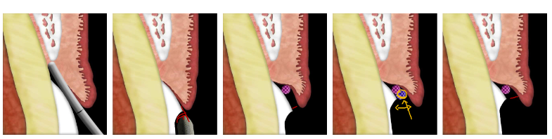
- you want the impression to go down slightly into the sulcus, that way the lab can have a clear picture of where the margin ends !
- Gingival Retraction Technique for Soft Tissue Impressoins
Gingival displacement12
Aims
- Enlargement of gingival sulcus
- Tissue deflection horizontally and vertically to display the margin and root surface
- Finishing line for the restoration
- Development of adequate emergence profile
- Control of gingival bleeding and exudate
Methods of gingival displacement13141516
Mechanical displacement
- Retraction cord
- Copper band
Chemicals
- Astringent: aluminium chloride, ferric sulfate
- Adrenaline – transient ischemia and epithelial tissue shrinkage
Combined
- Retraction cord + chemical
- Expasyl (Kerr)
Surgical widening
- Electrosurgery
- Laser
Mechanical displacement17
Mechanical displacement: Retraction cord
Cord is packed into sulcus stretching the circumferential periodontal fibers 0.3–0.4 mm
Types1819
- Braided
- Knitted
- Twisted
- Medicated and nonmedicated
- Knitted cords (e.g., Ultrapak) are commonly used.
Cords come in various sizes (e.g., 000, 00, 0, 1, 2) to suit different sulcus depths and tissue biotypes.
A specialized instrument is used to place the cord into the sulcus.
- Can have a serrated or non-serrated tip. Serrated tips help grip the cord, but require a specific technique to avoid pulling the cord back out.
- A plastic instrument can also be used.
Medicated Retraction Cords
ultrapak cords normally come unmedicated but ultrapak-E has epinephrine which is medicated!
Cord packing technique2021
Technique description
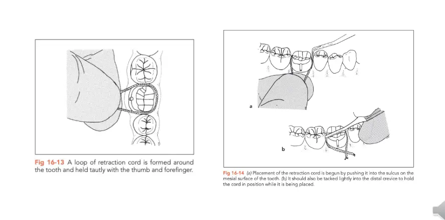
- Fig 16-13: A loop of retraction cord is formed around the tooth and held tautly with the thumb and forefinger.
- Fig 16-14: (a) Placement of the retraction cord is begun by pushing it into the sulcus on the mesial surface of the tooth. (b) It should also be tacked lightly into the distal crevice to hold the cord in position while it is being placed.
- The technique involves a rotational, tucking motion, not a straight up-and-down push.
- The instrument should be angled towards the tooth and slightly towards the already-packed portion of the cord.
- Cut a length of cord approximately 1.5 times the circumference of the tooth to allow for overlap and proper packing.
- The ends of the cord should be left in an easily accessible area, such as the buccal or lingual surface, not interproximally.
Cord techniques22
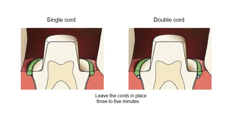
- Single cord
- Double cord
Leave the cords in place three to five minutes (as per the manufacturers instructions)
Single vs. double cord232425
- Single cord
- Double cord
- 1st cord: vertical retraction
- 2nd cord: horizontal displacement
Double cord technique explained
- A thin cord (e.g., 000 or 00) is placed first, deep into the sulcus and completely below the margin. This cord provides vertical displacement and remains in place during the impression.
- A larger cord (e.g., 0 or 1) is packed on top of the first cord. This provides horizontal displacement.
- The top cord is left in place for approximately 5 minutes and then removed just before injecting the impression material.
GRACIS et al. 2001
| Single cord | Double cord |
|---|---|
| Indication: - Shallow sulcus - Thin periodontium | Indication: - Deeper sulcus - When superior control of bleeding/fluid is needed |
| Advantages: - Least traumatic - Limited risk for gingival recession | Advantages: - Excellent lateral displacement - Superior control of bleeding/fluid |
| Disadvantages: - Haemorrhage - Exudate | Disadvantages: - More time-consuming - More traumatic to tissues - Can lead to unpredictable gingival response in high or low crest patients |
Info
The goal is to retract the tissue to allow impression material to flow into the sulcus and capture the entire margin edge, providing the lab with a clear finish line.
Chemical displacement: Hemostatic agent26
Metallic salts
- Causing transient ischemia
- Shrinkage of gingival tissues
- Reduce flow of gingival fluids
Examples:
- Aluminum chloride (Hemadent)
- Aluminum sulfate
- Potassium sulfate
- Ferric chloride
- Ferric sulfate (Astringedent)
Adrenaline
- Can cause tachycardia
Caution
Use with care in patients with known sensitivity or cardiovascular disorders, as it can elevate blood pressure and heart rate, especially if applied to lacerated tissue.
Haemostasis - Expasyl27
- Expasyl
- Aluminium chloride with kaolin
- Dispensed from a syringe
- Expands on setting
- Left for 1-2 minutes
- Washed away with water spray
Info
Expasyl provides both chemical and mechanical displacement. The kaolin clay in its composition expands as it sets, providing mechanical retraction. It can also be used in combination with a small retraction cord placed at the base of the sulcus.
- Traxodent
- Aluminium chloride paste
Expasyl2829
- you can combine expasyl with retraction cord!
Surgical Techniques
-
Remove the inner epithelial lining for better access to finish line, and control of haemorrhage
-
Risk of permanent damage
- Recession
-
Avoid for thin gingiva
-
Can be used to cauterize bleeding areas to improve visibility.
Examples
- Electrosurgery
- Laser
Electrosurgery30
Advantages:
- Lower cost than lasers.
- Electrosurgery cuts rapidly when compared to a diode laser.
- With proper intensity, immediate hemostasis.
- After cutting, the wound is nearly painless.
Disadvantages:
- Contraindicated in patients with any electrical device (PACEMAKERS!)
- You must anesthetize patients
- Burning smell
- Risk of overcutting
- Because of high heat production while cutting, electrosurgery should not be used around implants
Laser31
Advantages:
- Minimal local anesthetic needed,
- Does not harm dental hard tissue.
- Can be used around implants (some laser produce heat)
- Can be used around full metal, PFM crowns, amalgam or gold alloy restorations.
Disadvantages:
- Cost
- Cuts much slower than electrosurgery.
- Cutting large pieces of soft tissue is time consuming
- Danger of laser beam
- Requires special protective eyewear for the patient and clinical team.
Saliva Control32
- Absorbents: block salivary ducts
- Cotton rolls
- Use cotton rolls to retract the tongue and cheeks.
- Absorbing cards
- Saliva evacuator
- Local anesthesia: controls blood and saliva
Impression Technique33
Impression timing
- Inflamed gingivae are by definition swollen
- Impossible to prepare a predictable intracrevicular margin
- Impressions difficult due to uncontrolled haemorrhage
- As soon as periodontal resolution occurs there will be recession
- Therefore, achieve gingival health before embarking on definitive impressions 3-4 weeks with provisional restoration
Note
If tissues are inflamed, swollen, or friable (bleed easily), it is best to place a well-fitting provisional and allow the tissues to heal for several weeks before re-appointing for the definitive impression. This avoids capturing a distorted tissue shape and prevents the final margin from being exposed after healing and recession.
Impression Materials34
Materials for indirect restorations
- PVS – Poly Vinyl Siloxane
- Polyether
Qualities353637
- Dimensional accuracy
- Dimensional stability
- Wettability
- Contact Angle
- Elastic recovery
- Flexibility
- Ease of handling
- Tear Strength
- Cost
Dimensional accuracy:
- Polyvinyl siloxane (PVS) and polyether impression materials remain dimensionally accurate for 1 to 2 weeks
Hydrophilic vs Hydrophobic
- Hydrophobic materials such as PVS may have voids if there is improper moisture control.
- Polyether materials are hydrophilic and may better cope with the moisture in the oral environment
Dimensional stability:38
- “The dimensional stability of an impression material reflects its ability to maintain the accuracy of the impression over time”
- Both polyether and PVS are dimensionally stable compared to alginates
Warning
Alginate is very unstable and must be poured immediately.
Wettability:39
- “Wettability of an impression material relates to the ability of the material to flow into small areas”
- Materials with a high wetting angle do not flow easily into small crevices and are poor candidates for use in fixed prosthodontics. Materials with a low wetting angle flow extensively.
Contact angle:
- “Impression materials with low contact angle enable dental stone to flow easily, and relatively bubble-free casts are produced. Materials with high contact angle require more careful pour technique and attention to produce accurate casts”
Elastic Recovery and Flexibility:4041
- Materials must distort to allow removal from undercuts
- We want a material to have good elastic properties to allow recovery and minimise plastic deformation
Info
Elastic Recovery is the ability of the material to return to its original shape after being deformed during removal from undercuts. A high elastic limit is desired to prevent permanent (plastic) deformation.
- PVS superior to polyether
- Flexible materials are easier to remove from the mouth
- There HAVE been cases of PVS impressions STUCK in a patient’s mouth.
- Polyethers are EVEN MORE rigid
- Alginate the least rigid.
plastic deformation
- we want something ot have a high elastic limit as we don’t want it to deform
Ease of handling:42
- Prefer materials are that easy to work with in everyday clinical situations
- Thixotrophy
Info
Thixotropy is a desirable property where the material becomes more fluid when sheared (e.g., injected from a syringe) but remains viscous enough not to slump off the tray.
Tear strength:43
- “The tear strength of an impression material relates to how resistant a particular material is to tearing after setting”
Note
Polyether has a very high tear strength, PVS is moderate, and alginate is very low.
Types of Dental Materials (Historical Order)44
- Reversible hydrocolloid (Alginate is irreversible hydrocolloid)
- Polysulfides
- Condensation silicon
- Polyether
- Addition silicon
Reversible hydrocolloids45
- Eg. Agar which is able to be melted to a gel like consistency, then cooled to form a more solid material
- Requires special materials to prepare for the impression as well as a tray capable of cooling the agar to “set” it
- Excellent dimensional accuracy if poured immediately
Irreversible hydrocolloids46
- Alginate powder consists of calcium sulfate dehydrate, soluble alginate, and sodium phosphate
- Setting of alginate: Calcium ions from the calcium sulfate dehydrate react preferentially with phosphate ions from the sodium phosphate (retarder to slow setting and increase working time). After the phosphate ions are depleted, the calcium ions react with the soluble alginate to form insoluble calcium alginate, which with water forms the irreversible calcium alginate gel.
- Moderate dimensional accuracy but very poor dimensional stability
- Low tear strength
Polysulfides47
- Supplied as a 2 paste system:
- Base: polysulfide polymer (terminal/side chain −SH groups), titanium dioxide, zinc sulfate, copper carbonate, or silica.
- Accelerator (catalyst): lead dioxide with other substances, such as dibutyl or dioctyl phthalate, sulfur, and magnesium stearate and deodorants.
- Sets by oxidation of the −SH groups, which results in chain lengthening and cross-linking and gives it elastomeric properties.
- Better tear strength compared to hydrocolloids
- Low to moderately hydrophilic, so could work in low blood/saliva environments
- However unpleasant odor and long set time (~10mins)
Condensation silicons48
- Improvement over polysulfides as it is mostly odourless
- Greater dimensional stability compared to hydrocolloids but not as great as polysulfides
- As a condensation silicon, water is released as a by product. This can cause dimensional accuracy/stability issues from evaporation
- Very hydrophobic
Polyether49
- Polyethers also consist of a base and catalyst system:
- Base: long-chain polyether copolymer with alternating oxygen atoms and methylene groups (O-[CH₂]ₙ) and reactive terminal groups.
- Catalyst paste has a cross-linking agent (aliphatic cationic starter) and filler and plasticizers. Polyethers involve the reaction of the polyether-containing imine ringed side chains with a reactant that opens the rings and causes chain lengthening and cross-linking to form a polyether rubber.
- Acceptable setting time of ~5 minutes
- High tear strength, however material is extremely stiff, hence can be difficult to remove from areas of undercuts.
- Can be poured 1-2 weeks after impression from excellent dimensional stability
- Potential allergy/sensitivity issues
PVS50
- Very popular material for impressions
- Setting: linking of vinyl siloxane in the base material with a hydrogen siloxane via a platinum catalyst
- Polyvinyl siloxanes have improved dimensional accuracy compared to condensation silicones.
- Due to by product of hydrogen gas instead of water. Newer products have “Scavengers” that prevent the escape of gas at the polymer-stone interface.
- Stiffness less than polyether allows easier removal from mouth
- Latex gloves (Sulphur compounds) may inhibit set.
- Moderately high contact angle, so sometimes surfactant sprays used to encourage flow of stone during pouring.
Impression Techniques51
- Single stage
- Two Stage
- Spacer or No Spacer
- spacer is recommended so that the impression is more accuracte
Monophase5253
- preparation with retraction cord
- preparation covered with impression material
- tray inserted with the same impression material
NOT RECOMMENDED DUE TO LOWER DEFINITION
**Dualphase – Lightbody & Heavybody
This is the recommended single-stage technique.
- ==Light body (low viscosity) is syringed around the preparation to capture fine detail.==
- ==Heavy body (high viscosity) is loaded into the tray to provide support and pressure.==
- The two materials bond and set together in the mouth.
**
Dualphase – “Putty Wash”54
- preparation with retraction cord
- preparation covered with lightbody (LB) material
- tray inserted with putty material
One-step putty impressions can have significantly lower accuracy compared to two step impressions
Two-step impression with Putty55
- preparation with retraction cord
- Impression with putty
- Putty cut-out
Tip
Space is created for the wash material, either by cutting away some putty around the prep or by using a plastic spacer during the initial impression.
- Preparation / putty cut-out covered with lightbody (LB)
- Good accuracy
1-stage vs 2-stage56
- Significant differences seen on some surfaces of the impressions
- However both impression techniques are clinically acceptable (marginal gap <120um)
Research Article Accuracy of the One-Stage and Two-Stage Impression Techniques: A Comparative Analysis
Clinical steps5758
Intraoral custom tray try-in
- Check for clearance & comfort
- Adjust if required
- Tray adhesive application
- Adhesive must be applied 15 minutes prior to impression
- Extend the adhesive over edge of tray to the outer surface of the tray
Tip
The adhesive should be allowed to dry for approximately 15 minutes until it is tacky to ensure the impression material does not separate from the tray upon removal.
Gingival displacement
- Isolate prepared teeth (free from saliva and blood)
- Cut sufficient cord length
- Wet the cord in astringent
- Loop the cord around the tooth and gently insert it in the sulcus
- Avoid overpacking
- Dry the teeth (do not desiccate)
- Evaluation
- Visualize all the margins of the preparation
- No soft tissue folding over the cord
Impression material mixing:59
- If using “cartridge” system,
- Extrude a little impression material first
- Ensures an even mix of material & no blockage in the cartridge
- If using Putty (addition silicon):
- Latex gloves may inhibit setting
- Equal amount of base and catalyst
Loading the tray:60
- Clinician to apply light body material on the tooth whilst an assistant loads the medium/heavy body in the tray.
- Load adequate amount of material in the tray (just below the height of the tray)
- Do not lift the tip of impression material cartridge out from the loaded material
- Be mindful of total setting time
Tip
Keep the mixing tip submerged in the material to avoid incorporating air bubbles.
Intra-oral material application:61
- Remove second cord in double cord retraction technique, rinse off expasyl
- Adequately dry the preparation, ensure good isolation (tongue etc)
- Inject material around tooth
- Start from the hardest area (likely interproximals)
- Do not lift tip from impression material
- Inject on top of the margins/sulcus areas
- One direction
- Cover the entire prep and part of the adjacent teeth
- Optional: Air thin the material with triplex
Tip
Keep the tip of the syringe submerged in the material and move in one continuous direction around the preparation to prevent bubbles.
Tray insertion62
- Position tray into correct position in mouth first
- Clear lips from tray
- Using one continuous and slow seating movement of the tray into correct area
Tip
Seat the tray with a slow, continuous movement from back to front. This directs excess material forward, away from the patient’s throat. Hold the tray steady for the full manufacturer-recommended setting time (e.g., 5 minutes).
Tray removal63
- Hold tray in mouth until impression is set
- Optimum removal of impression tray:
- upper jaw - loosen tray on opposing side
- lower jaw - loosen tray on prep side.
- front teeth - both sides at the same time.
A guideline for excellent impressions in theory and practice - 3M
Impression Inspection64
- Detailed, accurate occlusal surfaces
- Cusps are sharp
- Tray doesn’t show through
- Distal surfaces of molars are captured
- More than half of each molar is visible
- No bubbles, voids, thin walls, shifts, or double imprints that compromise dental anatomy
- All gingival margins are defined & clear
- Includes at least 3–4 mm of buccal & lingual surfaces outside gingival margin
- Uniform layer of material
- Impression material is intact
- No damage, warping, or separation of light & heavy material
Quote
If you, the clinician, cannot clearly identify the margin on the impression, the lab will not be able to either.
Gagging Patients?65
-
Explain procedure (esp. if likely to gag)
-
Use special tray & less material (don’t apply material on the palate for fixed pros)
-
Have suction and mouth mirror ready to remove excess from posterior border
-
Sit patient up
-
Instruct them to lean forward to prevent material from flowing down their throat.
-
Reassure them but explain that the tray cannot be removed until it is fully set.
-
Do not remove once seated even if you think unsatisfactory
-
Reassure patient
Trouble Shooting6667
-
Bubbles
- ==Cause: Moisture/blood contamination or incorporating air during material application.==
- ==Solution: Ensure a dry field with good hemostasis. Keep the syringe tip submerged in the material during application.==
- ==Cause: Moisture/blood contamination or incorporating air during material application.==
-
Drag lines
- ==Cause: The material began to set before the tray was fully seated, or the tray moved during setting. This indicates you are not working fast enough.==
- ==Solution: Improve workflow efficiency. Have all materials ready to go.==
- ==Cause: The material began to set before the tray was fully seated, or the tray moved during setting. This indicates you are not working fast enough.==
-
Marginal Tears
-
Incomplete set
- ==Cause: Removing the impression too soon before it was fully set; contamination with latex/sulfur; or an incorrect mix ratio from a blocked cartridge.==
- ==Solution: Time the set accurately. Use nitrile gloves. Bleed the cartridge before use.==
Triple Trays68
Allows for registration of the upper and lower arch simultaneously. However not recommended due to distortion of material
Note
They may have limited use in specific situations, such as for a single crown when a patient has very limited opening.
Footnotes
-
Original PDF page 1: F6 ImpressionsSoftTissue, p.1 ↩
-
Original PDF page 3: F6 ImpressionsSoftTissue, p.3 ↩
-
Original PDF page 4: F6 ImpressionsSoftTissue, p.4 ↩
-
Original PDF page 5: F6 ImpressionsSoftTissue, p.5 ↩
-
Original PDF page 6: F6 ImpressionsSoftTissue, p.6 ↩
-
Original PDF page 7: F6 ImpressionsSoftTissue, p.7 ↩
-
Original PDF page 8: F6 ImpressionsSoftTissue, p.8 ↩
-
Original PDF page 9: F6 ImpressionsSoftTissue, p.9 ↩
-
Original PDF page 14: F6 ImpressionsSoftTissue, p.14 ↩
-
Original PDF page 15: F6 ImpressionsSoftTissue, p.15 ↩
-
Original PDF page 16: F6 ImpressionsSoftTissue, p.16 ↩
-
Original PDF page 17: F6 ImpressionsSoftTissue, p.17 ↩
-
Original PDF page 18: F6 ImpressionsSoftTissue, p.18 ↩
-
Original PDF page 19: F6 ImpressionsSoftTissue, p.19 ↩
-
Original PDF page 20: F6 ImpressionsSoftTissue, p.20 ↩
-
Original PDF page 21: F6 ImpressionsSoftTissue, p.21 ↩
-
Original PDF page 22: F6 ImpressionsSoftTissue, p.22 ↩
-
Original PDF page 23: F6 ImpressionsSoftTissue, p.23 ↩
-
Original PDF page 24: F6 ImpressionsSoftTissue, p.24 ↩
-
Original PDF page 25: F6 ImpressionsSoftTissue, p.25 ↩
-
Original PDF page 26: F6 ImpressionsSoftTissue, p.26 ↩
-
Original PDF page 27: F6 ImpressionsSoftTissue, p.27 ↩
-
Original PDF page 28: F6 ImpressionsSoftTissue, p.28 ↩
-
Original PDF page 29: F6 ImpressionsSoftTissue, p.29 ↩
-
Original PDF page 30: F6 ImpressionsSoftTissue, p.30 ↩
-
Original PDF page 31: F6 ImpressionsSoftTissue, p.31 ↩
-
Original PDF page 32: F6 ImpressionsSoftTissue, p.32 ↩
-
Original PDF page 33: F6 ImpressionsSoftTissue, p.33 ↩
-
Original PDF page 34: F6 ImpressionsSoftTissue, p.34 ↩
-
Original PDF page 36: F6 ImpressionsSoftTissue, p.36 ↩
-
Original PDF page 37: F6 ImpressionsSoftTissue, p.37 ↩
-
Original PDF page 38: F6 ImpressionsSoftTissue, p.38 ↩
-
Original PDF page 39: F6 ImpressionsSoftTissue, p.39 ↩
-
Original PDF page 40: F6 ImpressionsSoftTissue, p.40 ↩
-
Original PDF page 41: F6 ImpressionsSoftTissue, p.41 ↩
-
Original PDF page 42: F6 ImpressionsSoftTissue, p.42 ↩
-
Original PDF page 43: F6 ImpressionsSoftTissue, p.43 ↩
-
Original PDF page 44: F6 ImpressionsSoftTissue, p.44 ↩
-
Original PDF page 45: F6 ImpressionsSoftTissue, p.45 ↩
-
Original PDF page 46: F6 ImpressionsSoftTissue, p.46 ↩
-
Original PDF page 47: F6 ImpressionsSoftTissue, p.47 ↩
-
Original PDF page 48: F6 ImpressionsSoftTissue, p.48 ↩
-
Original PDF page 49: F6 ImpressionsSoftTissue, p.49 ↩
-
Original PDF page 50: F6 ImpressionsSoftTissue, p.50 ↩
-
Original PDF page 51: F6 ImpressionsSoftTissue, p.51 ↩
-
Original PDF page 52: F6 ImpressionsSoftTissue, p.52 ↩
-
Original PDF page 53: F6 ImpressionsSoftTissue, p.53 ↩
-
Original PDF page 54: F6 ImpressionsSoftTissue, p.54 ↩
-
Original PDF page 55: F6 ImpressionsSoftTissue, p.55 ↩
-
Original PDF page 56: F6 ImpressionsSoftTissue, p.56 ↩
-
Original PDF page 57: F6 ImpressionsSoftTissue, p.57 ↩
-
Original PDF page 58: F6 ImpressionsSoftTissue, p.58 ↩
-
Original PDF page 59: F6 ImpressionsSoftTissue, p.59 ↩
-
Original PDF page 60: F6 ImpressionsSoftTissue, p.60 ↩
-
Original PDF page 61: F6 ImpressionsSoftTissue, p.61 ↩
-
Original PDF page 62: F6 ImpressionsSoftTissue, p.62 ↩
-
Original PDF page 63: F6 ImpressionsSoftTissue, p.63 ↩
-
Original PDF page 64: F6 ImpressionsSoftTissue, p.64 ↩
-
Original PDF page 65: F6 ImpressionsSoftTissue, p.65 ↩
-
Original PDF page 66: F6 ImpressionsSoftTissue, p.66 ↩
-
Original PDF page 67: F6 ImpressionsSoftTissue, p.67 ↩
-
Original PDF page 68: F6 ImpressionsSoftTissue, p.68 ↩
-
Original PDF page 69: F6 ImpressionsSoftTissue, p.69 ↩
-
Original PDF page 70: F6 ImpressionsSoftTissue, p.70 ↩
-
Original PDF page 71: F6 ImpressionsSoftTissue, p.71 ↩
-
Original PDF page 72: F6 ImpressionsSoftTissue, p.72 ↩
-
Original PDF page 73: F6 ImpressionsSoftTissue, p.73 ↩
-
Original PDF page 74: F6 ImpressionsSoftTissue, p.74 ↩