McCracken’s Removable Partial Prosthodontics - E-Book Annotations
McCracken’s Removable Partial Prosthodontics - E-Book TOC
KEY FEATURES
- Related chapter: 02 KEY FEATURES
- p. 1: PART
1 - Partially Edentulous Epidemiology, Physiology, and Terminology
CONSEQUENCES OF TOOTH LOSS > Anatomic
- p. 5: With the loss of teeth, the residual ridge no longer benefits from the functional stimulus it once experienced. Because of this, a loss of ridge volume—both height and width—can be expected unless a dental implant is placed.
- p. 5: In general, bone loss is greater in the mandible than in the maxilla and more pronounced posteriorly than anteriorly,
NEED FOR REMOVABLE PARTIAL DENTURES
- p. 7: Patient use of removable partial dentures has been high in the past and is expected to continue in the future as an aging population who retains more teeth will present with more partially edentulous conditions.
Other annotations
- p. 2: Removable partial dentures are a component of prosthodontics, the branch of dentistry pertaining to the restoration and maintenance of oral function, comfort, appearance, and health of the patient by the restoration of natural teeth and/or the replacement of missing teeth and craniofacial tissues with artificial substitutes.
2 - Considerations for Managing Partial Tooth Loss: Tooth Replacements from the Patient Perspective
- Related chapter: 04 2 - Considerations for Managing Partial Tooth Loss Tooth Replacements from the Patient Perspective
MANAGING TOOTH LOSS OVER TIME > Tooth Replacements from the Patient’s Perspective
- p. 8: With this in mind, it is helpful to consider how we approach educating our patients about management of missing teeth from this current point in time over the remainder
MANAGING TOOTH LOSS OVER TIME > Shared Decision Making
- p. 9: Most often, a typical sequence is used to discuss tooth replacement options with patients: dental implant–supported prostheses, fixed prostheses, and, finally, removable partial dentures.
- p. 9: TOOTH-SUPPORTED PROSTHESES
TOOTH- AND TISSUE-SUPPORTED PROSTHESES
- p. 10: The major categories of partial tooth loss (see Chapter 3) are those (1) with teeth both anterior and posterior to the space (a tooth-supported space), and (2) with teeth either anterior or posterior to the space (a tooth- and tissuesupported space).
- p. 10: Removable partial dentures can be designed in various ways to allow use of abutment teeth and supporting tissue for stability, support, and retention of the prosthesis. In terms of tooth-bound spaces, the removable partial denture is like a fixed partial denture because natural teeth alone provide direct resistance to functional forces. Because natural teeth support the prosthesis, it should not move under these functional forces.
- p. 10: Removable
- p. 10: partial
- p. 10: of abutment teeth and supporting tissue for stability, support, and retenti
- p. 10: it should provide positive vertical support (rest preparations) and a restrictive angle of dislodgment (opposing guide planes).
- p. 10: Put another way, when the removable partial denture is selected for a tooth-bound situation, stability under functional load should be as well controlled as a fixed partial denture when appropriate tooth preparation is provided
- p. 10: TOOTH- AND TISSUE-SUPPORTED PROSTHESES
- p. 10: Following are some possible disadvantages of a clasp-retained partial denture: 1. Strain on the abutment teeth is often caused by improper tooth preparation or clasp design and/or loss of tissue support under the distal extension partial denture bases. 2. Clasps can be unesthetic, particularly when they are placed on visible tooth surfaces without consideration of esthetic impact. 3. Caries may develop beneath clasp and other framework components, especially if the patient fails to keep the prosthesis and the abutments clean.
THE PHASES OF PARTIAL DENTURE SERVICE > Diagnosis and Education of the Patient
- p. 12: Annotation
- p. 12: THE PHASES OF PARTIAL DENTURE SERVICE
- p. 12: The first phase involves making the appropriate diagnosis, deciding a removable partial denture is indicated, and providing patient education regarding removable partial denture expectations over time.
- p. 12: The second phase includes treatment planning, design of the partial denture framework, treatment sequencing, and execution of mouth preparations.
- p. 12: The third phase is the provision of adequate support for the distal extension denture base
- p. 12: The fourth phase is establishment and verification of harmonious occlusal relationships and tooth relationships with opposing and remaining natural teeth.
- p. 12: The fifth phase involves initial placement procedures, including adjustments to the contours and bearing surfaces of denture bases, adjustments to ensure occlusal harmony, and a review of instructions given the patient to optimally maintain oral structures and provided restorations
- p. 12: The sixth and final phase of partial denture service consists of followup services by the dentist through recall appointments for periodic evaluation of the responses of oral tissue to restorations and of the acceptance of restorations by the patient
- p. 12: Diagnosis and Education of the Patient
- p. 12: Treatment Planning, Design, Treatment Sequencing, and Mouth Preparation
- p. 12: In addition, evaluation of the occlusal plane, the arch form, and the occlusal relations of the remaining teeth must be meticulously accomplished by clinical visual evaluation and diagnostic mounting
THE PHASES OF PARTIAL DENTURE SERVICE > Support for Distal Extension Denture Bases
- p. 13: After treatment planning, a predetermined sequence of mouth preparations can be performed with a definite goal in mind.
- p. 13: Support for Distal Extension Denture Bases
- p. 13: The third of the six phases in the treatment of a patient with a partial denture involves obtaining adequate support
- p. 13: distal extension bases
- p. 13: Therefore it does not apply to toothsupported removable partial dentures. | Comment: What Kennedy classes are these?
3 - Classification of Partially Edentulous Arches
- Related chapter: 05 3 - Classification of Partially Edentulous Arches
REQUIREMENTS OF AN ACCEPTABLE METHOD OF CLASSIFICATION

KENNEDY CLASSIFICATION
- p. 18:

- p. 19: RULES GOVERNING APPLICATION OF THE KENNEDY METHOD
- p. 19: Comment: - -
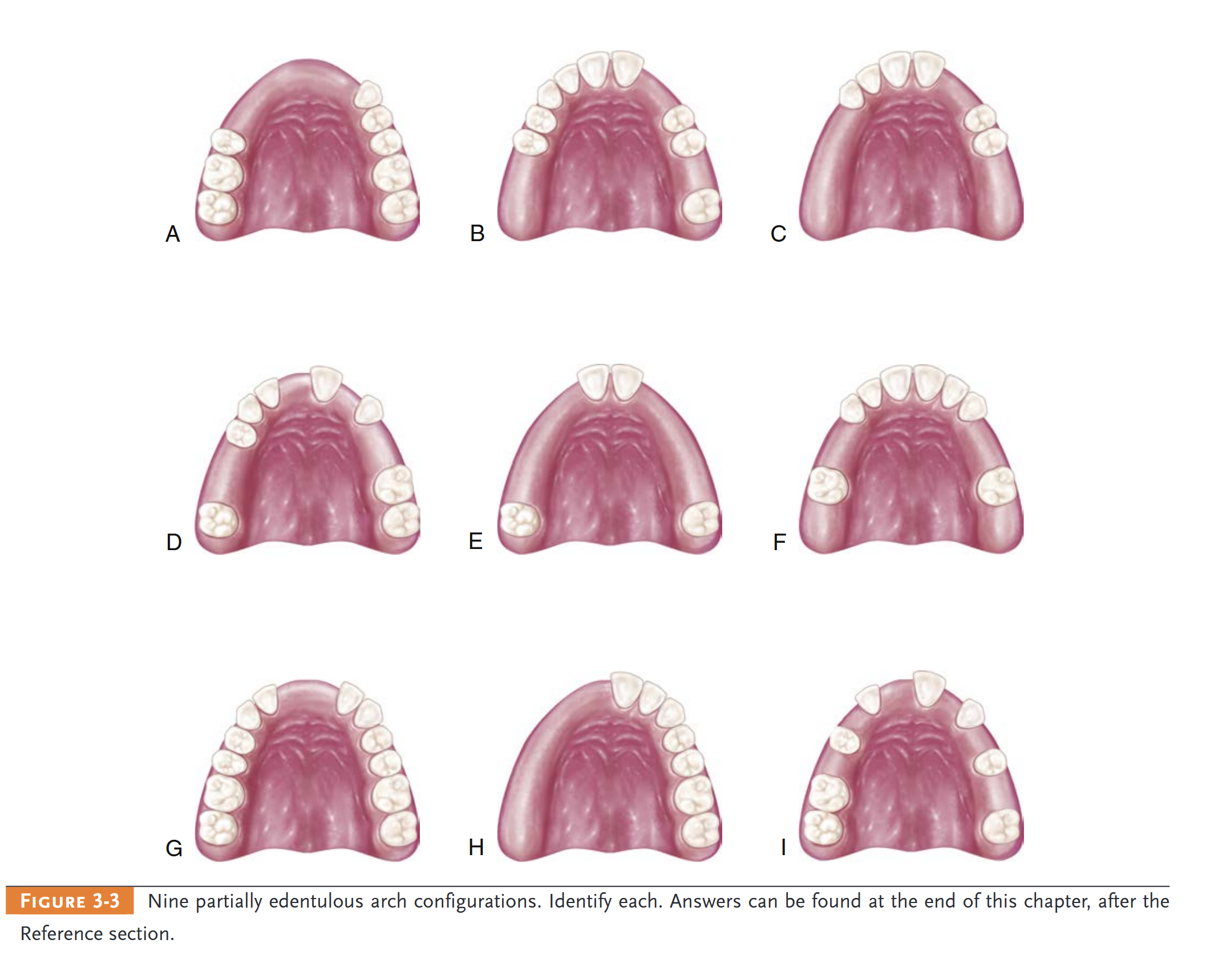
- p. 19: If a second molar is missing and is not to be replaced, it is not considered in the classification (e.g., if the opposing second molar is likewise missing and is not to be replaced).
- p. 19:
- p. 19: Annotation
- p. 19: Annotation
- p. 19: Annotation
- p. 19: Annotation
- p. 19: Annotation
- p. 19: Annotation
- p. 19: Annotation
- p. 19: Annotation
- p. 19: Annotation
- p. 19: Annotation
- p. 19: Annotation
- p. 19: Annotation
- p. 19: Annotation
Other annotations
- p. 16: Classification of Partially Edentulous Arches
- p. 16: Complexity is determined from four broad diagnostic categories that include location and extent of the edentulous areas, condition of the abutments, occlusal characteristics and requirements, and residual ridge characteristic
- p. 16: The Kennedy method is probably the most widely accepted classification of partially edentulous arches.
4 - Biomechanics of Removable Partial Dentures
- Related chapter: 06 4 - Biomechanics of Removable Partial Dentures
BIOMECHANICS AND DESIGN SOLUTIONS
- p. 21: The consequence of prosthesis movement under load is an application of stress to the teeth and tissue that are contacting the prosthesis
BIOMECHANICAL CONSIDERATIONS
- p. 22: Just how this is accomplished in a logical manner may not be clear to a clinician who is new to this exercise.
- p. 22: Designing a removable partial denture can be considered similar to the classic, multifaceted design problem in conventional engineering, which is characterized by being open ended and ill structured. Open ended means that problems typically have more than one solution, and ill structured means that solutions are not the result of standard mathematical formulas used in some structured manner.
- p. 22: The rationale for design should logically develop from analysis of the unique oral condition of each mouth under consideration. However, it is possible that alternative design “solutions” could be applied, and it is the evaluation of perceived merits of these various designs that seems most confusing to clinicians.
- p. 22: The
- p. 22: BIOMECHANICAL CONSIDERATIONS
- p. 22: Whether the supporting structures are capable of resisting the applied forces depends on (1) what typical forces require resistance, (2) what duration and intensity these forces have, (3) what capacity the teeth, implant(s) and/or mucosae have to resist these forces, (4) how material use and application influence this teeth-tissue resistance, and (5) whether resistance changes over time.
- p. 22: it is bone that provides the support for a removable prosthesis
- p. 22: Unquestionably the design of removable partial dentures necessitates mechanical and biological considerations
- p. 22: IMPACT OF IMPLANTS ON MOVEMENTS OF PARTIAL DENTURES
- p. 22: the major functional demand is imposed by chewing, and therefore the greatest benefit of implant use involves resisting instability by improving support. Minimizing rotation about an axis in a Kennedy Class I or II arch, or any long modification span, is important to consider.
- p. 22: Box 4-1
- p. 22: DESIGN PROCESS FOR REMOVABLE PARTIAL DENTURES
SIMPLE MACHINES
- p. 23: Of the simple machines, the lever, the wedge, and the inclined plane should be avoided in the design of removable partial dentures.
- p. 23: It rotates in relation to the three cranial planes because of differences in the support characteristics of the abutment teeth and the soft tissue covering the residual ridge.
- p. 23: Even though the actual movement of the denture may be small, a lever force may be imposed on abutment teeth
- p. 23: Three types of levers are used: first, second, and third class (see Figure 4-2). The potential of a lever system to magnify a force is illustrated in
- p. 23: A cantilever is a beam supported at one end that can act as a first-class lever (Figure 4-5).
- p. 23: A cantilever design should be avoided (Figure 4-6). Use of a dental implant is one strategy to provide tooth replacement and avoid the cantilever. E
- p. 23: The most efficient means of addressing the potential effects of a lever is to provide a rigid element at the unsupported end to disallow movement
- p. 23: Again, a distal extension removable partial denture rotates when forces are applied to the artificial teeth attached to the extension base. Because it can be assumed that this rotation must create predominantly nonvertical forces, the location of
POSSIBLE MOVEMENTS OF PARTIAL DENTURES
- p. 24: stabilizing and retentive components in relation to the horizontal axis of rotation of the abutment becomes extremely importan
- p. 24: An abutment tooth will better tolerate nonvertical forces if these forces are applied as near as possible to the horizontal axis of rotation of the abutment
- p. 24: POSSIBLE MOVEMENTS OF PARTIAL DENTURES
- p. 24: rotational movement will occur about some axis as the distal extension base or bases move toward, away, or horizontally across the underlying tissue
- p. 24: The greatest movement possible is found in the tooth/mucosal tissue–supported prosthesis because of reliance on the distal extension supporting tissue to share the functional loads with the teeth.
- p. 24: Movement of a distal extension base toward the ridge tissue will be proportionate to the quality of that tissue, the accuracy and extent of the denture base, and the applied total functional load
- p. 24: One movement is rotation about an axis through the most posterior abutments.
- p. 24: This axis may pass through occlusal rests or any other rigid portion of a direct retainer assembly located occlusally or incisally to the height of contour of the primary abutments (
- p. 24: This axis, known as the fulcrum line, is the center of rotation as the distal extension base moves toward the supporting tissue when an occlusal load is applied
- p. 28: Clasps placed closer to the occlusal/incisal surface have a greater likelihood of imparting tipping forces to the abutments.
5 - Major and Minor Connectors
- Related chapter: 07 5 - Major and Minor Connectors
ROLE OF MAJOR CONNECTORS IN CONTROL OF PROSTHESIS MOVEMENT > Location
- p. 30: A major connector is the component of the partial denture that connects the parts of the prosthesis located on one side of the arch with those on the opposite side
- p. 30: Major connectors should be designed and located with the following guidelines in mind: 1. Major connectors should be free of movable tissue. 2. Impingement of gingival tissue should be avoided. 3. Bony and soft tissue prominences should be avoided during placement and removal.
- p. 30:

- p. 31: 4. Relief should be provided beneath a major connector to prevent its settling into areas of possible interference, such as inoperable tori or elevated median palatal sutures. 5. Major connectors should be located and/or relieved to prevent impingement of tissue that occurs because the distal extension denture rotates in function.
- p. 31: ppropriate relief beneath the major connector avoids the need for its adjustment after tissue damage has occurr
- p. 31: To accomplish this, it is recommended that the superior border of a lingual bar connector be located a minimum of 4 mm below the gingival margin(s)
- p. 31: Because the connector must have sufficient width and bulk to provide rigidity, a linguoplate is commonly used when space is insufficient for a lingual bar.
- p. 31: tructurally, the tissue covering the palate is well suited for placement of the connector because of the presence of firm submucosal connective tissue and an adequate, deep blood supply
- p. 31: The amount of relief required is directly proportional to the difference in displaceability of the tissue covering the midline of the palate and the tissue covering the residual ridges.
ROLE OF MAJOR CONNECTORS IN CONTROL OF PROSTHESIS MOVEMENT > Mandibular Major Connectors > Lingual Bar
- p. 32: the palatal connector be placed a minimum of 6 mm away from and parallel to the gingival margins.
- p. 32: There are six types of mandibular major connectors described historically. Of these, the lingual bar and the linguoplate are used the majority of the time. 1. Lingual bar (Figure 5-4, A) 2. Linguoplate (see Figure 5-4, B) 3. Sublingual bar (see Figure 5-4, C) 4. Lingual bar with cingulum bar (continuous bar) (see Figure 5-4, D) 5. Cingulum bar (continuous bar) (see Figure 5-4, E) 6. Labial bar (see Figure 5-4, F)
- p. 32: Lingual Bar
- p. 32: The major connector must be contoured so that it does not present sharp margins to the tongue and cause irritation or annoyance by an angular form.
- p. 32: CHARACTERISTICS OF MAJOR CONNECTORS CONTRIBUTING TO HEALTH AND WELL-BEIN
- p. 32: 1. Are made from an alloy compatible with oral tissue 2. Are rigid and provide cross-arch stability through the principle of broad distribution of stress 3. Do not interfere with and are not irritating to the tongue 4. Do not substantially alter the natural contour of the lingual surface of the mandibular alveolar ridge or of the palatal vault 5. Do not impinge on oral tissue when the restoration is placed, is removed, or rotates in function 6. Cover no more tissue than is absolutely necessary 7. Do not contribute to retention or trapping of food particles 8. Have support from other elements of the framework to minimize rotation tendencies in function 9. Contribute to the support of the prosthesis
- p. 33: At least two clinically acceptable methods may be used to determine the relative height of the floor of the mouth and locate the inferior border of a lingual mandibular major connector.
- p. 33: The first method is to measure the height of the floor of
- p. 33:

- p. 33: Mandibular major connectors. A, Lingual bar. B, Linguoplate. C, Sublingual bar. D, Lingual bar with continuous bar (cingulum bar). E, Cingulum bar. F, Labial bar.
ROLE OF MAJOR CONNECTORS IN CONTROL OF PROSTHESIS MOVEMENT > Mandibular Major Connectors > Linguoplate
- p. 34: the mouth in relation to the lingual gingival margins of adjacent teeth with a periodontal probe
- p. 34: The second method is to use an individualized impression tray for which lingual borders are 3 mm short of the elevated floor of the mouth, and then to use an impression material that will permit the impression to be accurately molded as the patient licks the lips.
- p. 34: Linguoplate
- p. 34: f the rectangular space is bounded by the lingual bar, the anterior tooth contacts, and the cingula, and the bordering minor connectors are filled in, a linguoplate results
- p. 35: A linguoplate should be made as thin as is technically feasible and should be contoured to follow the contours of the teeth and the embrasures (Figure 5-8)
- p. 35: The patient should be aware of as little added bulk and as few altered contours as possible
- p. 35: Indications for the use of a linguoplate may be listed as follows:
- p. 35: 1. When the lingual frenum is high or the space available for a lingual bar is limited:
- p. 35: In Class I situations in which the residual ridges have undergone excessive vertical resorption:
- p. 35: For stabilizing periodontally weakened teeth, splinting with a linguoplate can be of some value when used with definite rests on sound adjacent teeth:
- p. 35: When the future replacement of one or more incisor teeth will be facilitated by the addition of retention loops to an existing linguoplate:
- p. 35: Generally, the apron is used to avoid gingival irritation or entrapment of food debris or to cover generously relieved areas that would be irritating to the tongue
ROLE OF MAJOR CONNECTORS IN CONTROL OF PROSTHESIS MOVEMENT > Mandibular Major Connectors > Design of Mandibular Major Connectors
- p. 36: Design of Mandibular Major Connector
- p. 36: Step 1: Outline the basal seat areas on the diagnostic cast
- p. 36: Step 2: Outline the inferior border of the major connector
- p. 36: Step 3: Outline the superior border of the major connector
- p. 36: Step 4: Connect the basal seat area to the inferior and superior borders of the major connector, and add minor connectors to retain the acrylic resin denture base material
- p. 36: Sublingual Bar A modification of the lingual bar that has been demonstrated to be useful when the height of the floor of the mouth does not allow placement of the superior border of the bar at least 4 mm below the free gingival margin is the sublingual bar. The bar shape remains essentially the same as that of a lingual bar, but placement is inferior and posterior to the usual placement of a lingual bar, lying over and parallel to the anterior floor of the mouth. It is generally accepted that a sublingual bar can be used in lieu of a lingual plate if the lingual frenum does not interfere, or in the presence of an anterior lingual undercut that would require considerable blockout for a conventional lingual bar. Contraindications include interfering lingual tori, high attachment of a lingual frenum, and interference with elevation of the floor of the mouth during functional movements. Cingulum Bar (Continuous Bar) When a linguoplate is the major connector of choice but the axial alignment of the anterior teeth is such that excessive blockout of interproximal undercuts must be made, a cingulum bar may be considered. A cingulum bar located on or slightly above the cingula of the anterior teeth may be added to the lingual bar or can be used independently (Figure 5-13). In addition, when wide diastemata exist between the lower anterior teeth, a continuous bar retainer may be more esthetically acceptable than a linguoplate. Labial Bar Fortunately, in only a few situations does extreme lingual inclination of the remaining lower premolar and incisor teeth prevent the use of a lingual bar major connector. With the use of conservative mouth preparations in the form of recontouring and blockout, a lingual major connector can almost always be used. Lingually inclined teeth sometimes may have to be reshaped by means of crowns. Although the use of a labial major connector may be necessary in rare instances, this should be avoided by resorting to necessary mouth preparations rather than by accepting a condition that is otherwise correctable (Figure 5-14). The same applies to the use of a labial bar when a mandibular torus interferes with placement of a lingual bar. Unless surgery is definitely contraindicated, interfering mandibular tori should be removed so that the use of a labial bar connector may be avoided. A modification to the linguoplate is the hinged continuous labial bar. This concept is incorporated in the
ROLE OF MAJOR CONNECTORS IN CONTROL OF PROSTHESIS MOVEMENT > Maxillary Major Connectors
- p. 39: Six basic types of maxillary major connectors are considered: 1. Single palatal strap (Figure 5-17, A) 2. Combination anterior and posterior palatal strap–type connector (see Figure 5-17, B) 3. Palatal plate-type connector (see Figure 5-17, C) 4. U-shaped palatal connector (see Figure 5-17, D) 5. Single palatal bar (see Figure 5-17, E) 6. Anterior-posterior palatal bars (see Figure 5-17, F)
ROLE OF MAJOR CONNECTORS IN CONTROL OF PROSTHESIS MOVEMENT > Maxillary Major Connectors > Single Palatal Strap
- p. 40: Single Palatal Strap
- p. 40: Bilateral tooth-supported prostheses, even those with short edentulous spaces, are effectively connected with a single, broad palatal strap connector, particularly when the edentulous areas are located posteriorly
- p. 40: For reasons of torque and leverage, a single palatal strap major connector should not be used to connect anterior replacements with distal extension bases.
ROLE OF MAJOR CONNECTORS IN CONTROL OF PROSTHESIS MOVEMENT > Maxillary Major Connectors > Design of Maxillary Major Connectors
- p. 42: Design of Maxillary Major Connectors
- p. 42: Step 1: Outline of primary bearing areas: The primary bearing areas are those that will be covered by the denture base(s)
- p. 43: Step 2: Outline of nonbearing areas: The nonbearing areas are the lingual gingival tissue within 5 to 6 mm of the remaining teeth, hard areas of the medial palatal raphe (including tori), and palatal tissue posterior to the vibrating line (see Figure 5-24, C)
- p. 43: Step 3: Outline of connector areas: Steps 1 and 2, when completed, provide an outline or designate areas that are available to plac
- p. 43: Step 4: Selection of connector type: Selection of the type of connector(s) is based on four factors: (1) mouth comfort, (2) rigidity, (3) location of denture bases, and (4) indirect retention. Connectors should be of minimum bulk and should be positioned so that interference with the tongue during speech and mastication is not encountered. Connectors must have a maximum of rigidity to distribute stress bilaterally. The doublestrap type of major connector provides the maximum rigidity without bulk and total tissue coverage. In many
- p. 43: instances, the choice of a strap type of major connector is limited by the location of the edentulous ridge areas. When edentulous areas are located anteriorly, the use of only a posterior strap is not recommended. By the same token, when only posterior edentulous areas are present, the use of only an anterior strap is not recommended. The need for indirect retention influences the outline of the major connector. Provision must be made in the major connector so that indirect retainers may be attached.
- p. 43: Step 5: Unification: After selection of the type of major connector based on considerations in Step 4, the denture base areas and connectors are joined (see Figure 5-24, D).
ROLE OF MAJOR CONNECTORS IN CONTROL OF PROSTHESIS MOVEMENT > Maxillary Major Connectors > U-Shaped Palatal Connector
- p. 44: U-shaped palatal connector is probably the least rigid type of maxillary major connector and should be used only when a large inoperable palatal torus prevents the use of palatal coverage or combination anterior-posterior palatal strap–type designed framework.
ROLE OF MAJOR CONNECTORS IN CONTROL OF PROSTHESIS MOVEMENT > Maxillary Major Connectors > Beading of the Maxillary Cast
- p. 45: MINOR CONNECTORS
- p. 45: Functions
- p. 45: ransfers functional stress to the abutment teeth: This is a prosthesis-to-abutment function of the minor connector.
MINOR CONNECTORS > Form and Location
- p. 46: Transfers the effects of the retainers, rests, and stabilizing components throughout the prosthesis:
- p. 46: A minor connector that contacts the axial surface of an abutment should not be located on a convex surface. Instead it should be located in an embrasure (Figure 5-33), where it will be least noticeable to the tongue.
- p. 46: It should conform to the interdental embrasure, passing vertically from the major connector so that the gingival crossing is abrupt and covers as little of the gingival tissue as possible. It should be thickest toward the lingual surface, tapering toward the contact area
- p. 47: It is a minor connector that contacts the guiding plane surfaces of the abutment teeth, whether as a connected part of a direct retainer assembly or as a separate entity
- p. 48: Ideally the artificial tooth should contact the abutment tooth with only a thin layer of metal intervening buccally.
- p. 48: xtension of the finishing line to the area of the pterygomaxillary notch provides a butt-type joint for attachment of the border portion of the resin base through the pterygomaxillary notch (a
MINOR CONNECTORS > Tissue Stops
- p. 49:

- p. 49: Minor connectors for maxillary distal extension denture bases should extend the entire length of the residual ridge and should be of a ladderlike and loop design
- p. 49: Tissue Stops
Major Connectors in Review
- p. 52: MAJOR CONNECTORS IN REVIEW
- p. 52: unction of the major connector and the minor connector at palatal finishing lines should be located 2 mm medial from an imaginary line that would contact the lingual surfaces of missing posterior teeth. The finish line on the right is too far toward midline of the palate. The natural contours of the palate will be altered.
- p. 52: Mandibular Lingual Bar Indications for Use: The lingual bar should be used for mandibular removable partial dentures when sufficient space exists between the slightly elevated alveolar lingual sulcus and the lingual gingival tissue. Characteristics and Location: (1) Half-pear shaped with bulkiest portion inferiorly located. (2) Superior border tapered to soft tissue. (3) Superior border located at least 4 mm inferior to gingival margins and farther if possible. (4) Inferior border located at the ascertained height of the alveolar lingual sulcus when the patient’s tongue is slightly elevated. Blockout and Relief of Master Cast: (1) All tissue undercuts parallel to the path of placement. (2) An additional Correct Incorrect Figure 5-42 Junction of the major connector and the minor connector at palatal finishing lines should be located 2 mm medial from an imaginary line that would contact the lingual surfaces of missing posterior teeth. The finish line on the right is too far toward midline of the palate. The natural contours of the palate will be altered. thickness of 32-gauge sheet wax when the lingual surface of the alveolar ridge is undercut or parallel to the path of placement (see Figures 11-23 and 11-24). (3) No relief is necessary when the lingual surface of the alveolar ridge slopes inferiorly and posteriorly. (4) One thickness of baseplate wax over basal seat areas (to elevate minor connectors for attaching acrylic-resin denture bases). Waxing Specifications: (1) Six-gauge, half-pear–shaped wax form reinforced by 22- to 24-gauge sheet wax or similar plastic pattern adapted to the design width. (2) Long bar requires more bulk than short bar; however, cross-sectional shape is unchanged. Finishing Lines: Butt-type joint(s) with minor connector(s) for retention of denture base(s). Mandibular Linguoplate Indications for Use: (1) When the alveolar lingual sulcus so closely approximates the lingual gingival crevices that adequate width for a rigid lingual bar does not exist. (2) In those instances in which the residual ridges in Class I arch have undergone such vertical resorption that they will offer only minimal resistance to horizontal rotations of the denture through its bases. (3) For using periodontally weakened teeth in group function to furnish support to the prosthesis and to help resist horizontal (off-vertical) rotation of the distal extension type of denture. (4) When the future replacement of one or more incisor teeth will be facilitated by the addition of retention loops to an existing linguoplate. Characteristics and Location: (1) Half-pear shaped with bulkiest portion inferiorly located. (2) Thin metal apron extending superiorly to contact cingula of anterior teeth and lingual surfaces of involved posterior teeth at their height of contour. (3) Apron extended interproximally to the height of contact points (i.e., closing interproximal spaces). (4) Scalloped contour of apron as dictated by interproximal blockout. (5) Superior border finished to continuous plane with contacted teeth. (6) Inferior border at the ascertained height of the alveolar lingual sulcus when the patient’s tongue is slightly elevated. Blockout and Relief of Master Cast: (1) All involved undercuts of contacted teeth parallel to the path of placement. (2) All involved gingival crevices. (3) Lingual surfaces of alveolar ridge and basal seat areas the same as for a lingual bar. Waxing Specifications: (1) Inferior border: 6-gauge, halfpear–shaped wax form reinforced with 24-gauge sheet wax or similar plastic pattern. (2) Apron: 24-gauge sheet wax. Finishing Lines: Butt-type joint(s) with minor connector(s) for retention of denture base(s). Mandibular Sublingual Bar Indications for Use: The sublingual bar should be used for mandibular removable partial dentures when the height of the floor of the mouth in relation to the free gingival margins will be less than 6 mm. It also may be indicated whenever it is desirable to keep the free gingival margins of the Chapter 5 Major and Minor Connectors 53 remaining anterior teeth exposed and depth of the floor of the mouth is inadequate to place a lingual bar. Contraindications for Use: Remaining natural anterior teeth severely tilted toward the lingual. Characteristics and Location: The sublingual bar is essentially the same half-pear shape as a lingual bar, except that the bulkiest portion is located to the lingual and the tapered portion is toward the labial. The superior border of the bar should be at least 3 mm from the free gingival margin of the teeth. The inferior border is located at the height of the alveolar lingual sulcus when the patient’s tongue is slightly elevated. This necessitates a functional impression of the lingual vestibule to accurately register the height of the vestibule. Blockout and Relief of Master Cast: (1) All tissue undercuts parallel to path of placement. (2) An additional thickness of 32-gauge sheet wax when the lingual surface of the alveolar ridge is undercut or parallel to the path of placement. (3) One thickness of baseplate wax over basal seat areas (to elevate minor connectors for attaching acrylic-resin denture bases). Waxing Specifications: (1) Six-gauge, half-pear–shaped wax form reinforced by 22- to 24-gauge sheet wax or similar plastic pattern adapted to design width. (2) Long bar bulkier than short bar; however, cross-sectional shape unchanged. Finishing Lines: Butt-type joint(s) with minor connector(s) for retention of denture base(s). Mandibular Lingual Bar with Continuous Bar (Cingulum Bar) Indications for Use: (1) When a linguoplate is otherwise indicated but the axial alignment of anterior teeth is such that excessive blockout of interproximal undercuts would be required. (2) When wide diastemata exist between mandibular anterior teeth and a linguoplate would objectionably display metal in a frontal view. Characteristics and Location: (1) Conventionally shaped and located same as lingual bar major connector component when possible. (2) Thin, narrow (3 mm) metal strap located on cingula of anterior teeth, scalloped to follow interproximal embrasures with inferior and superior borders tapered to tooth surfaces. (3) Originates bilaterally from incisal, lingual, or occlusal rests of adjacent principal abutments. Blockout and Relief of Master Cast: (1) Lingual surfaces of alveolar ridge and basal seat areas same as for lingual bar. (2) No relief for continuous bar except blockout of interproximal spaces parallel to path of placement. Waxing Specifications: (1) Lingual bar major connector component waxed and shaped same as lingual bar. (2) Continuous bar pattern formed by adapting two strips (3 mm wide) of 28-gauge sheet wax, one at a time, over the cingula and into interproximal embrasures. Finishing Lines: Butt-type joint(s) with minor connector(s) for retention of denture base(s). Mandibular Continuous Bar (Cingulum Bar) Indications for Use: When a lingual plate or sublingual bar is otherwise indicated but the axial alignment of the anterior teeth is such that excessive blockout of interproximal undercuts would be required. Contraindications for Use: (1) Anterior teeth severely tilted to the lingual. (2) When wide diastemata that exist between the mandibular anterior teeth and the cingulum bar would objectionably display metal in a frontal view. Characteristics and Location: (1) Thin, narrow (3 mm) metal strap located on cingula of anterior teeth, scalloped to f
- p. 54: components by a labial or buccal approach. (4) Minor connectors for base attachment joined by a labial or buccal approach. Finishing Lines: Butt-type joint(s) with minor connector(s) for retention of denture base(s). Single Palatal Strap–Type Major Connector Indications for Use: Bilateral edentulous spaces of short span in a tooth-supported restoration. Characteristics and Location: (1) Anatomic replica form. (2) Anterior border follows the valleys between rugae as nearly as possible at right angles to median suture line. (3) Posterior border at right angle to median suture line. (4) Strap should be 8 mm wide or approximately as wide as the combined width of a maxillary premolar and first molar. (5) Confined within an area bounded by the four principal rests. Blockout and Relief of Master Cast: (1) Usually none required except slight relief of elevated medial palatal raphe or any exostosis crossed by the connector. (2) One thickness of baseplate wax over basal seat areas (to elevate minor connectors for attaching acrylic-resin denture bases). Beading: See Figures 5-38 to 5-41. Waxing Specifications: Anatomic replica pattern equivalent to 22- to 24-gauge wax, depending on arch width. Finishing Lines: (1) Undercut and slightly elevated. (2) No farther than 2 mm medial from an imaginary line contacting lingual surfaces of principal abutments and teeth to be replaced. (3) Follow curvature of arch. Single Broad Palatal Major Connector Indications for Use: (1) Class I partially edentulous arches with residual ridges that have undergone little vertical resorption and will lend excellent support. (2) V- or U-shaped palates. (3) Strong abutments (single or made so by splinting). (4) More teeth in arch than six remaining anterior teeth. (5) Direct retention not a problem. (6) No interfering tori. Characteristics and Location: (1) Anatomic replica form. (2) Anterior border following valleys of rugae as near right angle to median suture line as possible and not extending anterior to occlusal rests or indirect retainers. (3) Posterior border located at junction of hard and soft palate but not extended onto soft palate; at right angle to the median suture line; extended to pterygomaxillary notches. Blockout and Relief of Master Cast: (1) Usually none required except relief of elevated median palatal raphe or any small exostoses covered by the connector. (2) One thickness of baseplate wax over basal seat areas (to elevate minor connectors for attaching acrylic-resin denture bases). Beading: See Figures 5-28 to 5-30. Waxing Specifications: Anatomic replica pattern equivalent to 24-gauge sheet wax thickness. Finishing Lines: (1) Provision for butt-type joint at pterygomaxillary notches. (2) Undercut and slightly elevated. (3) No farther than 2 mm medial from an imaginary line contacting the lingual surfaces of the missing natural teeth. (4) Following curvature of arch. Anterior-Posterior Strap–Type Major Connector Indications for Use: (1) Class I and II arches in which excellent abutment and residual ridge support exists, and direct retention can be made adequate without the need for indirect retention. (2) Long edentulous spans in Class II, modification 1 arches. (3) Class IV arches in which anterior teeth must be replaced with a removable partial denture. (4) Inoperable palatal tori that do not extend posteriorly to the junction of the hard and soft palates. Characteristics and Location: (1) Parallelogram shaped and open in center portion. (2) Relatively broad (8 to 10 mm) anterior and posterior palatal straps. (3) Lateral palatal straps (7 to 9 mm) narrow and parallel to curve of arch; minimum of 6 mm from gingival crevices of remaining teeth. (4) Anterior palatal strap: Anterior border not placed farther anteriorly than anterior rests and never closer than 6 mm to lingual gingival crevices; follows the valleys of the rugae at right angles to the median palatal suture. Posterior border, if in rugae area, follows valleys of rugae at right angles to the median palatal suture. (5) Posterior palatal connector: Posterior border located at junction of hard and soft palates and at right angles to median palatal suture and extended to hamular notch area(s) on distal extension side(s). (6) Anatomic replica or matte surface. Blockout and Relief of Master Cast: (1) Usually none required except slight relief of elevated median palatal raphe where anterior or posterior straps cross the palate. (2) One thickness of baseplate wax over basal seat areas (to elevate minor connectors for attaching acrylic-resin denture bases). Beading: See Figures 5-28 and 5-29. Waxing Specifications: (1) Anatomic replica patterns or matte surface forms of 22-gauge thickness. (2) Posterior palatal component: A strap of 22-gauge thickness, 8 to 10 mm wide (a half-oval form of approximately 6-gauge thickness and width) may also be used. Finishing Lines: Same as for single broad palatal major connector. Complete Palatal Coverage Major Connector Indications for Use: (1) In most situations in which only some or all anterior teeth remain. (2) Class II arch with a large posterior modification space and some missing anterior teeth. (3) Class I arch with one to four premolars and some or all anterior teeth remaining, when abutment support is poor and cannot otherwise be enhanced; residual ridges have undergone extreme vertical resorption; direct retention is difficult to obtain. (4) In the absence of a pedunculated torus. Characteristics and Location: (1) Anatomic replica form for full palatal metal casting supported anteriorly by positive Chapter 5 Major and Minor Connectors 55 rest seats. (2) Palatal linguoplate supported anteriorly and designed for attachment of acrylic-resin extension posteriorly. (3) Contacts all or almost all of the teeth remaining in the arch. (4) Posterior border: Terminates at the junction of the hard and soft palates; extended to hamular notch area(s) on distal extension side(s); at a right angle to median suture line. Blockout and Relief of Master Cast: (1) Usually none required except relief of elevated median palatal raphe or any small palatal exostosis. (2) One thickness of baseplate wax over basal seat areas (to elevate minor connectors for attaching acrylic-resin denture bases). Beading: See Figures 5-28 to 5-30. Waxing Specifications: (1) Anatomic replica pattern equivalent to 22- to 24-gauge sheet wax thickness. (2) Acrylic-resin extension from linguoplate the same as for a complete denture. Finishing Lines: As illustrated here and previously discussed. U-Shaped Palatal Major Connector This connector should be used only in those situations in which inoperable tori extend to the posterior limit of the hard palate. The U-shaped palatal major connector is the least favorable design of all palatal major connectors because it lacks the rigidity of other types of connectors. When it must be used, indirect retainers must support any portion of the connector that extends anteriorly from the principal occlusal rests. Anterior border areas of this type of connector must be kept at least 6 mm away from adjacent teeth. If for any reason the anterior border must contact the remaining teeth, the connector must again be supported by rests placed in properly prepared rest seats. It should never be supported even temporarily by inclined lingual surfaces of anterior teeth. Waxing specifications, finishing lines, and so forth, are the same as for full palatal castings o
Other annotations
- p. 29: at is the role of the major connector. Components of a typical removable partial denture are illustrated in Figure 5-1. 1. Major connectors 2. Minor connectors 3. Rests 4. Direct retainers 5. Stabilizing or reciprocal components (as parts of a clasp assembly) 6. Indirect retainers (if the prosthesis has distal extension bases) 7. One or more bases, each supporting one to several replacement teeth (see Figure 5-1)
- p. 29: The chief functions of a major connector include unification of the major parts of the prosthesis, distribution of the applied force throughout the arch to selected teeth and tissue, and minimization of torque to individual teeth.
- p. 29: The principle of leverage is connected with this component part. A rigid major connector limits movement possibilities by acting as a counteracting lever. This phenomenon is referred to as cross-arch stability.
6 - Rests and Rest Seats
- Related chapter: 08 6 - Rests and Rest Seats
ROLE OF RESTS IN CONTROL OF PROSTHESIS MOVEMENT
- p. 56: ROLE OF RESTS IN CONTROL OF PROSTHESIS MOVEMENT
- p. 57: The primary purpose of the rest is to provide vertical support for the partial denture. In doing so, it also does the following: 1. Maintains components in their planned positions 2. Maintains established occlusal relationships by preventing settling of the denture 3. Prevents impingement of soft tissue 4. Directs and distributes occlusal loads to abutment teeth Thus rests serve to support the position of a partial denture and to resist movement toward the tissue.
FORM OF THE OCCLUSAL REST AND REST SEAT
- p. 58: FORM OF THE OCCLUSAL REST AND REST SEAT
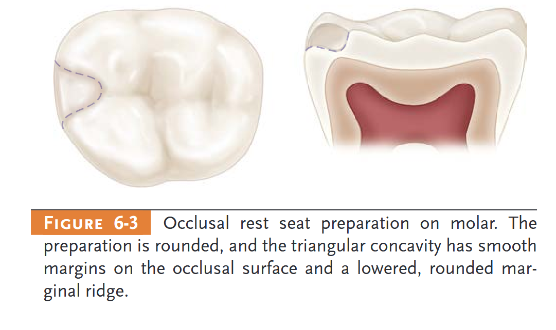
- p. 58: The form of the occlusal rest seat should be designed and located with the following guidelines in mind: 1. The outline form of an occlusal rest seat should be a rounded triangular shape with the apex toward the center of the occlusal surface (Figure 6-2). 2. It should be as long as it is wide, and the base of the triangular shape (at the marginal ridge) should be at least 2.5 mm for both molars and premolars. Rest seats of smaller dimensions do not provide an adequate bulk of metal for rests, especially if the rest is contoured to restore the occlusal morphology of the abutment tooth. 3. The marginal ridge of the abutment tooth at the site of the rest seat must be lowered to permit a sufficient bulk of metal for strength and rigidity of the rest and the minor connector. This means that a reduction of the marginal ridge of approximately 1.5 mm is usually necessary. 4. The floor of the occlusal rest seat should be apical to the marginal ridge and the occlusal surface and should be concave, or spoon shaped (Figure 6-3). Caution should be exercised in preparing a rest seat to avoid creating sharp edges or line angles in the preparation.
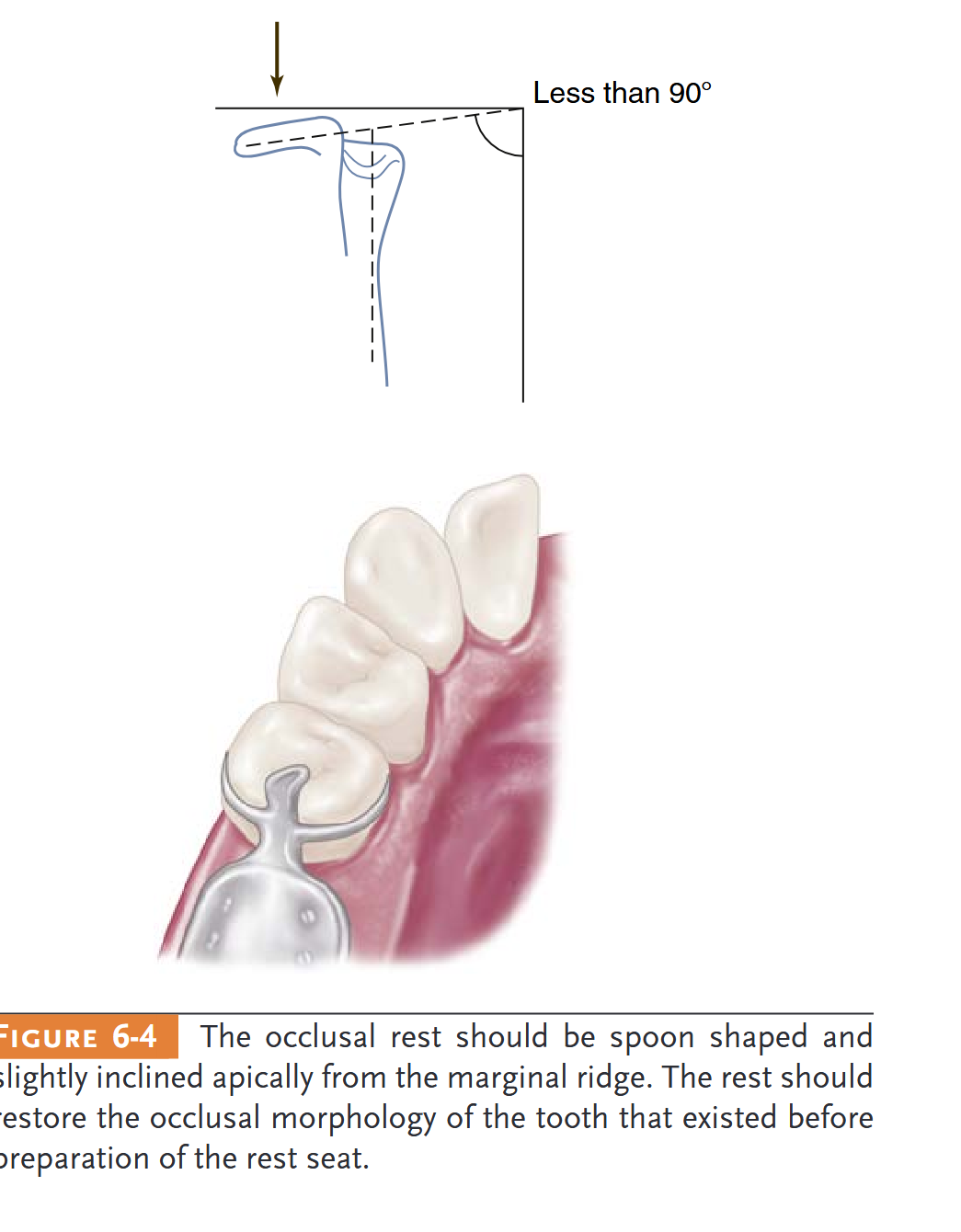
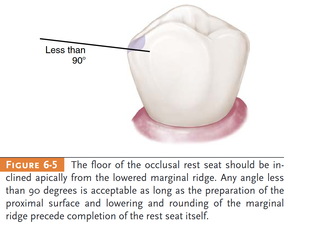
- p. 58: The angle formed by the occlusal rest and the vertical minor connector from which it originates should be less than 90 degrees (Figures 6-4 and 6-5). Only in this way can the occlusal forces be directed along the long axis of the abutment tooth. An angle greater than 90 degrees fails to transmit occlusal forces along the supporting vertical axis of the abutment tooth. This also permits slippage of the prosthesis away from the abutment, which can result in orthodontic-like forces being applied to an inclined plane on the abutment, with possible tooth movement (Figure 6-6).
- p. 58:

- p. 58:
- p. 58:
- p. 58:
EXTENDED OCCLUSAL REST
- p. 59: hen an existing occlusal rest preparation is inclined apically toward the reduced marginal ridge and cannot be modified or deepened because of fear of perforation of the enamel or restoration, then a secondary occlusal rest must be employed to prevent slippage of the primary rest and orthodontic movement of the abutment tooth (Figure 6-7)
- p. 59: n Kennedy Class II, modification 1, and Kennedy Class III situations in which the most posterior abutment is a mesially tipped molar, an extended occlusal rest should be designed and prepared to minimize further tipping of the abutment and to ensure that the forces are directed down the long axis of the abutment.
- p. 59: This rest should extend more than one-half the mesiodistal width of the tooth, should be approximately one-third the buccolingual width of the tooth, and should allow for a minimum of 1-mm thickness of the metal; the preparation should be rounded with no undercuts or sharp angles (
- p. 59: n situations in which the abutment is severely tilted, the extended occlusal rest may take the form of an onlay to restore the occlusal plane (Figure 6-9).
INTERPROXIMAL OCCLUSAL REST SEATS
- p. 60: INTERPROXIMAL OCCLUSAL REST SEATS
- p. 60: The design of a direct retainer assembly may require the use of interproximal occlusal rests (Figure 6-10). These rest seats are prepared as individual occlusal rest seats, with the exception that the preparations must be extended farther lingually than is ordinarily accomplished (Figure 6-11).
INCISAL RESTS AND REST SEATS
- p. 65: Incisal rests are placed at the incisal angles of anterior teeth and on prepared rest seats. Although this is the least desirable placement of a rest seat for reasons previously mentioned, it may be used successfully for selected patients when the abutment is sound and when a cast restoration is not otherwise indicated. Therefore incisal rests generally are placed on enamel (Figure 6-20). Incisal rests are
7 - Direct Retainers
- Related chapter: 09 7 - Direct Retainers
DIRECT RETAINER’S ROLE IN CONTROL OF PROSTHESIS MOVEMENT
- p. 67: n general, the forces acting to move prostheses toward and across the supporting teeth and/or tissue are the greatest in intensity. This is because most often they are forces of occlusion.
- p. 67: The component part applied to resist this movement away from the teeth and/or tissue provides retention for the prosthesis and is called the direct retainer. A direct retainer is any unit of a removable dental prosthesis that engages an abutment tooth or implant to resist displacement of the prosthesis away from basal seat tissue.
BASIC PRINCIPLES OF CLASP DESIGN
- p. 68: Primary retention for the removable partial denture is accomplished mechanically by placing retaining elements (direct retainers) on the abutment teeth. Secondary retention is provided by the intimate relationship of the minor connector contact with the guiding planes and denture bases and of the major connector (maxillary) with underlying tissue. The latter is similar to the retention of a complete denture.
- p. 68: BASIC PRINCIPLES OF CLASP DESIGN
- p. 68: ea, and (3) the reciprocal clasp terminal area. In addition to encirclement, other basic principles of clasp design are as follows: 1. The occlusal rest must be designed to prevent movement of the clasp arms toward the cervical. 2. Each retentive terminal should be opposed by a reciprocal component capable of resisting any transient pressures exerted by the retentive arm during placement and removal. Stabilizing and reciprocal components must be rigidly connected bilaterally (cross-arch) to realize reciprocation of the retentive elements (Figure 7-2). 3. Clasp retainers on abutment teeth adjacent to distal extension bases should be designed so that they avoid direct transmission of tipping and rotational forces to the abutment. In effect, they must act as stress-breakers, either by their design or by their construction. This is accomplished
BASIC PRINCIPLES OF CLASP DESIGN > Reciprocal Arm Functions
- p. 69: hrough proper location of the retentive terminal relative to the rest, or by the use of a more flexible clasp arm in relation to the anticipated rotation of the denture under functional forces. 4. Unless guiding planes will positively control the path of removal and will stabilize abutments against rotational movement, retentive clasps should be bilaterally opposed (i.e., buccal retention on one side of the arch should be opposed by buccal retention on the other, or lingual on one side opposed by lingual on the other). In Class II situations, the third abutment may have buccal or lingual retention. In Class III situations, retention may occur bilaterally or may be diametrically opposed (Figure 7-3). 5. The path of escapement for each retentive clasp terminal must be other than parallel to the path of removal for the prosthesis to require clasp engagement with the resistance to deformation that is retention. 6. The amount of retention should always be the minimum necessary to resist reasonable dislodging forces. 7. Reciprocal elements of the clasp assembly should be located at the junction of the gingival and middle thirds of the crowns of abutment teeth. The terminal end of the retentive arm is optimally placed in the gingival third of the crown (Figures 7-4 through 7-6). These locations permit better resistance to horizontal and torquing forces caused by a reduction in the effort arm as described in Chapte
- p. 69:

TYPES OF DIRECT RETAINERS
- p. 70: Two basic types of direct retainers are available: (1) the intracoronal retainer and (2) the extracoronal retainer. Th
- p. 70: The intracoronal retainer may be cast or may be attached totally within the restored natural contours of an abutment tooth
CRITERIA FOR SELECTING A GIVEN CLASP DESIGN
- p. 71: CRITERIA FOR SELECTING A GIVEN CLASP DESIGN
- p. 71: a direct retainer is simplified. Although some rather complex designs are used for clasp arms, they all may be classified into one of two basic categories. One is the circumferential clasp arm, which approaches the retentive undercut from an occlusal direction. The other is the bar clasp arm, which approaches the retentive undercut from a cervical direction. A clasp assembly may comprise various retentive arms
TYPES OF CLASP ASSEMBLIES > Clasps Designed to Accommodate Functional Movement > RPI, RPA, and Bar Clasp
- p. 72: Clasps Designed to Accommodate Functional Movement
- p. 72: RPI, RPA, and Bar Clasp
- p. 72: the concern of a Class I lever. The concern is that the distal extension acts as a long “effort arm” across the distal rest “fulcrum” to cause the clasp tip “resistance arm” to engage the tooth undercu
- p. 72: The RPI is a current concept of bar clasp design that refers to the rest, proximal plate, and I-bar component parts of the clasp assembly.
- p. 73: Annotation
- p. 73: The
- p. 73: The auxiliary occlusal rest (mirror view) may be used rather than the reciprocal clasp arm without violating any principle of clasp design. Its greatest disadvantages are that the second rest seat must be prepared and that enclosed tissue space at the gingival margin can result in a food trap. The auxiliary occlusal rest is also sometimes used to prevent slippage when the principal occlusal rest seat cannot be inclined apically from the marginal ridge.
- p. 77: When severe tooth and tissue undercuts exist, a bar clasp arm usually is an annoyance to the tongue and cheek and may traps food debris. Other limiting factors in the selection of a bar clasp assembly include a shallow vestibule or an excessive buccal or lingual tilt of the abutment tooth (Figure 7-18).
TYPES OF CLASP ASSEMBLIES > Clasps Designed Without Movement Accommodation > Circumferential Clasp > Ring Clasp
- p. 80: The circumferential clasp is usually the most logical clasp to use with all tooth-supported partial dentures because of its retentive and stabilizing ability (Figure 7-23). Only when the retentive undercut may be approached better with a bar clasp arm or when esthetics will be enhanced should the latter be used.
- p. 80: Ring Clasp
- p. 80: It is used when a proximal undercut cannot be approached by other means. For example, when a mesiolingual undercut on a lower molar abutment cannot be approached directly because of its proximity to the occlusal rest area and cannot be approached with a bar clasp arm because of lingual inclination of the tooth, the ring clasp encircling the tooth allows the undercut to be approached from the distal aspect of the tooth
TYPES OF CLASP ASSEMBLIES > Clasps Designed Without Movement Accommodation > Circumferential Clasp > Embrasure Clasp
- p. 81: In the fabrication of an unmodified Class II or Class III partial denture, no edentulous spaces are available on the opposite side of the arch to aid in clasping.
- p. 81: Embrasure clasps should have two retentive clasp arms and two reciprocal clasp arms that are bilaterally or diagonally opposed
AMOUNT OF RETENTION
AMOUNT OF RETENTION > Size of and Distance into the Angle of Cervical Convergence
- p. 85: Size of and Distance into the Angle of Cervical Convergence
- p. 86: e most suitable path of placement is generally considered to be the path of placement that requires the least amount of mouth preparation necessary to place the components of the partial denture in their ideal position on the tooth surfaces and in relation to the soft tissue. Then mouth preparations are planned with a definite path of placement in mind.
- p. 86: Retention is provided primarily by the flexible portion of the clasp assembly. Retentive terminals are ideally located in measured undercuts in the gingival third of abutment crowns.
- p. 87: Retentive areas are not sufficient to resist reasonable dislodging forces when a cast is surveyed at its most advantageous position (occlusal plane parallel to the surveyor table), even though guide planes could be established with minor tooth modification. B, Tilting cast creates functionally ineffective tooth contours, which are present only in relation to the surveying rod and do not exist when compared with the most advantageous position (position in which restoration will be subject to dislodging forces in an occlusal direction). C and D, Clasps designed at tilt are ineffective without the development of corresponding guide planes to resist displacement when the restoration is subject to dislodging forces in the occlusal direct
8 - Indirect Retainers
- Related chapter: 10 8 - Indirect Retainers
ROLE OF INDIRECT RETAINERS IN CONTROL OF PROSTHESIS MOVEMENT
- p. 93: Annotation
- p. 93: ooth-supported partial dentures effectively use teeth to control movement away from the tissues. Tooth-tissue–supported partial dentures do not have this capability because one end of the prosthesis is free to move away from the tissue.
- p. 93: Theoretically, this movement away from the tissues can be resisted by activation of the direct retainer, the stabilizing components of the clasp assembly, and the rigid components of the partial denture framework, which are located on definite rests on the opposite side of the fulcrum line away from the distal extension base
- p. 93: ndirect retainer components should be placed as far as possible from the distal extension base, which provides the best leverage advantage against dislodgment (
- p. 93: An indirect retainer consists of one or more rests and the supporting minor connectors
- p. 93: The proximal plates, adjacent to the edentulous areas, also provide indirect retention.
FORMS OF INDIRECT RETAINERS > Auxiliary Occlusal Rest
- p. 96: as far from the distal extension base as possible in a prepared rest seat on a tooth capable of supporting its function. Although the most effective location of an indirect retainer is commonly in the vicinity of an incisor tooth, that tooth may not be strong enough to support an indirect retainer and may have steep inclines that cannot be favorably altered to support a rest. In such a situation, the nearest canine tooth or the mesio-occlusal surface of the first premolar may be the best location for the indirect retention, despite the fact that it is not as far removed from the fulcrum line. Whenever possible, two indirect retainers closer to the fulcrum line are used to compensate for the compromise in distance
- p. 96: FACTORS INFLUENCING EFFECTIVENESS OF INDIRECT RETAINERS
- p. 96: 1. The principal occlusal rests on the primary abutment teeth must be reasonably held in their seats by the retentive arms of the direct retainers.
- p. 96: Distance from the fulcrum line. The following three areas must be considered: a. Length of the distal
- p. 96: 3. Rigidity of the connectors supporting the indirect retainer. All connectors must be rigid if the indirect retainer is to function as intended. 4. Effectiveness of the suppor
- p. 96: 4. Effectiveness of the supporting tooth surface. The indirect retainer must be placed on a definite rest seat on which slippage or tooth movement will not occur. Tooth inclines and weak teeth should never be used to support indirect retainers.
- p. 96: It tends to reduce anteroposterior tilting leverages on the principal abutments
- p. 96: It may provide the first visual indications for the need to reline an extension base partial denture. Deficiencies in basal seat support are manifested by the dislodgment of indirect retainers from their prepared rest seats when the denture base is depressed and rotation oc
- p. 96: Annotation
- p. 96: The most commonly used indirect retainer is an auxiliary occlusal rest located on an occlusal surface and as far away from the distal extension base as possibl
FORMS OF INDIRECT RETAINERS > Canine Rests
- p. 97: Indirect retainers for Class II partial dentures are usually placed on the marginal ridge of the first premolar tooth on the opposite side of the arch from the distal extension base (Figure 8-6)
- p. 97: When the mesial marginal ridge of the first premolar is too close to the fulcrum line, or when the teeth are overlapped so that the fulcrum line is not accessible, a rest on the adjacent canine tooth may be used.
10 - Principles of Removable Partial Denture Design
- Related chapter: 12 10 - Principles of Removable Partial Denture Design
DIFFERENTIATION BETWEEN TWO MAIN TYPES OF REMOVABLE PARTIAL DENTURES
- p. 113: The Class I type and the distal extension side of t
- p. 113: the Class II type derive their primary support from tissues underlying the base and secondary support from the abutment teeth
- p. 113: The Class III type derives all of its support from the abutment teeth (see Figure 10-1, B, and Figure 10-2).
- p. 113: tooth-supported, Class III type, no extension base is present to lift away from the supporting tissues because of the action of sticky foods and the movements of tissues of the mouth against the borders of the dentur
- p. 113: Therefore the tooth-supported partial denture does not rotate about a fulcrum, as does the distal extension partial denture
DIFFERENTIATION BETWEEN TWO MAIN TYPES OF REMOVABLE PARTIAL DENTURES > Differences in Support
- p. 114: Because this type of prosthesis does not move under function (other than within the physiologic limitations of tooth support units), the only requirement for such clasps is that they flex sufficiently during placement and removal of the denture to pass over the height of contour of the teeth in approaching or escaping from an undercut area
ESSENTIALS OF PARTIAL DENTURE DESIGN
- p. 115: In the combination tooth- and tissue-supported RPD, because of the anticipated functional movement of the distal extension base, the direct retainer adjacent to the distal extension base must perform still another function, in addition to resisting vertical displacement.
- p. 115: On the other hand, a clasp used in conjunction with a mesial rest may not transmit as much stress to the abutment tooth because of the reduction in leverage forces that results from a change in the fulcrum position. This serves the purpose of reducing or “breaking” the stress, hence the term stress-breakers, and is a strategy that is often incorporated into partial denture designs through various means.
- p. 115: Only the retentive arm of the circumferential clasp, however, should be made of wrought metal
- p. 115: This is called a combination clasp
- p. 115: Annotation
- p. 115: The design of the partial denture framework should be systematically developed and outlined on an accurate diagnostic cast based on the following prosthesis concepts: where the prosthesis is supported, how the support is connected, how the prosthesis is retained, how the retention and support are connected, and how edentulous base support is connected
- p. 115: Annotation
- p. 115: In evaluating the potential support that an abutment tooth can provide, consideration should be given to (1) periodontal health; (2) crown and root morphologies; (3) crown-to-root ratio; (4) bone index area (how tooth has responded to previous stress); (5) location of the tooth in the arch; (6) relationship of the tooth to other support units (length of edentulous span); and (7) the opposing dentition. For a more in-depth understanding of these considerations,
- p. 116: As was stated in Chapter 7, retention is accomplished by placement of mechanical retaining elements (clasps) on the abutment teeth and by the intimate relationship of the denture bases and major connectors (maxillary) with the underlying tissue
- p. 116: (1) avoid direct transmission of tipping or torquing forces to the abutment; (2) accommodate the basic principles of clasp design by definitive location of component parts correctly positioned on abutment tooth surfaces; (3) provide retention against reasonable dislodging forces (with consideration for indirect retention); and (4) be compatible with undercut location, tissue contour, and esthetic desires of the patient.
- p. 116: The fourth step is to connect the retention units to the support units. If direct and indirect retainers are to function as designed, each must be rigidly attached to the major connector
COMPONENTS OF PARTIAL DENTURE DESIGN > Tooth Support
- p. 117: Annotation
- p. 117: In the Kennedy Class III partial denture, three components are necessary: (1) support provided by rests, (2) the connectors (stabilizing components), and (3) the retainers
- p. 117: the support comes from both the teeth and the underlying ridge tissues rather than from the teeth alone
- p. 117: This is often referred to as indirect retention and is best described in relation to an axis of rotation through the rest areas of the principal abutments (see Chapter 8).
- p. 117: alveolar support of those teeth, the crown and root morphology, the rigidity of the partial denture framework, and the design of the occlusal rest
COMPONENTS OF PARTIAL DENTURE DESIGN > Direct Retainers for Distal Extension Partial Dentures
- p. 120: The purpose of all stabilizing components should be to distribute stresses equally to all supporting teeth without overworking any one tooth
- p. 120: All minor connectors that contact vertical tooth surfaces (and all reciprocal clasp arms) act as stabilizing components
- p. 120: A modification of minor connector design has been proposed that places the minor connector in the center of the lingual surface of the abutment tooth
COMPONENTS OF PARTIAL DENTURE DESIGN > Guiding Plane
- p. 121: Guiding planes may be contacted by various components of the partial denture—the body of an extracoronal direct retainer, the stabilizing arm of a direct retainer, the minor connector portion of an indirect retainer—or by a minor connector specifically designed to contact the guiding plane surface. The fu
- p. 121: Establishing guiding planes on several abutment teeth (preferably more than two teeth), located at widely separated positions in the dental arch, provides for more effective use of these surfaces.
- p. 121: As a rule, proximal guiding plane surfaces should be about one-half the width of the distance between the tips of adjacent buccal and lingual cusps, or about one-third the buccal lingual width of the tooth
- p. 121: should extend vertically about two thirds of the length of the enamel crown portion of the tooth from the marginal ridge cervical
- p. 121: An indirect retainer must be placed as far anterior from the fulcrum line as adequate tooth support permits if it is to function with the direct retainer to restrict movement of a distal extension base away from the basal seat tissues.
EXAMPLES OF SYSTEMATIC APPROACH TO DESIGN > Required Tooth Modification for Removable Partial Dentures
- p. 122: the support of an indirect retainer, and the rest seat must be prepared with as much care as is given any other rest se
EXAMPLES OF SYSTEMATIC APPROACH TO DESIGN > Kennedy Class II Removable Partial Dentures
- p. 123: Annotation