Analogue Films and Common Film Faults1
Dr Dayea Oh
OMF Radiologist
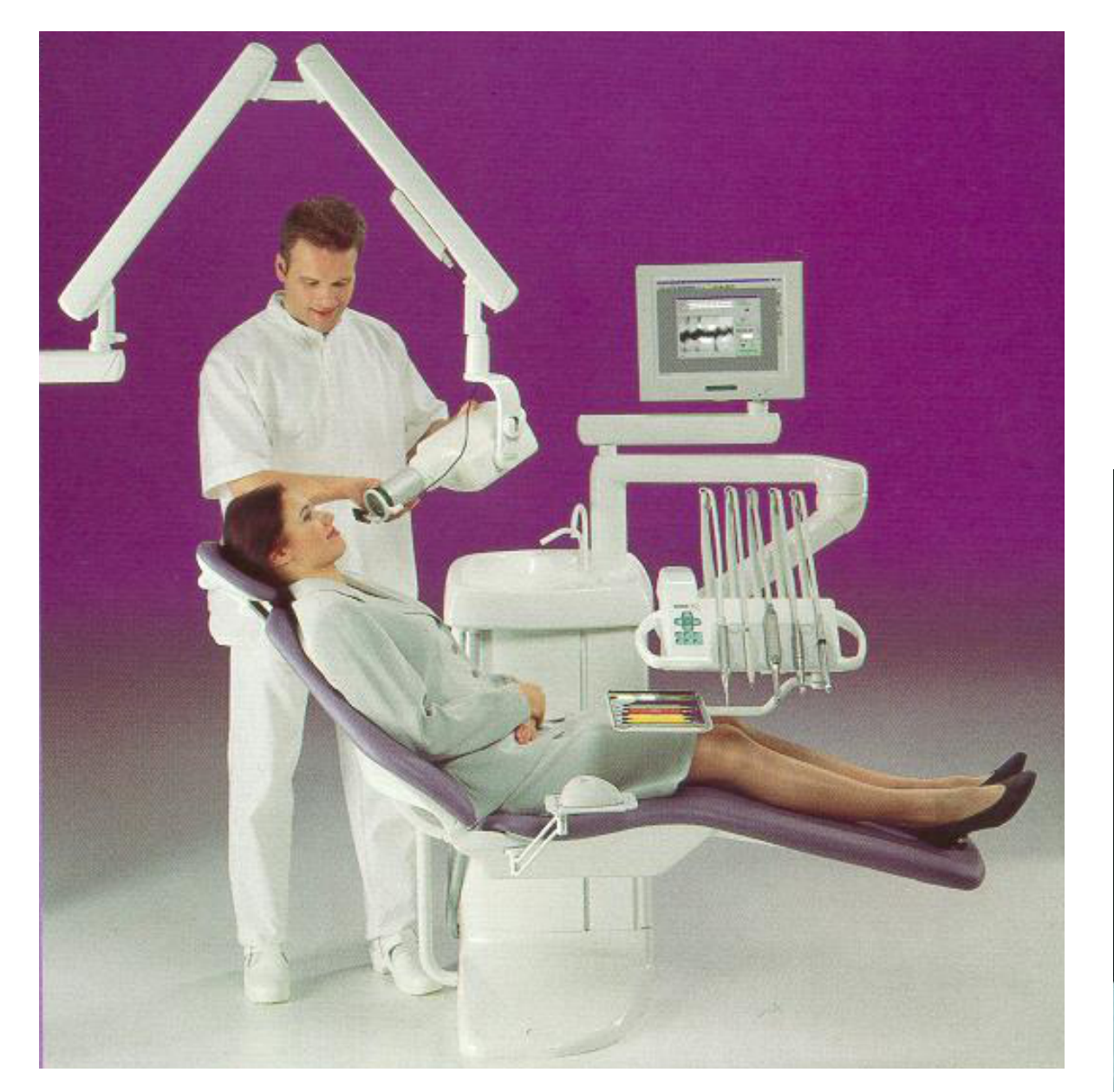
Introduction to Intraoral Radiography23
Review of Intra-oral Radiography
Intra-oral Radiography:
- 2D, diagnostic imaging using ionising radiation (= x-ray beam)
- Clinical workflow:
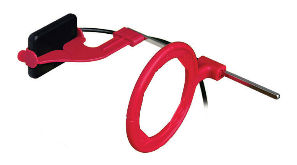
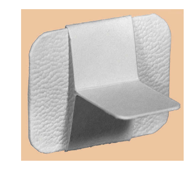
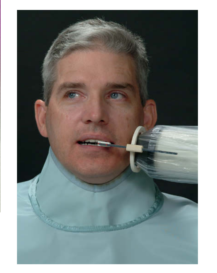
- Film / receptor placed intra-orally → Expose (the film & the patient) with x-ray beam → film processing → diagnostic image production
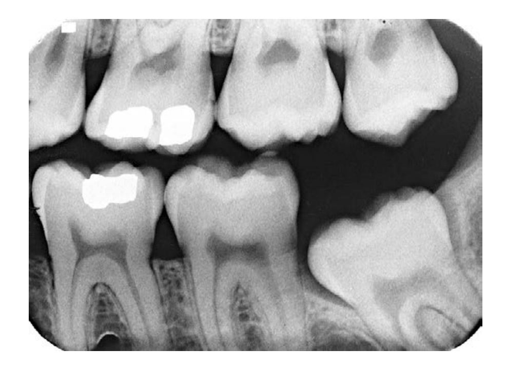
- Images are of black (radiolucent), white (radiopaque) and grey ‘shadows’
- Three types:
- Bitewing (BW), Periapical (PA) & Occlusal
- Digital or analogue
Left Posterior Bitewing (BW)
 |  |  |
 |  |  |
Learning Objectives4
- Understand the composition of a general analogue film
- What is a latent image?
- How is a latent image processed to form a final image?
- What are the factors that affect the final image quality?
- Understand how to assess faulty radiographs
Analogue Film Composition
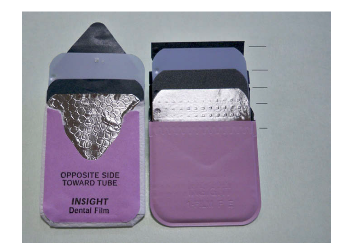
External Packet Components5
What you’ll see on the outside…
- Intra-oral film packet
- Plastic cover → moisture-proof
- Orientation dot (dot to the mesial)
- Inner paper wrap / black paper wrap → light-proof
- Lead foil backing → prevents residual radiation continuing on into patient’s tissues
- ANALOGUE FILM
Internal Film Structure6
What you can’t see inside…
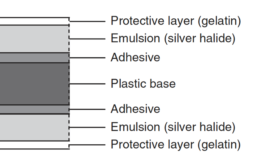
- Double emulsion film →
- Emulsion = where image is recorded
- Sensitive to x-rays, visible light & UV
- Double layers (to reduce radiation dosage)
- Base = film support
- Clear, transparent plastic
- Others:
- Gelatin layer x2 (outer protective layer)
- Adhesive layer x2 (between base & emulsion)
Fig. 4.3 Diagram showing the cross-sectional structure of double emulsion radiographic film.
Emulsion Components7
Emulsion
- Main components:
- Silver halide crystals (or grains) → sensitive to x-ray photons!
- Mostly silver bromide (Ag-Br) crystals →
- Vehicle / Gelatin matrix
- Suspends silver halide crystals
- Allows efficient chemical processing
- Overcoat
- To protect from damage eg. Scratch
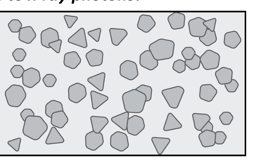
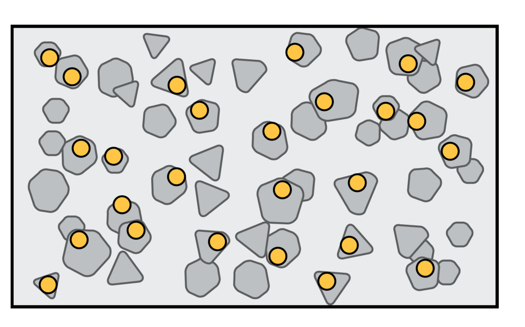
Latent Image Formation8
- = exposed film → CHEMICAL change in film emulsion after x-ray exposure
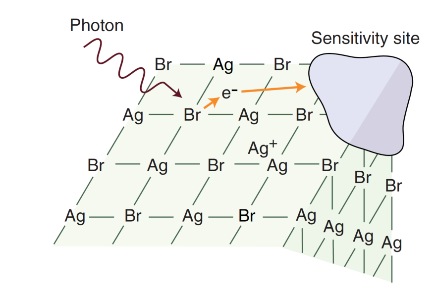
Silver bromide (Ag-Br) crystals in the emulsion layer have:
- Free silver ions (positively charged) and;
- Sulfur compounds aka ‘sensitivity site’ (SS)
Irradiated silver bromide release electrons and bind to ‘SS’
- SS become negatively charged
- Free silver ions are attracted to negatively charged SS to form neutral silver atom
Remember – only IRRADIATED (EXPOSED) Ag-Br crystals form latent image
Photon (wave shown) Ag (atom symbol) Br (atom symbol) e- (electron symbol) SS (sensitivity site shown as cloud) Br—Ag—Br Br—Ag+—Br Br Br—Ag—Br Ag—Ag Ag Ag—Br—Ag—Br—Ag—Br—Ag
 |  |
Chemical Processing Steps9
Latent Image to Final (Visible) Image
-
Processing tank (stainless steel)
-
CHEMICAL PROCESSING (4 steps)
- Developing solution
- Water
- Fixing solution
- Water & Dry & Mount
-
Other requirements:
- Timer
- Dry zone / area
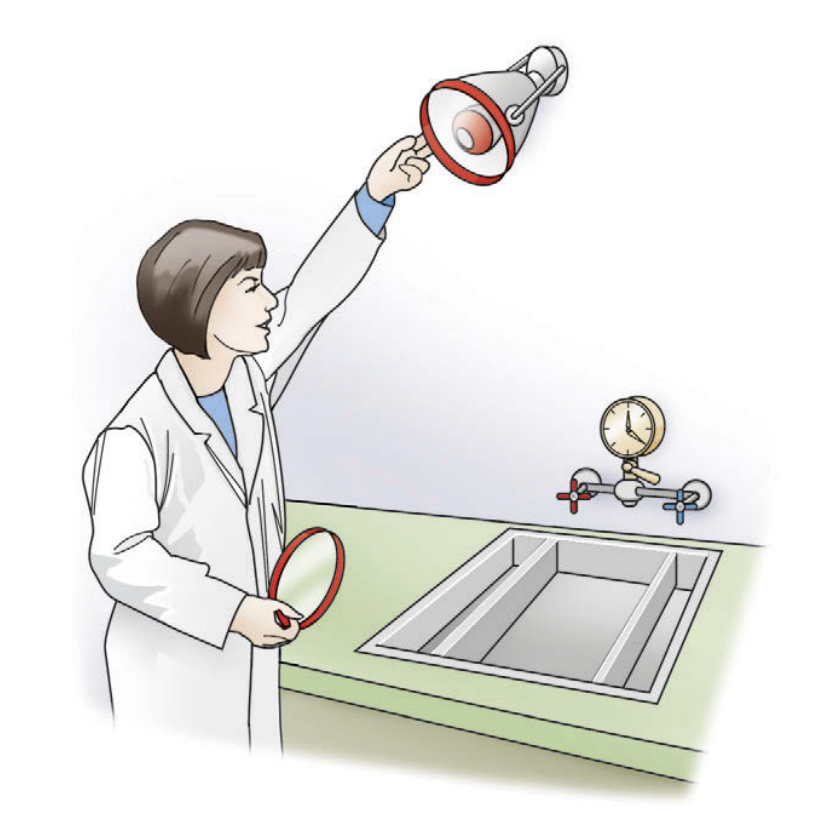
- Lightproof → ‘safelight’ Red GXB-2 filter (7.5-15W bulb)
- Humidity → 50-70% relative humidity
- Temperature → 20-25°C (room temp)
Developing Process10
Chemical Processing – 1. Developing
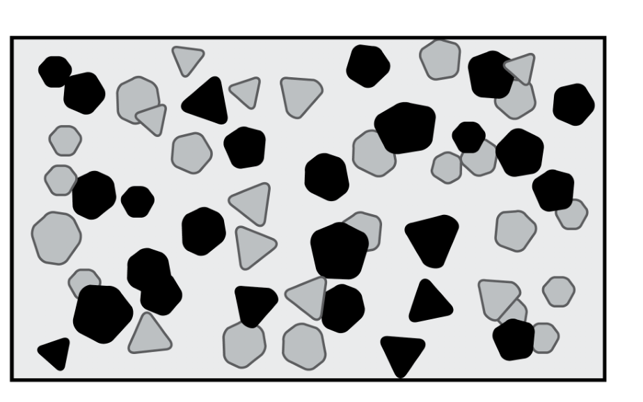
- Target: latent image / exposed silver halide crystals
- Chemicals used:
- Phenidone – converts latent image to metallic silver grains via oxidation
- Hydroquinone – reduces oxidated phenidone to help continuing its action
- Sodium sulphite (antioxidant preservative)
- Potassium carbonate (activator)
- Maintains alkaline environment (developers need pH ~10)
- Swells gelatin layer to let developing agents to diffuse more readily
- Benzotriazole (restrainer)
- Restrains developing unexposed Ag-Br crystals → reduces image fogging
- Glutaraldehyde
- Fungicide
- Water
- Duration: 3-6 minutes (depending on the temperature)
Rinsing Process11
Chemical Processing – 2. Rinsing
- Rinse the film in water with gentle agitation
- To:
- Prevent over-developing
- Over-developed images = dark final image (film fog)
- Buffer to neutral pH
- Prevent over-developing
- Duration: 20-30 seconds
Fixing Process12
Chemical Processing – 3. Fixing
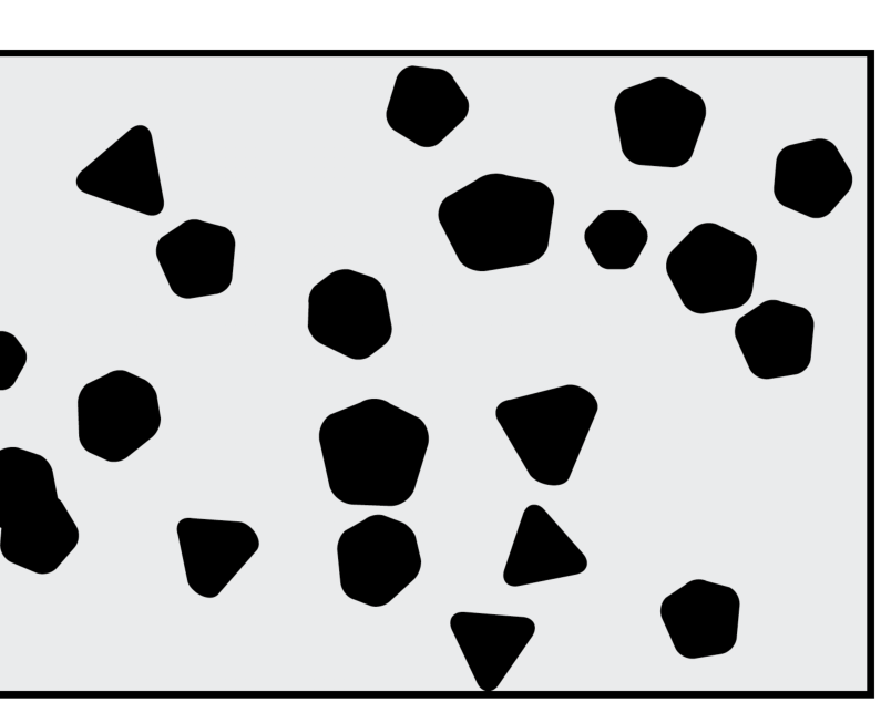
- Target = unexposed silver halide crystals
Chemicals used:
-
Ammonium thiosulphate – removes/dissolves unexposed silver halide crystals
-
Sodium sulphate (preservative)
-
Aluminium chloride (hardener)
- Reduces swelling of the gelatin from subsequent handling
-
Acetic acid (acidifier)
- Maintains acidic environment (pH 4-4.5) for the fixer
- Inactivates residual developing solution, if any
-
Duration: 8-10 minutes
Final Rinsing and Drying1314
Chemical Processing – 4. Final Rinsing
- Rinse in water (in bath + under running water)
- To:
- Prevent over-fixing
- Over-fixing causes light image
- Remove all the silver thiosulfate complexes (they cause fixer stains = obvious radiopaque areas on the final image)
- Prevent over-fixing
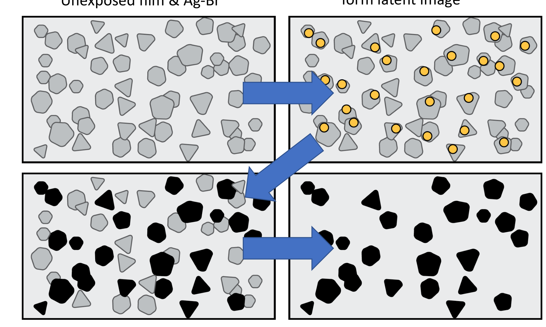
graph TD
    A[Unexposed film & Ag-Br] --> B[Only exposed Ag-Br form latent image]
    B --> C["Latent image become real image (image at this stage has fogging due to presence of remaining unexposed Ag-Br)"]
    C --> D[After fixing \(final image\)]
 |  |
 |
Darkroom Protocols and Automation
Daily Start-up Protocol15
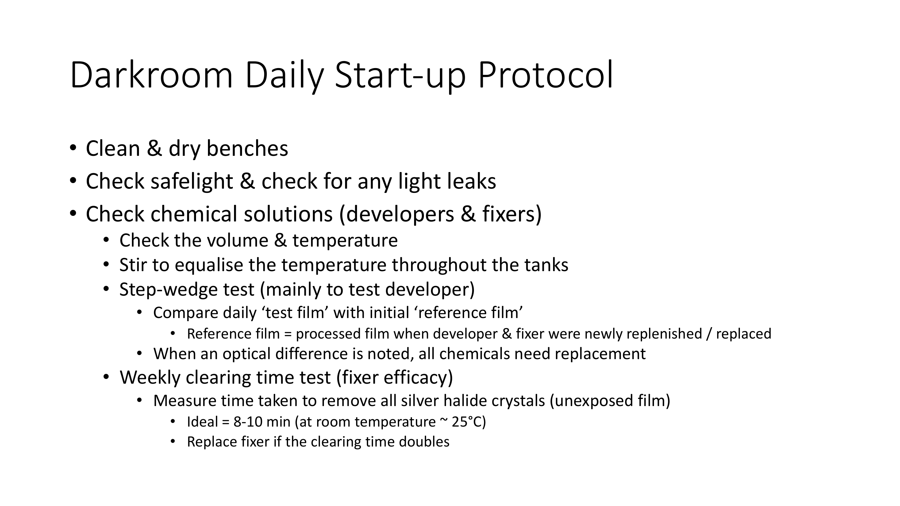
Darkroom Daily Start-up Protocol
- Clean & dry benches
- Check safelight & check for any light leaks
- Check chemical solutions (developers & fixers)
- Check the volume & temperature
- Stir to equalise the temperature throughout the tanks
- Step-wedge test (mainly to test developer)
- Compare daily ‘test film’ with initial ‘reference film’
- Reference film = processed film when developer & fixer were newly replenished / replaced
- When an optical difference is noted, all chemicals need replacement
- Compare daily ‘test film’ with initial ‘reference film’
- Weekly clearing time test (fixer efficacy)
- Measure time taken to remove all silver halide crystals (unexposed film)
- Ideal = 8-10 min (at room temperature ~ 25°C)
- Replace fixer if the clearing time doubles
- Measure time taken to remove all silver halide crystals (unexposed film)
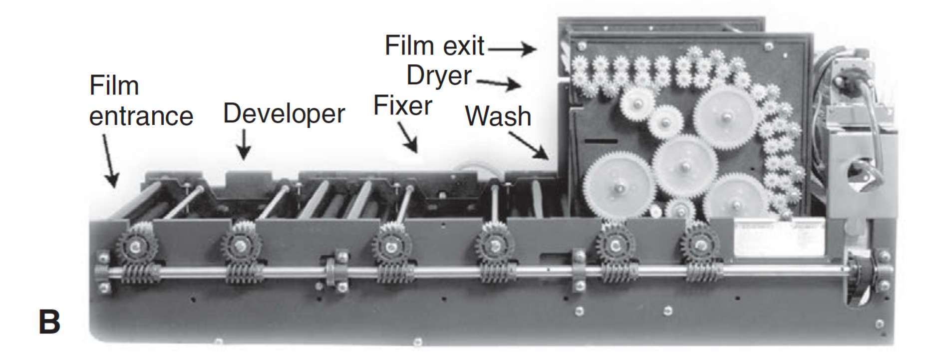
Automatic Processing Systems1617
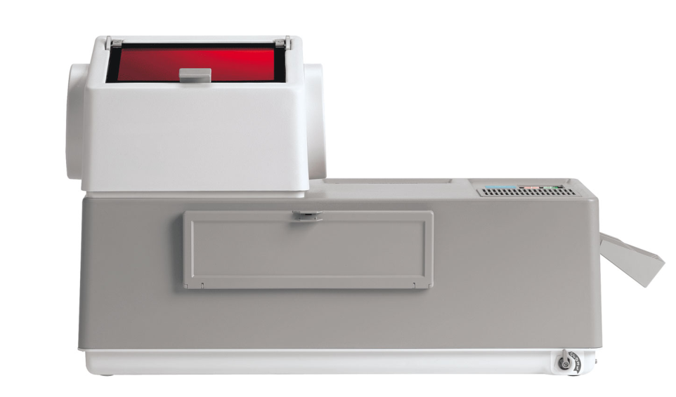
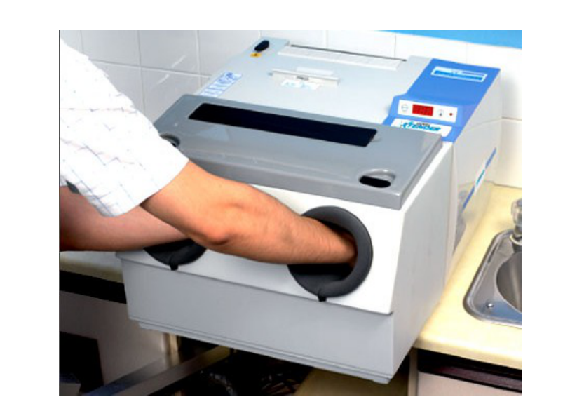
Automatic Processing
- Manual processing can take up to >10 min.
- Compact ‘darkroom’ unit
- No need for a separate dedicated darkroom
- Fast process
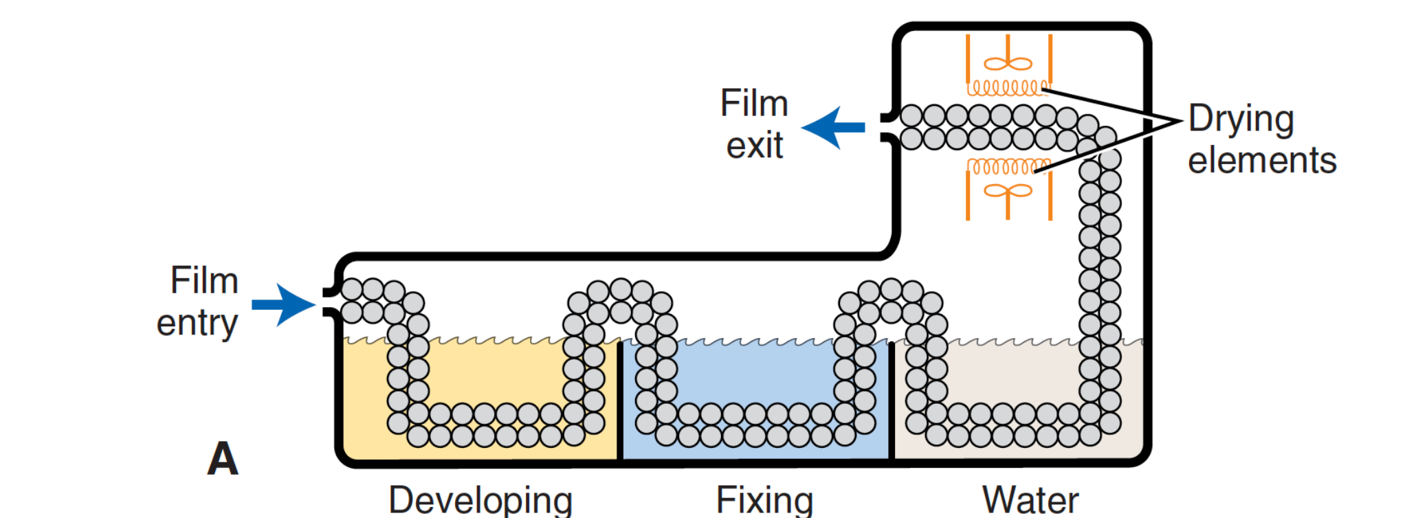
- Passes successively through the developer -> fixer -> water -> and drier (usually 5 min)
- High concentration of hydroquinone in developing solution
- Often, inadequately rinsed -> discolouration
graph TD
    A[Film entry] --> B[Developing solution]
    B --> C[Fixing solution]
    C --> D[Water wash]
    D --> E[Drying elements]
    E --> F[Film exit]
 |  |
 |  |
Film Viewing and Storage1819
Analogue Film Viewing
- Mount ONLY DRY films
- Check orientation
- Mandatory information on mounted films:
- Patient detail (name, gender, DOB)
- Date of exposure
- Type of film
- Institution / address of practice
- Exposure details (if possible)
- Light box
Film Storage
-
Medicolegally, all films must be kept for 7 years*
- If child, for 7 years after turning 18 years old
-
Stored in a cool, dry place
-
Check AHPRA / ARPANSA / Radiation Health (in QLD) annually for any change
 |  |  |
 |  |  |
 |  |  |
 |
Radiographic Film Faults20
Common Film Faults
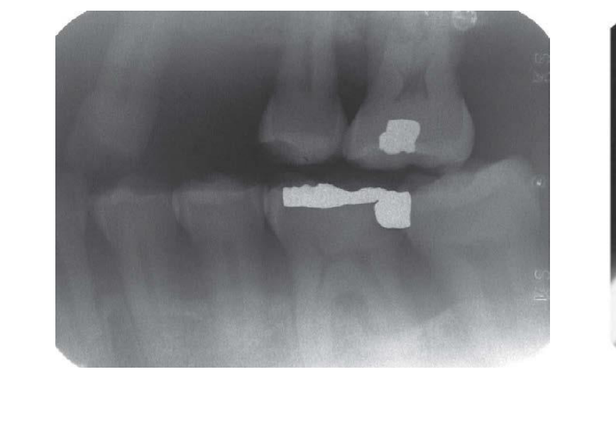
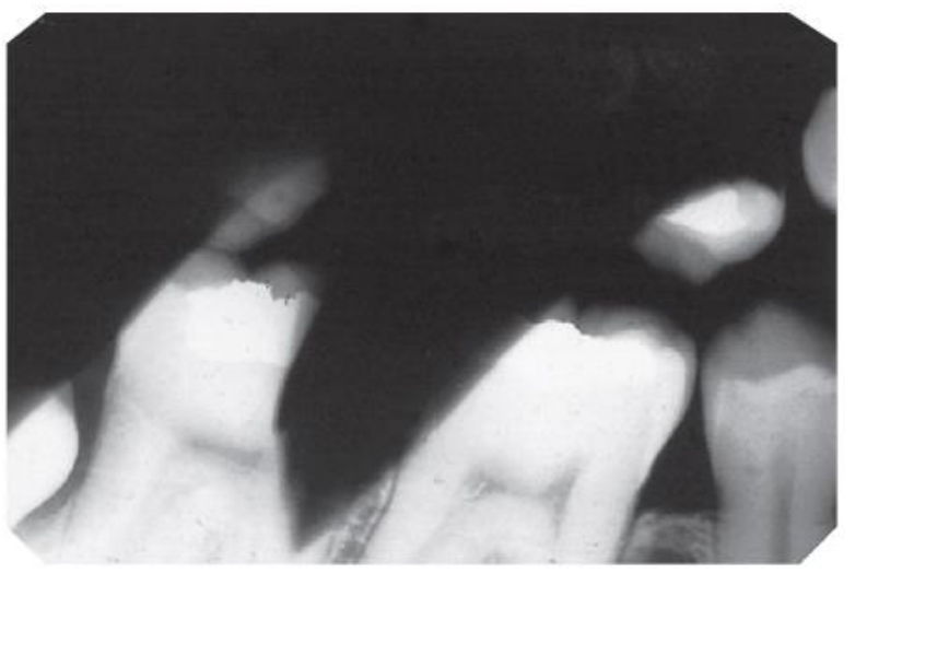
Processing and Handling Errors21
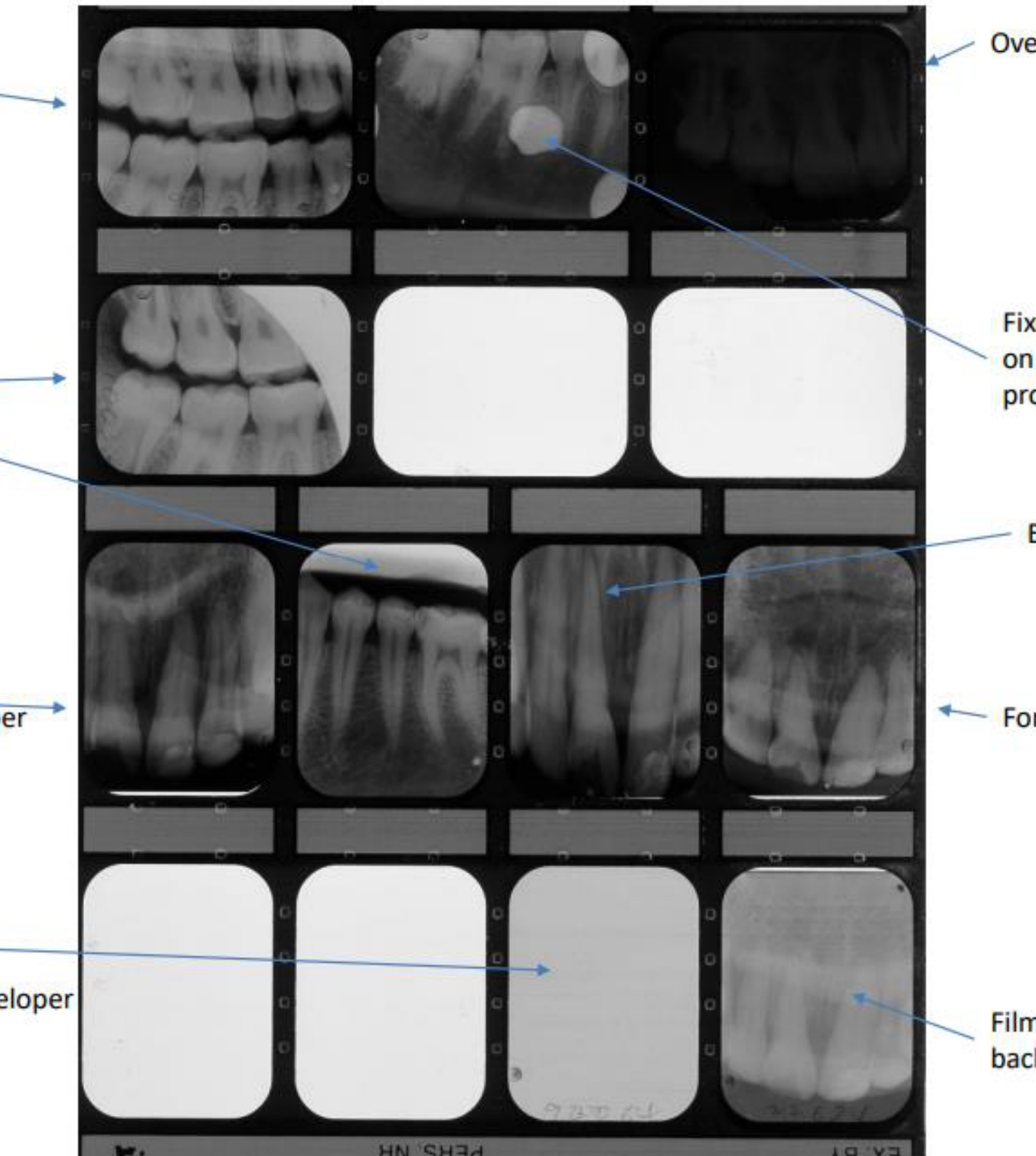
- Processing Errors - I
- Light exposure in darkroom
- Dark image = light leak into the darkroom
- Film fogging (poor contrast, dark image) = prolonged exposure to safelight
- Poor handling
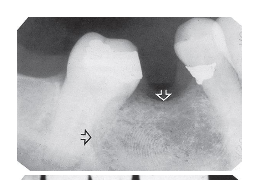
- Fingerprints
- Nails
- Bent films
- Developing errors
- Over-development → dark image
- Under-development → light image
- Contaminated film with developer before processing → black spots
The provided text is an order of operations for handling images and text:
Image Rules22
- Image Only: If the figure is an image with only labels or sparse text, output ONLY a brief 2-5 word description wrapped in “ tags.
- Image Context: If the text on the page only makes sense in the context of a figure or image (labels, names with no context), treat the whole page as a figure: wrap a single brief description in “ tags and output NOTHING ELSE.
- Constraints: NEVER output image descriptions as plain text outside of tags, and NEVER output standard HTML image tags (
<img src="...">), nor wrapper tags like<div>or<figure>.
 |  |  |
 |  |  |
Text Rules
- Extract all text and prioritize image text, using PDF text to resolve ambiguities.
- Format bold text using bolding.
- Ignore obviously corrupted text.
- Format tables in HTML (only tables, nothing else).
- Format flowcharts as tables.
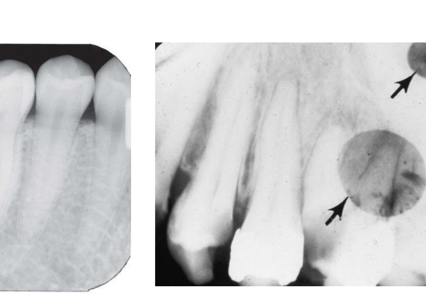
The input consists of six dental radiographs without any accompanying labels. Therefore, applying the Counting the Text and Image Rules, the appropriate response is a brief description of the entire figure containing the dental X-rays.
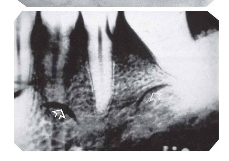
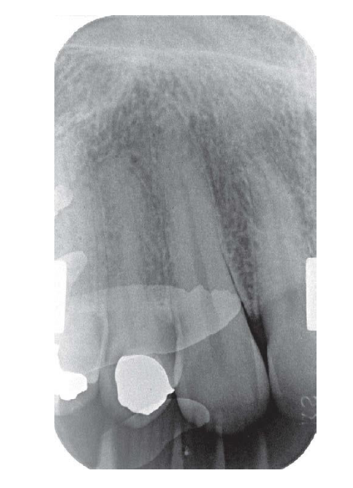
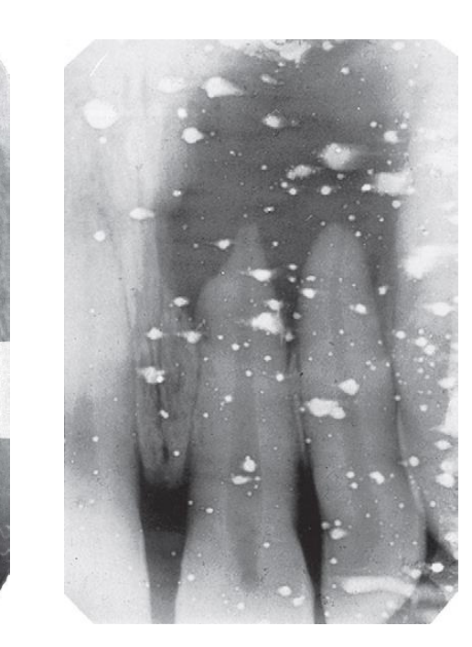
Fixing Errors23
- Over-fixing → light image (or clear)
- Under-fixing → dark image
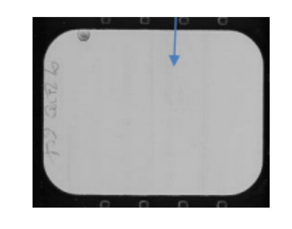
- Contaminated film with fixer before processing → white / clear spots
- Film in fixer before developer → clear image
 |  |
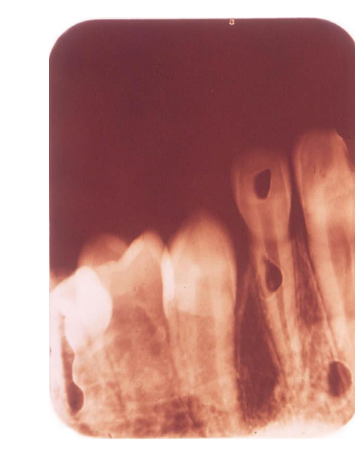 |  |
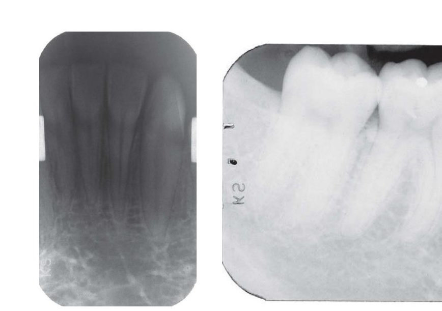
Rinsing Errors
- Inadequate rinsing → Brown image (usually from fixer staining)
- Over-rinsing → emulsion peel, i.e., no image
Beam Related Errors2425
- Exposure setting errors
- Underexposure → light image
- Insufficient mA
- Insufficient kVp
- Insufficient time
- Long film-source distance
- Film reversed in mouth
- Overexposure → dark image
- Excessive mA
- Excessive kVp
- Excessive time
- Underexposure → light image
- Beam misalignment → Cone-cutting (partial image)
Causes of Faded or Washed Out Images
Positive-Fading or Washed Out (Fig. 5-34)26
Causes in Exposure Factors
- Incorrectly installed long-focus cone tip
- Film-source distance is too far
- Excessive kVp
- Power-failure during exposure
- Not using film cassette or trouble with cassette (bending)
Causes in Processing
- Improper time-temperature setting for development (too cool)
- High concentration of developer solution
- Stale developer solution
- New and fresh fixer solution
- Failure to fix (insufficient time in fixer)
- Developer has not reached the film during processing
- In prolonged processing, the film was agitated too little
Negative-Fading or Densification (Fig. 5-35)
-
Insufficient time
-
Insufficient current (mA)?
-
Insufficient kVp
-
Power-failure during exposure
-
Not using film cassette or trouble with cassette (bending)
-
Inadequate or old developer solution
-
Excessive development time for solution temperature
-
Old fixer solution
-
In new film processing, insufficient agitation time of the developer
White Blends (Fig. 5-36)
Cause in Exposure Factors
- Improperly exposed or old double emulsion X-ray films
- Film brought into contact with fluorescent lamps
Cause in Processing
- Improper time-temperature setting for development (too cool)
- Undiluted or insufficiently diluted developer solution
- Stale developer solution
- Improper film sorting class
- Improper storage of films in humid or hot conditions
Radiation (Fig. 5-37)
-
Wrong focal length for the case
-
X-ray tube malfunction
-
Long exposure time (usually not more than 12 seconds)
-
Not enough kVp
-
Failure of the X-ray machine
-
Improper time-temperature setting for development (too cool)
-
Long development time
-
Too much agitation
-
Inadequate or old developer solution
-
Improper film sorting class
-
Operator’s overexposure of the film (excessive-dose)
-
Operator’s underexposure of the film (insufficient-dose)
-
Failure of the X-ray machine
Dusty Spots (Fig. 5-38)
- External objects in the field of the beam
- Operator’s overexposure of the film (excessive-dose)
Radioactivity (Fig. 5-39)
- Kernel of radioactive element in the film
Chair, Acetone, and Oil (Fig. 5-40)
- Overly dense areas in the film
- Operator’s overexposure of the film (excessive-dose)
Handlers Hallmarks (Fig. 5-41)
- Operator’s overexposure of the film (excessive-dose)
Bibliography27
Fifth Edition Essentials of Dental Radiography and Radiology Eric Whaites, Nicholas Drage CHURCHILL LIVINGSTONE ELSEVIER
ORAL RADIOLOGY Principles and Interpretation Edition 7 Stuart C. White, Michael J. Pharoah ELSEVIER
 |  |
 |
Footnotes
-
Original PDF page 1: L3 Analogue Films & Film Faults, p.1 ↩
-
Original PDF page 2: L3 Analogue Films & Film Faults, p.2 ↩
-
Original PDF page 3: L3 Analogue Films & Film Faults, p.3 ↩
-
Original PDF page 4: L3 Analogue Films & Film Faults, p.4 ↩
-
Original PDF page 5: L3 Analogue Films & Film Faults, p.5 ↩
-
Original PDF page 6: L3 Analogue Films & Film Faults, p.6 ↩
-
Original PDF page 7: L3 Analogue Films & Film Faults, p.7 ↩
-
Original PDF page 8: L3 Analogue Films & Film Faults, p.8 ↩
-
Original PDF page 9: L3 Analogue Films & Film Faults, p.9 ↩
-
Original PDF page 10: L3 Analogue Films & Film Faults, p.10 ↩
-
Original PDF page 11: L3 Analogue Films & Film Faults, p.11 ↩
-
Original PDF page 12: L3 Analogue Films & Film Faults, p.12 ↩
-
Original PDF page 13: L3 Analogue Films & Film Faults, p.13 ↩
-
Original PDF page 14: L3 Analogue Films & Film Faults, p.14 ↩
-
Original PDF page 15: L3 Analogue Films & Film Faults, p.15 ↩
-
Original PDF page 16: L3 Analogue Films & Film Faults, p.16 ↩
-
Original PDF page 17: L3 Analogue Films & Film Faults, p.17 ↩
-
Original PDF page 18: L3 Analogue Films & Film Faults, p.18 ↩
-
Original PDF page 19: L3 Analogue Films & Film Faults, p.19 ↩
-
Original PDF page 20: L3 Analogue Films & Film Faults, p.20 ↩
-
Original PDF page 21: L3 Analogue Films & Film Faults, p.21 ↩
-
Original PDF page 22: L3 Analogue Films & Film Faults, p.22 ↩
-
Original PDF page 23: L3 Analogue Films & Film Faults, p.23 ↩
-
Original PDF page 24: L3 Analogue Films & Film Faults, p.24 ↩
-
Original PDF page 25: L3 Analogue Films & Film Faults, p.25 ↩
-
Original PDF page 26: L3 Analogue Films & Film Faults, p.26 ↩
-
Original PDF page 27: L3 Analogue Films & Film Faults, p.27 ↩