Dentofacial Proportions
p. 160: A systematic examination of facial and dental appearance should be done in the following three steps:
- Facial proportions in all three planes of space (macro-esthetics). Examples of problems that would be noted in this first step would be asymmetry, excessive or deficient face height, mandibular or maxillary deficiency or excess, and so on. In performing this evaluation, keep in mind that both the evolutionary and prenatal development of the face can provide additional insight into the origin and significance of unusual facial morphology.
- The dentition in relation to the face (mini-esthetics). This includes the display of the teeth at rest, during speech, and on smiling. It includes such assessments as excessive gingival display, inadequate anterior tooth display, inappropriate gingival heights, and the extent of the buccal corridors (the dark spaces in the corners of the mouth beyond the teeth).
- The teeth in relation to one another (micro-esthetics). This includes assessment of tooth proportions in height and width, gingival shape and contour, connectors and embrasures, black triangular holes, and tooth shade
Describe ideal proportions from full-face (symmetry) and lateral (A-P/vertical) aspects.
01 - Facial Form Analysis 10 6 Orthodontic Diagnosis L4 Level II Unit B
Points of view
Facial form analysis is completed from the frontal view and the lateral view . This can be considered macroesthetics in the systematic examination of facial and dental appearance
Frontal View
- Categories analyzed
- Symmetry
- Vertical and transverse facial proportions
- Tooth display
Symmetry
Jaw Asymmetry
- In terms of deviation of the mandible, a up to a 3mm deviation of the chin is not easily noticable but 4mm is very likely to be noticed
Dental Midline Asymmetry
- Dental midline off the center of the face becomes noticable when it exceeds about 3mm
Transverse facial Proportions
- Analyzing transverse facial proportions is to evaluate proportions across the width of the face. This is where the facial fifths are important
An ideally proportional face can be divided into central, medial, and lateral equal fifths
- The separation of the eyes and the width of the eyes should be equal
- Nose and chin should be centered within the central fifth (width of the nose should be same or slightly wider than the central fifth)
- the interpupillary distance should equal the width of the mouth

Vertical Facial Proportions
Vertical facial proportions are best evaluated in the context of the facial thirds. The lower third can be further subdivided into thirds
-
The three vertical faction regions should be about the same size
- Hairline to the bridge of the nose (upper third)
- Bridge of the nose to bottom of nose (mid-face)
- Bottom of nose to bottom of chin (lower face)
-
In modern populations the lower third of the face is usually slightly longer than the central third
-
Lower facial thirds
-
From the base of the nose to the mouth : ideally one-third of the total height
-
From mouth to the bottom of chin is two-thirds
 Image 1: Normal vertical proportions, frontal view.
Tooth display
Tooth display falls under step 3 “Mini-esthetics”. Conversely Miniesthetics can be subdivided into parts
- Anterior tooth display
- Transverse dimensions of the smile relative to the upper arch (buccal corridor)
- The smile arc
- Close up dental appearance (proportions and shape of teeth and gingival contours )
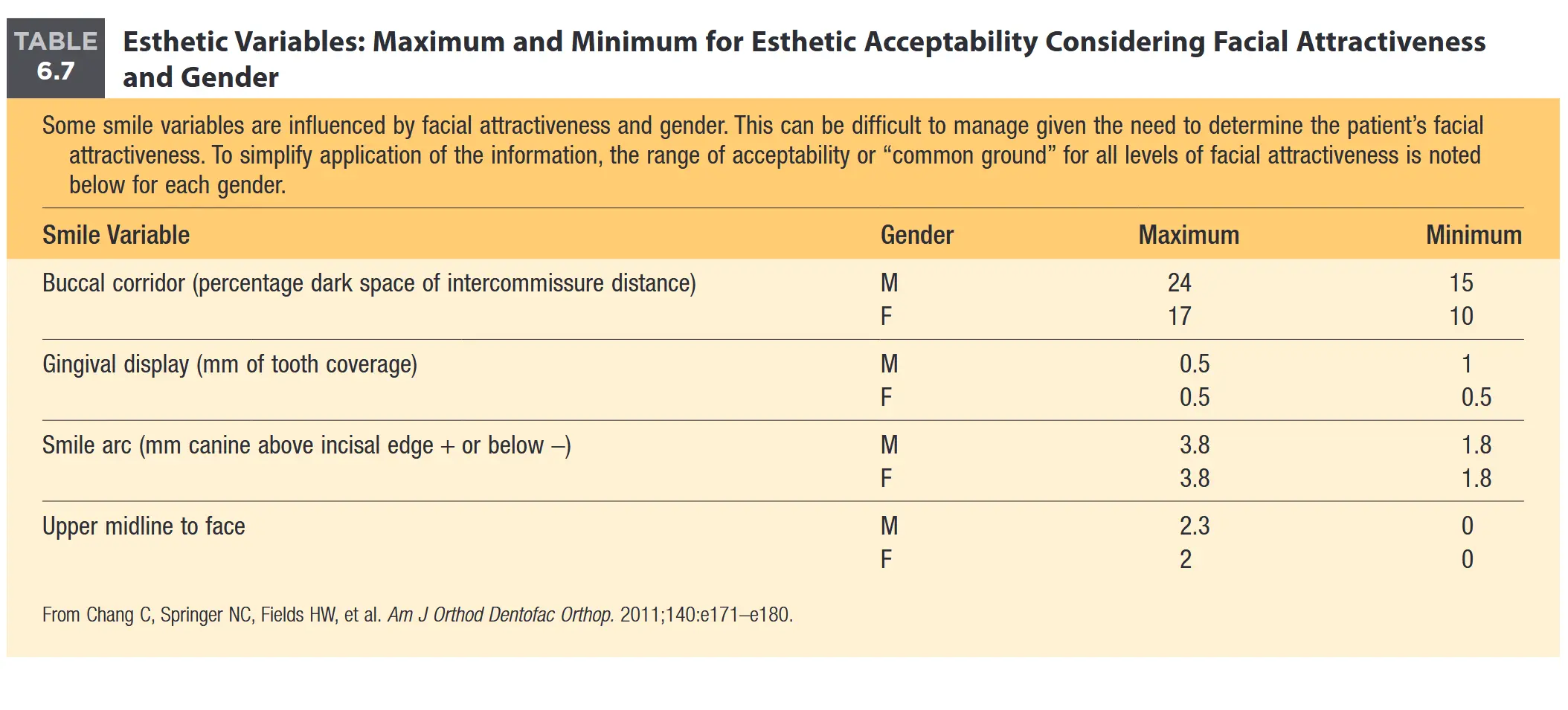
Anterior Tooth Display
- Maxillary Incisor display at rest
- can be zero but is usually 2-4 mm
- Maxillary Incisor display on smile
- Ideal: slightly below the gingival margin with 2mm of tooth coverage so that most but not quite all of the upper incisor can be seen (i.e. between 75% - 100 % exposure of the incisor)
- acceptable range is 1mm up to 4 mm coverage of the incisor crown
Posterior Tooth Display: Buccal Corridors
- Buccal corridor: The distance between the maxillary posterior teeth and the inside of the cheek
Measurement
This one depends on gender but ideal is :
- males : 15 -24 mm
- females 10 - 17 mm
**Smile Arc
The Relationship of the curvature of the lower lip on smile to the contour of the maxillary dentition
- The ideal smile arc is where the curvature of the lowerlip matches the contour of the maxillary dentition
- Nomenclature
- Ideal smile arc: termed consonant
- Non - ideal/ flattened : termed non- consonant

Lateral View
Analyzed in the lateral view:
- A - P Jaw Relationships
- Incisors protrusion or retrusion
- Vertical facial thirds
The three goals of lateral facial profile analysis :
- Establishing whether the jaws are propotionately positioned in the anteroposterior plane of space
- Evaluation of lip posture and incisor prominence
- Reevaluation of vertical facial proportions and evaluation of mandibular plane angle
A - P Jaw relationships from lateral view facial analysis
Patient Head Position
Make sure the patient is in natural head position
To evaluate draw two lines:
- Dropped from bridge of the nose to base of upper lip
- Extending from base of upper lip to the point of the chin
- A convexity in the lines indicates class II jaw relationships
- A concavity indicates Class III jaw relationships
- If they are straight it indicates a Class I jaw relationship ideal

Lip Posture and Incisor Prominence
fill in later
Contents
Describe methods, objectives, and limitations of facial form analysis.
fill in later
Contents
Perform a facial form analysis.
Cephalometric Analysis
02 - Cephalometric Tracing Techniques 03 - Cephalometric Superimposition 10 6 Orthodontic Diagnosis L4 Level II Unit B
Discuss the history and two major uses of cephalometric radiography.
History Cephalometrics was introduced in 1934 by Hofrath in Germany and Broadbent in the US . The original purpose was research on growth patterns in the craniofacial complex.
Important advantages of cephalometric radiography:
- The radiographic view makes it possible to directly view the relationship of the dental arches to the underlying jaw structures, and to evaluate the relationship of the jaws to each other and to the cranial base.
- Serial cephalometric radiographs make it possible to evaluate both growth changes and response to treatment in way that was not possible previously
Identify and trace landmarks for the cranial base, maxilla, mandible, and dentition.
Take key landmarks from
Workbook then take the keys from the L4, and then the textbooks
Landmarks
Landmarks come from the 5 functional units of the craniofacial complex . The 5 units are:
- The crainum and cranial base
- The skeletal maxilla and nasomaxillary complex
- the skeletal mandible
- the maxillary teeth and alveolar process
- the mandibular teeth and alveolar process

 Image 1: Anatomic location of major cephalometric landmarks. Image 1: Anatomic location of major cephalometric landmarks. |  Image 2: Linear measurements frequently made on a ceph tracing. Image 2: Linear measurements frequently made on a ceph tracing. |
 Image 3: Angular measurements frequently made on a ceph tracing. Image 3: Angular measurements frequently made on a ceph tracing. |  |
Landmarks of the cranial base
There are two main landmarks :
- Sella (s)
- Indicates the posterior end of the anterior cranial base, and is located in the center of the cavity of sella turcica
- Nasion (Na)
- Indicates the front end of the anterior cranial base, and is located at the anterior end of the junction between the nasal and frontal bones
 Image 1: Sella, the center of sella turcica, the midline depression in the sphenoid bone that houses the pituitary gland. Image 1: Sella, the center of sella turcica, the midline depression in the sphenoid bone that houses the pituitary gland. |  Image 2: Nasion, the anterior-superior point at the junction of the nasal and frontal bones. Image 2: Nasion, the anterior-superior point at the junction of the nasal and frontal bones. |
Landmarks of the Maxilla
The three main landmarks for the maxilla are
- Anterior nasal spine (ANS)
- Inidcates the front end of the maxilla, and is located at the tip of the anterior nasal spine
- Point A (A)
- Associated with the anterior maxilla, located at the innermost point of the contour of the premaxilla between the anterior nasal spine and the incisor tooth
- Posterior Nasal spine (PNS)
- Indicates the posterior end of the maxilla and is located at the tip of the posterior spine of the palatine bone, at the junction of the hard and soft palates
 Image 1: Close-up view of the maxilla as seen in a ceph. Image 1: Close-up view of the maxilla as seen in a ceph. |  Image 2: Anterior maxilla landmarks. Image 2: Anterior maxilla landmarks. |
 Image 3: Posterior maxilla landmark. Image 3: Posterior maxilla landmark. |
Landmarks of the Mandible
There are 5 important landmarks for position and orientation of the mandible (image 1):
Point B (B) – indicates the anterior part of the bony base of the mandibular dentition, and is located at the innermost point on the contour of the mandible between the incisor tooth and bony chin (image 2).
Pogonion (Pg) – the most anterior point on the contour of the chin (image 3).
Menton (Me) – the most inferior point on the mandibular symphysis (i.e., the bottom of the chin) (image 3).
Gnathion (Gn) – the center of the inferior contour of the chin, halfway between pogonion and menton (image 3).
Gonion (Go) – indicates the angle of the mandible, and is located at the center of the inferior contour of the mandibular angle (image 4).
 Image 1: Close-up of mandible as seen on a ceph. Image 1: Close-up of mandible as seen on a ceph. |  Image 2: B point, the junction between the skeletal mandible and the alveolar process. Image 2: B point, the junction between the skeletal mandible and the alveolar process. |
 Image 3: Landmarks on the chin. Image 3: Landmarks on the chin. |  Image 4: The landmark for the back of the body of the mandible. Image 4: The landmark for the back of the body of the mandible. |
Landmarks of the dentition
Four landmarks typically represent the a-p and vertical position of the incisor and molar teeth in each arch:
Upper incisor (U1) – maxillary central incisor tip)
Lower incisor (L1) – mandibular central incisor tip)
Upper molar (U6) – maxillary 1st molar, mesial cusp tip
Lower molar (L6) – mandibular 1st molar, mesial cusp tip
 Image 1: Close-up view of the maxillary and mandibular teeth as seen on a ceph, with the tooth landmarks identified. Image 1: Close-up view of the maxillary and mandibular teeth as seen on a ceph, with the tooth landmarks identified. |  Image 2 Image 2 |
Completing Tracings
- Sella (s)
- Appears as a depression in the sphenoid bone that contains the pituitary gland
- Draw the contour of the depression in the bone extending anteriorly and posteriorly over the edges of the concavity then mark pint S in the center of the concavity .. Make sure to extend the line forward along the floor of the anterior cranial base to help do superimpositions
- Appears as a depression in the sphenoid bone that contains the pituitary gland
- Nasion (N)
- Draw the outer surface of the nasal and frontal bones past the junction , then draw a suture between the bonest. Identify point NA as the place where these lines intersect
 Image 1: Outline of sella turcica. Image 1: Outline of sella turcica. |  Image 2: Tracing the fronto-nasal junction to locate nasion. Image 2: Tracing the fronto-nasal junction to locate nasion. |
- ANS
- Trace the superior and inferior surfaces of the anterior nasal spine and mark its tips as ANS. Then follow the external contour of the bone downward toward the upper incisor, and mark point A at the depth of this concave line
- Point A
- At the junction between the skeletal maxilla and the maxillary dentoalveolar process, is the innermost point on the contour of the premaxilla between the ans and the incisor
- PNS
- Trace the inner contour of the anterior maxillary alveolar process and continue posteriorly along the roof of the mouth to the end of the bony outline. Mark the end of the palatal bone contour as PNS
 Image 1: Tracing the contours of the anterior maxilla to locate ANS and point A. Image 1: Tracing the contours of the anterior maxilla to locate ANS and point A. |  Image 2: Tracing the contour of the posterior maxilla to locate PNS. Image 2: Tracing the contour of the posterior maxilla to locate PNS. |
- Point B
- Trace the bony chin. Include the inner aspect of the symphysis. Follow the external contour of the bone from the chin upward toward the incisor and mark point B as the depth of the concave line
- Pogonion
- The most prominent point on the anterior aspect of the bony chin.
- Mention is the most inferior point on the bony chin
- Gnathion
- the point on the anterior inferior contour of the chin halfway between pogonion and mention
 Image 1: Tracing the contour of the mandibular symphysis to locate point B. Image 1: Tracing the contour of the mandibular symphysis to locate point B. |  Image 2: Locating pogonion, gnathion and menton (top to bottom order) on the contour of the bony chin. Image 2: Locating pogonion, gnathion and menton (top to bottom order) on the contour of the bony chin. |
- Gonion
- Center of the inferior contour of the mandibular angle
- Follow the lower border of the mandible posteriorly around the mandibular angle and up the posterior surface of the ramus. Mark the center of the curvature at the gonial angle point Go
- Center of the inferior contour of the mandibular angle

- Orbitale
- Trace the orbital rims , and trace the most inferior point on the lower border of the orbit. OR if you you can see both sides separately trace both and locate the point halfway between the two sides
- IAN and crown of unerupted third molar
- these structures are useful as stable areas for superimposition
 Image 1: Tracing the orbital rim to locate point Or. Don’t confuse the dotted line behind the orbit with the orbital rim—a common tracing mistake. Image 1: Tracing the orbital rim to locate point Or. Don’t confuse the dotted line behind the orbit with the orbital rim—a common tracing mistake. |  Image 2: Tracing the outline of the neurovascular bundle below where it enters the lower part of the ramus, and the outline of a third molar at the stage of crown formation. Image 2: Tracing the outline of the neurovascular bundle below where it enters the lower part of the ramus, and the outline of a third molar at the stage of crown formation. |
- Drawing lips and incisor teeth
- its important to get the root inclination correct
Evaluate if incisors are retrusive, proper, or protrusive relative to supporting bone.
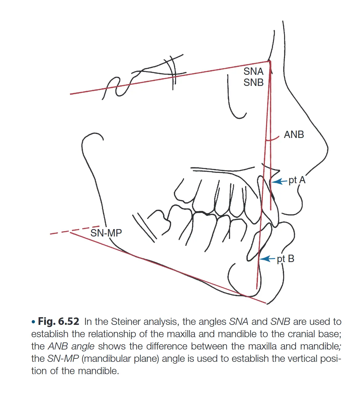
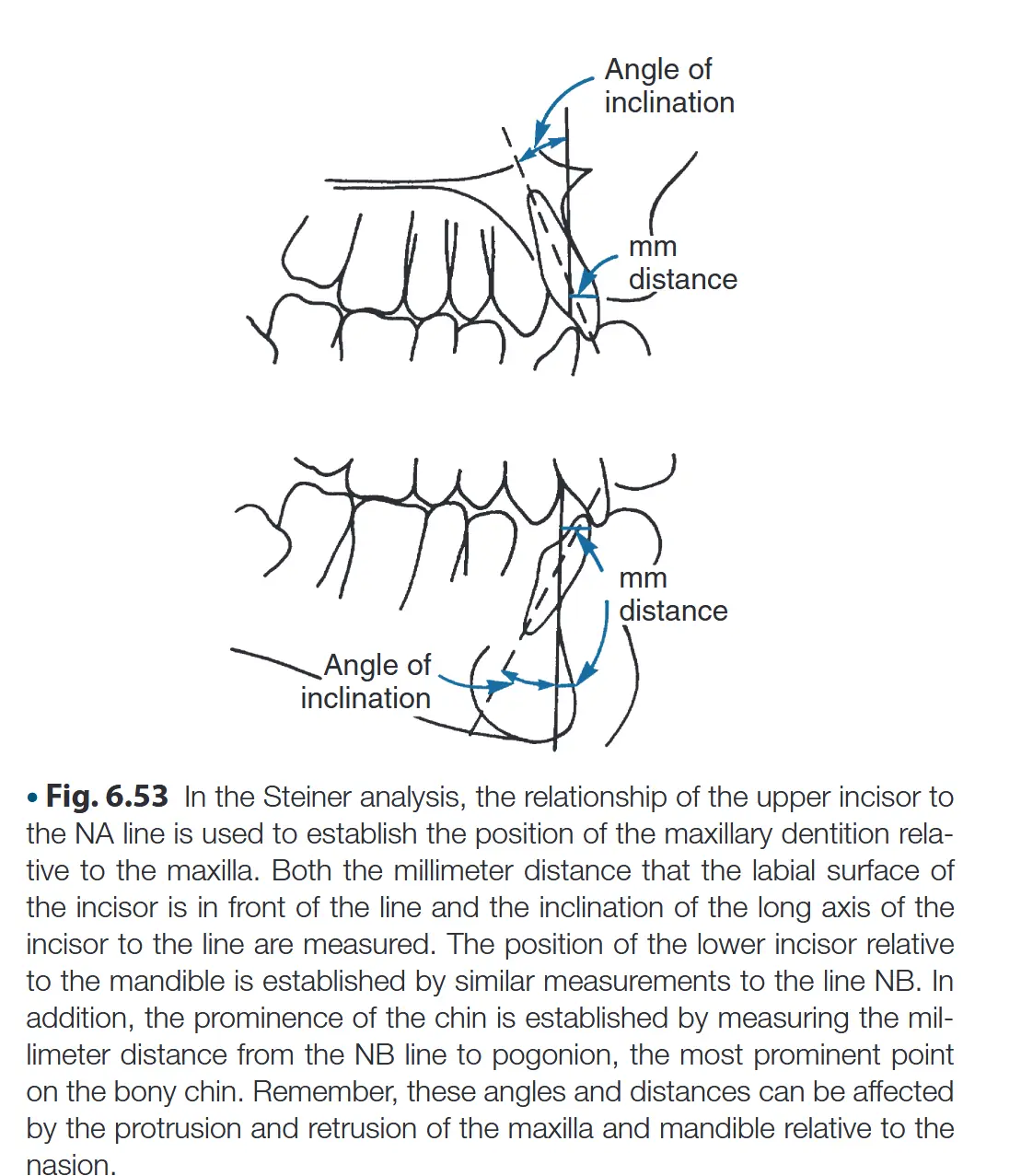
Upper incisors
- The relationship of the upper incisor to the NA line is used to establish the position of the maxillary dentition relative to the maxilla
- both the millimeter distance and the inclination of the long axis of the incisor to the line are measures
Lower incisors
- The position of the lower incisor relative to the mandible is established by similar measurements to the line NB as the upper oens. In addition the prominence of the chin is establisehd by measuring the millimeter distance from the NB line to pogonion, the most prominent point of the bondy chin
Evaluate jaw relationships to the cranial base and each other.
The objective of cephalometric analysis is to establish the relationship of the facial units in the antero-posterior and vertical planes of space
Vertical Proportions
This is also known as the Sassouni analysis
Five horizontal reference lines :
- S-N, the inclination of the anterior cranial base
- True horizontal, the visual axis which is drawn perpendicular to the true vertical through the lower border of the orbit (Or)
- ANS-PNS, the palatal plane
- Functional occlusal plane, drawn along the occluding surfaces of the posterior teeth
- Go-Gn, the mandibular plane
In a well-proportioned face the horizontal anatomic planes tend to converge toward a single point.
- If the planes intersect relatively close to the face and diverge quickly as they pass anteriorly the facial proportions are long anteriorly and short posteriorly this is known as : *skeletal open bite *
- If the planes are nearly parallel so that they converge far behind the face and diverge only slowly as they pass anteriorly, there is a skeletal predisposition toward anterior deep bite and the condition is termed *skeletal deep bite *
Anterior - Posterior Proportions
N- Perpendicular
Examining the position of the N perpendicular relative to point A or point B is a good way to quickly analyze A-P relatinships
- Point A
- Should be one or slightly in front of the line
- 2mm in front with a range of 0-4 mm
- Point B
- should be slightly but not very far behind it
- 2mm behind with a range of -4 to 0 mm
- Difference between the lines through points a and B shouldn’t be more than 4mm otherwise the teeth can’t occlude properly

ANB angle
- draw NA and NB lines and measure angle between them to judge how greater the difference aw position is ( normal is 2.8 degrees in whites and 5.5 degrees in blacks )
SNA and SNB
- Can be measured to determine whether the maxilla or the mandible was in the wrong position
- SNA norms
- 81 degrees in white
- 84.7 degrees in black
- SNB norms
- 78.2 degrees in white
- 79.2 degrees in black
- SNA norms
 Image 1: The ANB angle is an estimator of the a-p relationship of the jaws. It is quite small in patients with normal jaw relationships, like this one. Image 1: The ANB angle is an estimator of the a-p relationship of the jaws. It is quite small in patients with normal jaw relationships, like this one. |  Image 2: The SNA and SNB angles indicate the degree of protrusion of the jaws relative to the cranial base, but they must be used carefully because the reference standards assume a normal inclination of SN, and we have seen already that this is not always correct. Image 2: The SNA and SNB angles indicate the degree of protrusion of the jaws relative to the cranial base, but they must be used carefully because the reference standards assume a normal inclination of SN, and we have seen already that this is not always correct. |
Maxillary incisor to SN
- U1 to SN plane measures maxillary incisor angular
Mandibular incisor to Go-GN
- Mandibular incisor to Go-GN measures the angulation of the lower incisors
Need to figure out
- Intereicincisal angle and what it means
- Maxillary incisor to Na
- Mandibular incisor to NB
- PG to N-perpendicular
Compare measurement analysis versus template analysis.
To do
Contents
Complete overall, maxillary, and mandibular superimpositions on composite tracings.
to do still
Contents
Describe changes in composite tracings related to growth or treatment.
To do
Space Analysis
Identify the four major assumptions of space analysis regarding growth.
Tanaka- Johnston Prediction table assumptions
- There is a correlation between the size of erupted mandibular incisors and the size of the remaining unerupted maxillary and mandibular canines and premolars
- The patient fits the population for the prediction table (caucasian/ Northern European decent )
- All succedaneous teeth are developing normally
- Assumption that the arch dimensions do not increase in growth.
- Position of the incisors wlil not change in a way that increases or decreases arch circumference and available space
- Assumption that the mesial shift of first molars can be predicted accurately (at least in a child with a class I skeletal pattern)
Discuss why accuracy decreases in non-Class I jaw relationships.
There are two main reasons as to why accuracy decreases in non-class I jaw relationships
Reason 1
The first reason is due to assumption 5 that the position of the incisors will not change in a way that increases or decreases arch circumference and available space
- In class II the lower incisors will tip facially
- this increases space in the lower arch while upper incisors may move either facially or lingually
- In class III patients the lower incisors are likely to tip lingually
- this increases space in the lower arch
- upper incisors often tip facially, increasing space in the upper arch
Reason 2
- Assumes that a mesial shift of molars can be predicted accurately
- The different partn of molar shift in children with skeletal class II or class III growth patterns restricts the applicability of space analysis
Identify necessary diagnostic materials.
- Dental casts
- Sketched or digital image of patients profile
- Measuring Instrument : Boley gauge
- A space analysis form (form 42)
- Pencil
Perform a space analysis as described in the practical exercise.
Workbook to fill this in
Interpret results considering retrusive or protrusive incisors.
Aside from the usual materials also check the practical exercises
- the final writeup in the practical exercises is pretty good for one of these scenarios
Systematic Description
Identify the five major characteristics of systematic malocclusion description.
Contemporary Orthodontics (sixth edition) Annotations
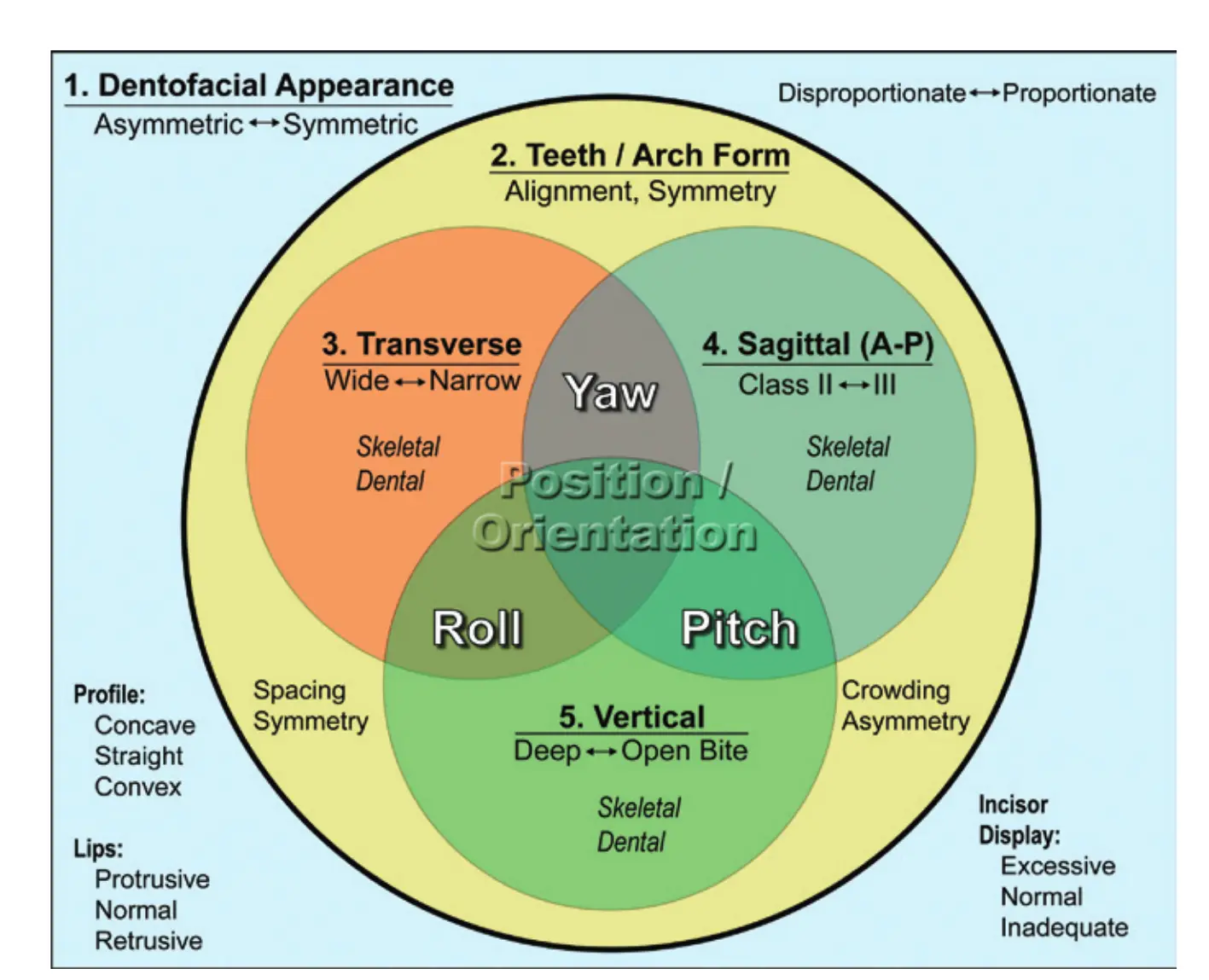
The five major characteristics of the systemic malocclusion description , also known as the Ackerman and Proffit Classification
- Dentofacial appearance
- Teeth/Arch form
- Transverse characteristics
- Sagittal (A-P)
- Vertical
1. Dentofacial appearance
- Dentofacial appearance consists of
- Symmetric analysis
- Proportionality
- Profile
- concave
- straight
- convex
- Lips
- protrusive
- normal
- retrusive
- Incisor display
- Excessive
- Normal
- Inadequate
2. Teeth / Arch Form
The analysis of the the teeth /arch form consists of
-
Alignment
-
symmetry
-
Crowding
-
Spacing
-
when doing this sort of analysis, its helpful to categorize that there are two important lines in the dentition 05 - Ackerman-Proffit Classification
- functional line of occlusion (Angle’s line)
- Esthetic line of dentition
- runs along the outer surface of the upper teeth
 Image 2, functional and esthetic lines of occlusion: Green line, esthetic line of the dentition; red line, functional line of occlusion (Angle’s line)
3. Transverse
- Transverse analysis consists of noting transverse deviations (i.e. too wide or too narrow )
- buccal
- palatal
- unilateral
- bilateral
- Dental
- Skeletal
4. Sagittal (a-p)
- Sagittal analysis consists mostly of angles classes of maloclussion
- Class I (normal)
- class 1 with anterior displacement
- Class II division 1
- Class II division 2
- Class III
- Dental or skeletal
5. Vertical
- Vertical deviation consists of
- Open bite, anterior
- open bite, posterior
- Deep bite, anterior
- Collapsed bite, posterior
- Dental
- Skeletal
6. Relationships Between the ackerman classifications
- There are three more relationships: Yaw , roll and pitch
- YAW:
- horizontal plane
- describes trans-sagittal plane
- “looks like a sprinkler”
- Pitch
- Vertical plane
- describes the saggito-vertical plane
- “looks like a pitchers arm ”
- Roll
- Describes vertico-transverse plane
Relate incisor crowding to incisor protrusion.
please derive from sources
Seems to be that incisor crowding = increased protrusion = cleared crowding
Differentiate skeletal versus dental posterior crossbites, Class II/III malocclusions, and open/deep bites.
⚠ Switch to EXCALIDRAW VIEW in the MORE OPTIONS menu of this document. ⚠ You can decompress Drawing data with the command palette: ‘Decompress current Excalidraw file’. For more info check in plugin settings under ‘Saving’
Drawing
N4IgLgngDgpiBcIYA8DGBDANgSwCYCd0B3EAGhADcZ8BnbAewDsEAmcm+gV31TkQAswYKDXgB6MQHNsYfpwBGAOlT0AtmIBeNCtlQbs6RmPry6uA4wC0KDDgLFLUTJ2lH8MTDHQ0YNMWHRJMRZFAEYATkUWMiRPVRhGMBoEAG0AXXJ0KCgAZQCwPlBJfDwc7A0+Rk5MTHIdGCIAIXRUAGtirkZcAGF6THp8BBAAYgAzcYmQAF8poA===%%